

 Download PDF
DATASHEET SEARCH SITE
Document overview
- Manufacturer or author: Provided By digicamel.com
- PDF pages: 28
Technical content
Once the I 2t value for the application waveform has been determined, it must be derated based on the number of cycles expected over the system lifetime. Since the stress induced by the current pulse is mechanical in nature, the number of times the stress is applied has significant bearing on how much derating must be applied to the fuse rating. Figure 5 presents the current pulse derating curve for our surface-mount chip fuses up to 100,000 cycles. Fuse Selection Flowchart However, the basic considerations for fuse selection are shown in the flowchart presented in Figure 6. Following this flow chart will help you select a fuse best suited for your application conditions. Surface-mount Fuse Pulse Derating Curve 100 1000 10000 100000 100% 10% Number of Pulses % of Minimum I2t Figure 5 S t e p1– Determine Steady State Fuse Current Rating S t e p2– Determine Pulse Waveform by Calculating I S t e p3– Apply Pulse Cycle Derating S t e p4– Apply Pulse Temperature Derating S t e p5– Apply Derating for Variance in the Circuit S t e p6– Select Fuse Current Rating for Pulse Environment S t e p7–Select Fuse Current Rating (use higher value between Step 1 and Step 6) S t e p8–Check Voltage Rating Apply Standard Steady State Derating (75%) fuse ≥ Isys/0.75] Apply Temperature Derating [Ifuse ≥ Isys/0.75/Ktemp] Steady State Fuse Current Rating Figure 6 Selecting Surface-mount Fuses Fuse selection seems straightforward, in that, you pick one which has a current rating just a bit higher than your worstcase system operating current. Unfortunately, it’s not that simple. There are derating considerations for operating current and application temperature. Turn-on and other system operations (like processor speed changes or motor start up) cause current surges or spikes that also require consideration when selecting a fuse. So selecting the right fuse for your application is not as simple as knowing the nominal current drawn by the system. Temperature Derating A fuse is a temperature sensitive device. Therefore, operating temperature will have an effect on fuse performance and lifetime. Operating temperature should be taken into consideration when selecting the fuse current rating. The Thermal Derating Curve for surface mount fuses is presented in Figure 4. Use it to determine the derating percentage based on operating temperature and apply it to the derated system current. 1206/0603/0402 Series T emperature Effect on Current Rating
2410 Series
T emperature Effect On Current Rating -55 -55 -35 -15 5 25 45 65 85 105 125-35 -15 5 25 45 65 85 105 145 125 105 100 110 105 100 Maximum Operating T emperature (°C) Maximum Operating T emperature (°C) % De-rating % De-rating Figure 4 the aaappaaaaa licaatiatiaaaaaaaa on won wwwwaveaveeeea eaveeeaaaa formh ah sb esbsbs bbbbsss eneeen eratedddbdddddddd asedo nddo ndddddd thethethethethetheet etheett nuumnnunuuuuu berrrrrr of cf yyclyyyyyyy eseeseeee ifetimme.mm ..me. SSiinSSSSSSi ce tceecce he strttrettttrrrrr ss iiiiiiindundunnnnnnnn ccccedcc bby tby tbbbbby tbb hehhehhhhh al innnnnn atuatuatua ure,,, tthe nummmmmmmbereebebbebbe of tf tftftft imestthtttttttt ee ficant bnttbbnn bn bbnn eaaaringnng on hnnnnnonnn owow mwwwwowwowowow uchucuucucucucucuc derattitttttt ng er aattintt g. Fg. FFiguguure 5 prereeeesennnnnsennnnnnts tts tttts tts tts tts ttttt ttheeeceeeeeee urrrrrrrrr ent our suurfaaaca e-me-e-eee ounouuuuuuu tc hccccccccc ip fffuuseuu su p to Surface-mount Fuse 100 1000 100% 10% Numbe % of Minimum I t Fiiggureeeeeeeeee 555555 ountttttttttt Fusssesssssss s ghtforward, in that, you pick one which has a current rating just a bit highe 06/0603/0402 Series ure Effect on Current Rating 2410S Tempererererere aaatuure EEEEEEeEEEee ffect O -55 -35 -1 -1155 2 5 55 254 5 658 5 8585 15858585 0555 14555555 125125125551 51 55 1100000000 1055 1000 955 900 855 800 755 700 655 600 555 500 mum OperatingTe mememmmememe peraturrerrr ((°C)(°C)(°C)((°C)(°C)(°C)(°C))( ) MMaxiimumumumum Ouumm perating % De-rating nsitive device. Therefore, operating temperature will have an effect on f ould be taken into consideration when selecting the fuse current rtrrratiaataa ng. T sented in Figure 4. Use it to determine the derating percentttaaageaaaa baased tem current.
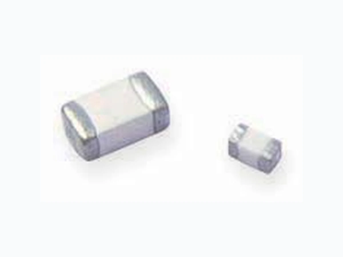
Surface-mount Fuses– Pulse Tolerant Chip Fuses Pulse Tolerant chip fuses has high inrush current withstand capability and provide overcurrent protection on DC power systems. Silver fusing element, monolithic and multilayer design provides strong arc suppression characteristics. These RoHS-compliant surface-mount devices facilitate the development of more reliable, high performance consumer electronics such as laptops, multimedia devices, cell phones, and other portable electronics.
- High inrush current withstanding capability
- Ceramic Monolithic structure
- Silver fusing element and silver termination with nickel and tin plating
- Excellent temperature stability
- Strong arc suppression characteristics
- Lead free materials and RoHS compliant
- Halogen free (refers to: Br/H11349900ppm, Cl/H11349900ppm, Br+Cl/H113491500ppm)
- Monolithic, multilayer design
- High-temperature performance
- -55°C to +125°C operating temperature range
- L a p t o p s
- Digital cameras
- Cell phones Benefits Features
Applications
- Printers
- DVD players
- Portable electronics
- G a m es y s t e m s
- LCD monitors
- Scanners Surface-mount Fuses Pulse Tolerant Chip Fuses NEW NENENENENENENENENENENENEWWWWWWWWWWWWNEW s has hi gh inrush current ovide overcurrent protection er fusing element, monolithic vides strong arc suppressio n ace-mount devices facilitateeeee reliable, high performan cceccccc cha sl a ptops, mul tiiitittt memmmmm dddidddd a ther portable electroooooonicsssss. tanddddingggggg ccacccc papabilityyyyyyy ure silveeeeeert e rmmimmmm nannaanann tion with bility
- Lead free materials and RoHS
- Halogen free (refers to: Br /H11349 900ppm, Cl /H11349 900
- Monolithic, multilayer design
- H igh-temperature performanc
Features
p
78 RoHS Compliant, ELV Compliant HF Halogen Free
% of rated current Clear time at 25°C 100% 4 hours (min.) 200% 1 seconds (min.) 60 seconds (max.) 1000% 0.0002 second (min.) 0.02 seconds (max.) 0603SFP100F/32-2 1.0 0.210 0.080 32 50 0603SFP150F/32-2 1.5 0.101 0.11 32 50 0603SFP200F/32-2 2.0 0.057 0.24 32 50 0603SFP250F/32-2 2.5 0.042 0.56 32 50 0603SFP300F/32-2 3.0 0.030 0.72 32 50 0603SFP350F/32-2 3.5 0.022 1.10 32 50 0603SFP400F/32-2 4.0 0.018 2.08 32 50 0603SFP450F/32-2 4.5 0.014 2.63 32 50 0603SFP500F/32-2 5.0 0.013 3.25 32 50 1206SFP100F/63-2 1.0 0.340 0.11 63 50 1206SFP150F/63-2 1.5 0.150 0.33 63 50 1206SFP200F/63-2 2.0 0.090 0.80 63 50 1206SFP250F/32-2 2.5 0.070 1.19 32 50 1206SFP300F/32-2 3.0 0.035 1.35 32 50 1206SFP350F/32-2 3.5 0.029 1.84 32 50 1206SFP400F/32-2 4.0 0.023 2.74 32 50 1206SFP450F/32-2 4.5 0.021 3.20 32 50 1206SFP500F/32-2 5.0 0.017 5.50 32 50 * Measured at /H1134910% of rated current and 25°C ambient temperature. † Melting I2t at 0.001 sec clear time. 0603 (1608 mm) Pulse Tolerant Chip Fuses 1206 (3216 mm) Pulse Tolerant Chip Fuses A B C D Shape and Dimensions mm (Inch) Table FP1Clear Time Characteristics for Pulse Tolerant Chip Fuses Table FP2Typical Electrical Characteristics and Dimensions for Pulse Tolerant Chip Fuses Part Number Rated Current (A) Nominal Cold DCR (Ω)* V oltage (VDC) Current (A) Nominal I2t (A2sec)† T ypical
Electrical Characteristics
Max. Interrupt Ratings Part Number Rated Current (A) Nominal Cold DCR (Ω)* V oltage (VDC) Current (A) Nominal I2t (A2sec)† T ypical Max. Interrupt Ratings ABCD Min Max Min Max Min Max Min Max ABCD Min Max Min Max Min Max Min Max A B C D Shape and Dimensions mm (Inch) Clear time at 25°C 4 hours (min.) 1 seconds (min.) 60 seconds (maxmaxaamam .) 0.0002 second (min.) 0.02 secondsds (sdss maxaax.) 06006600003SF3S3SFS3 P100F/332-21 .22 0 0.210 0603SFSSFP150F/F///332-3 2 1.5 0.101 0603SFSSFP200020202 0F/32-2 2.0 0.057 0603SSSFSS3S P250F/32-2 2.5 0.042 0660600600 3SFP300F/32-2 3.0 0.030 0603SFP350F/32-2 3.5 0.022 0603SFP400F/32-2 4.0 0.018 0603SFP450F/32-2 4.5 0.014 0603SFP500F/32-2 5.0 0.013 e Tolerant ChipF usesssss e Tolereeeee anttCttttt hihhhhh p Fuses D e Characteristics for Pulse Tolerant Chip Fuses ectrical CharacteristicsanndDddddd iimeensionnsf orr PPulssseTTTTToleran PPartN uumbemb r Rattteddddd Currenrrrerr t (A) Nomin ColdD C Ω TTTy pica EllectricaallC hll ara Typica Electrical Chara B C D Maaxaaaa Miniinn Maxxxx MinMinMinnMM Max A B CC D
Surface-mount Fuses– Pulse Tolerant Chip Fuses RoHS Compliant, ELV Compliant HF Halogen Free Clear Time (s) 10 0 0.1 0.01 0.001 0.0001 10 10 01 Current (A) 0603SFP Average Time Current Curves A 4.5A5.0 A Figure FP1 I2t( A2s) 10,000 1 000 10 0 0.1 0.01 0.010.001 100.1 1 10 00.0001 Time (s) 0603SFP I2T vs. t Curves 1.0A 1.5A 2.0A 2.5A 3.0A 3.5A 4.0A 4.5A5.0A Figure FP2 Note: Curves are nominal Figure FP1-FP4 Family Performance Curves for Pulse Tolerant Chip Fuses 06006060060060060003SF3 PPPIPPP T vs. t Curves 100 CCurrrrC rrrreent (((A)AA))A)AA
80 RoHS Compliant, ELV Compliant HF Halogen Free
Clear Time (s) 10,000 10 0 0.01 0.001 10 10 01 Current (A) 1206SFP Average Time Current Curves A Figure FP3 I2t( A2s) 1 0,000 10 0 0.01 0.01 11 0 0 1 0,0000.0001 Time (s) 1206SFP I2T vs. t Curves 1.0A 1.5A 2.0A 2.5A 3.0A 3.5A 4.0A 4.5A5.0A Figure FP4 Note: Curves are nominal /barb4rightPlease go to page 97 for more information for Pulse T olerant Chip Fuses. Figure FP1-FP4 Family Performance Curves for Pulse Tolerant Chip Fuses Cont’d 1206SFP I T vs. t Curves Current ((A)A)))A)) 1206SFP Average Time Current Curves A .5A A 2.5A 3.0A 3.5 A 4.0 A A A
Surface-mount Fuses– 0603 Very Fast-Acting Chip Fuses Very Fast-acting chip fuses help provide overcurrent protection on systems using DC power sources up to 32V DC. The fuse’s monolithic, multilayer design provides the highest hold current in the smallest footprint, reduces diffusion-related aging, improves product reliability and resilience, and enhances high-temperature performance in a wide range of circuit designs. These RoHS-compliant surface-mount devices offer strong arc suppression characteristics and facilitate the development of more reliable, high performance consumer electronics such as laptops, multimedia devices, cell phones, and other portable electronics.
- Very fast acting at 200% and 300% overloads
- Excellent inrush current withstanding capability at high overloads
- Thin body for space limiting applications
- Glass ceramic monolithic structure
- Silver fusing element and silver termination with nickel and tin plating
- RoHS compliant and lead-free materials
- Symmetrical design with marking on both sides (optional)
- Lead free materials and RoHS compliant
- Halogen free (refers to: Br/H11349900ppm, Cl/H11349900ppm, Br+Cl/H113491500ppm)
- Monolithic, multilayer design
- High-temperature performance
- -55°C to +125°C operating temperature range
- L a p t o p s
- Digital cameras
- Cell phones Benefits Features
- Printers
- DVD players
- Portable electronics
- G a m es y s t e m s
- LCD monitors
- Scanners Surface-mount Fuses
0603 Very Fast-Acting Chip Fuses
NENENENENENENENENENENENEWWWWWWWWWWWWNEW ng DC power sources up to c, multilayer design provides in the smallest footprint , aging, improves produc t d enhances high-temperature ge of circuit designs. urface-mount devices offe r racteristics and facilitate the eliable, high per formanceeeeeee ch as laptops, mu ltimediiiiiia ther portablee lectroninniinin cscccccccc . and 300000000000%%%%% ovooo erloaddaaadadddddsssssss withsssstanddingcggg apappababbbiliiiii ityayyyyyyyyyyy ttttttttttt ngaaaaaapppppliccacc ttiittttt onnnssssssss struuuuctuuuuuuuuuureeeeeeeee silveeeeertttttttteereeeeee mmimmmmmmmmm nnatiooonoooooooo with -freeeeeeeee mattetetettttttt rials markiniiniinnngggogggggg n both sides
- LLLLLLLLLLeead free materials and RoHS
- Halogen free (refers to: Br /H11349 900ppm, Cl /H11349 900
- Monolithic, multilayer design
- H igh-temperature performanc
- -55°C to +125°C operating tem FFeattuuruuuuuuu es
82 RoHS Compliant, ELV Compliant HF Halogen Free
% of rated current Clear time at 25°C 100% 4 hours (min.) 200% 0.01 second (min.) 5 seconds (max.) 300% 0.001 second (min.) 0.2 seconds (max.) 0603SFV050F/32-2 0.5 0.860 0.0093 32 50 0603SFV075F/32-2 0.8 0.450 0.0191 32 50 0603SFV100F/32-2 1.0 0.280 0.0360 32 50 0603SFV125F/32-2 1.3 0.205 0.0630 32 35 0603SFV150F/32-2 1.5 0.143 0.0950 32 35 0603SFV175F/32-2 1.8 0.095 0.1400 32 35 0603SFV200F/32-2 2.0 0.073 0.2100 32 35 0603SFV250F/32-2 2.5 0.046 0.3000 32 35 0603SFV300F/32-2 3.0 0.039 0.4600 32 35 0603SFV350F/32-2 3.5 0.028 0.7300 32 35 0603SFV400F/32-2 4.0 0.023 1.1500 32 35 0603SFV450F/32-2 4.5 0.019 1.6800 32 35 0603SFV500F/32-2 5.0 0.015 2.6200 32 35 * Measured at 10% of rated current and 25°C Part Number 0603 (1608 mm) Very Fast-Acting Chip Fuses A B C D Shape and Dimensions mm (Inch) Table FV1Clear Time Characteristics for Very Fast-Acting Chip Fuses Table FV2Typical Electrical Characteristics and Dimensions for Very Fast-Acting Chip Fuses Rated Current (A) Nominal Cold DCR (Ω)* V oltage (VDC) Current (A) Nominal I2t (A2sec) T ypical Electrical Characteristics Max. Interrupt Ratings /barb4rightPlease go to page 97 for more information for V ery Fast-Acting Chip Fuses. 11 0 0 10 Clear Time (s) 10 0 0.1 0.01 0.001 0.0001 Current (A) 0603SFV Average Time Current Curves A 3.50A4.00A4.5 5.00A 0603SFV I²t vs. t Curves I²t (A²s) Time (s) 1 000 10 0 0.1 0.01 0.001 0.0001 0.0001 0.001 0.10.01 1 10 5.00A 4.50A 4.00A 3.50A 3.00A 2.50A 2.00A 1.75A 0.75A 0.05A 1.25A 1.50A 1.00A Figure FV2Figure FV1 Note: Curves are nominal Figure FV1-FV2 Family Performance Curves for Very Fast-Acting Chip Fuses ABCD Min Max Min Max Min Max Min Max 0603SFV I²t 1000 erageeTeeeeee ime CurCuCuCCCCCCCurreerenererererr t Curves 3.00 A 3.50A 4.000000000000000000 AAAAAAAA 444.444444 A 4h ours (min.) 0.01 second( min.) 5 seconds (max.) 0.001 second (min.) 0.2 seconds (max.) 0603S3S3SF3S3S3S3S3S3S V05V0550F/322-20 0.0 50 0.0 86660 0.0 0603SSSFSSSSSSSS V07V0775F/322-20 00.80 0.0 450550000 0.0 0603SSSFSSSSSSSS V10V1000F/322-21 1.00 0.0 280 0.0 06006006000600060060060060003SSFSSSS V12V1225F/322-2 1.30 0.0 205 0.0 006000000003SSFS V15V1550F/322-2 1.50 0.0 143 0.0 06000003SFV17V1775F/322-21 11.1111 80 0.0 095095995090909 0. 0600003SFV20V2000F/322-22 2.00 . 073 0.2 0600003SFSSS V25V2550F/F///3232-33333333 22 .50 . 046 0.3 060000003SSFSSS V30V30000000000F/0000 32-32 23 .0 0.039 0.4 060000003SSFSS VV350F/32-32 2 3.5 0.028 0.7 60060606060606060603SSSFSSS VV400F/32-32--224 .22222 0 0.023 1. 06000 3SSFSSSSSSS VV450F///F/F/F/F0FF0F 3332-33 2 4.5 0.019 1.6 06033S3SF333333 V50V50050505V55V 0F/32-2 5.0 0.015 2.6 *M eeaeeeee sured at 10% of rated current and 25°C ParaaParraaParrPararParartN utN utttttt mbbber y Fast-Acting Chip Fuses A B C D ectrical Characteristics and Dimensionsf orrorororoooo Veryryy FaaFaaaFaFaFaFF st-Ac RRRatRRRR ed Currenttt (A)(AA( NNominaallllll CoooldD CDCCDCCCDDDDDD R ΩΩ No Ty ppypppyyy icacacaacacacaccc lE lllectrrrical Chaaaracter Figure FV2 ily Peerffororoorrmamam nncnnnnnnnn eCCeCCeCCCeCCeCCeCCurvvevvvvvvv s for Very Fast-Acting Chip Fuses C D axM i n Maxaxaxaxxaxaxaxaa MinMiMinMMinnMMinnMinM n MaxMaxMaxMMaxM xM xxM xxM xx 48 0.2 10 .111 5551 0 .656555666655 0.95
Surface-mount Fuses– Fast-Acting Chip Fuses Fast-acting chip fuses help provide overcurrent protection on systems using DC power sources up to 63V DC.T h e fuse’s monolithic, multilayer design provides the highest hold current in the smallest footprint, reduces diffusion- related aging, improves product reliability and resilience, and enhances high-temperature performance in a wide range of circuit designs. These RoHS-compliant surface-mount devices offer strong arc suppression characteristics and facilitate the development of more reliable, high performance consumer electronics such as laptops, multimedia devices, cell phones, and other portable electronics.
- Small size with high-current ratings
- Excellent temperature stability
- High reliability and resilience
- Strong arc suppression characteristics
- Lead free materials and RoHS compliant
- Halogen free (refers to: Br/H11349900ppm, Cl/H11349900ppm, Br+Cl/H113491500ppm)
- Monolithic, multilayer design
- High-temperature performance
- -55°C to +125°C operating temperature range
- L a p t o p s
- Digital cameras
- Cell phones Benefits Features
- Printers
- DVD players
- Portable electronics
- G a m es y s t e m s
- LCD monitors
- Scanners Surface-mount Fuses Fast-Acting Chip Fuses rovide overcurrent protection ers o u r c e su pt o6 3 V DC . The r design provides the highest footprint, reduces diffusion- duct reliability and resilienceeeecece, ature performance in awaaaaa iddddddde urface-mounttntntnn devivvivviiviviiceececeesososososs os os offfff eree racteriststttics and faaaaacciccc liitttatattt tte thttt eee eliabllleee,eee hhhihhhhh gggh peeeeerrrfr ormamamamamannncn ee ch asslssss appppppptooops,m,mmmmmm,mmulu timeeeeeeeeeediaaaa ther portablbbblbbbb eeeeellelll cctccc rororroroonicsssss.... nt raaaaaaatingggggsssss bility
- Lead free materials and RoHS
- Halogen free (refers to: Br /H11349 900ppm Cl /H11349 900
84 RoHS Compliant, ELV Compliant HF Halogen Free
% of rated current Clear time at 25°C 100% 4 hours min. 250% 5 seconds max. 400% 0.05 seconds max. 0402SFF050F/24 0.50 0.380 0.0043 24 35 0402SFF075F/24 0.75 0.210 0.0076 24 35 0402SFF100F/24 1.00 0.120 0.0170 24 35 0402SFF150F/24 1.50 0.056 0.0490 24 35 0402SFF200F/24 2.00 0.035 0.0700 24 35 0402SFF300F/24 3.00 0.021 0.1250 24 35 0402SFF400F/24 4.00 0.014 0.2250 24 35 Part Number 0603SFF050F/32 0.50 0.485 0.0029 32 50 0603SFF075F/32 0.75 0.254 0.0064 32 50 0603SFF100F/32 1.00 0.131 0.0160 32 50 0603SFF150F/32 1.50 0.059 0.0300 32 35 0603SFF200F/32 2.00 0.044 0.0600 32 35 0603SFF250F/32 2.50 0.032 0.1150 32 35 0603SFF300F/32 3.00 0.025 0.1900 32 35 0603SFF350F/32 3.50 0.024 0.2950 32 35 0603SFF400F/32 4.00 0.018 0.4000 32 35 0603SFF500F/32 5.00 0.013 0.7000 32 35 0603SFF600F/24 6.00 0.010 1.1250 24 35 1206SFF050F/63 0.50 0.730 0.0021 63 50 1206SFF075F/63 0.75 0.513 0.0052 63 50 1206SFF100F/63 1.00 0.220 0.0120 63 50 1206SFF150F/63 1.50 0.120 0.0250 63 50 1206SFF175F/63 1.75 0.100 0.0450 63 50 1206SFF200F/63 2.00 0.050 0.0700 63 50 1206SFF250F/32 2.50 0.035 0.1400 32 50 1206SFF300F/32 3.00 0.031 0.2200 32 50 1206SFF400F/32 4.00 0.022 0.3800 32 45 1206SFF500F/32 5.00 0.015 0.6000 32 45 1206SFF600F/32 6.00 0.013 1.0000 32 50 1206SFF700F/32 7.00 0.011 1.7500 32 50 1206SFF800F/32 8.00 0.008 2.5000 32 50 1206SFF600F/24 6.00 0.013 1.0000 24 45 1206SFF700F/24 7.00 0.011 1.7500 24 45 1206SFF800F/24 8.00 0.008 2.5000 24 45 * Measured at /H1134910% of rated current and 25°C ambient temperature. † Melting I2t at 0.001 sec clear time. 0402 (1005mm) Fast-Acting Chip Fuses 0603 (1608mm) Fast-Acting Chip Fuses 1206 (3216mm) Fast-Acting Chip Fuses 0.063 (1 .60) 0.039±0.004 (1 .00±0.1 0) 0.020±0.004 (0.51±0.1 0) 0.0 1 0±0.004 (0.25±0.1 0) 0.020±0.004 (0.51±0.1 0) Shape and Dimensions Inch (mm) Recommended Pad Layout Inch (mm) 0.028 (0.70) 0.024 (0.60) 0.0 16 (0.40) Shape and Dimensions Inch (mm) Recommended Pad Layout Inch (mm) 0.031±0.006 (0.80±0.15) 0.031±0.006 (0.80±0.15) 0.0 14±0.006 (0.36±0.15) 0.063±0.006 (1 .60±0.15) 0.1 1 0 (2.80) 0.039 (1 .00) 0.043 (1 .09) 0.024 (0.60) Shape and Dimensions Inch (mm) Recommended Pad Layout Inch (mm) 0.063±0.008 (3.20±0.20) 0.043±0.008 (1 .1 0±0.20) 0.020±0.0 1 0 (0.51±0.25) 0.173 (4.40) 0.071 (1 .80) 0.057 (1 .45) 0.059 (1 .50) Table FF1Clear Time Characteristics for Fast-Acting Chip Fuses Table FF2Typical Electrical Characteristics, Dimensions and Recommended Pad Layout for Fast-Acting Chip Fuses Rated Current (A) Nominal Cold DCR (Ω)* V oltage (VDC) Current (A) Nominal I2t (A2sec)† T ypical Electrical Characteristics Max. Interrupt Ratings Part Number Rated Current (A) Nominal Cold DCR (Ω)* V oltage (VDC) Current (A) Nominal I2t (A2sec)† T ypical Electrical Characteristics Max. Interrupt Ratings Part Number Rated Current (A) Nominal Cold DCR (Ω)* V oltage (VDC) Current (A) Nominal I2t (A2sec)† T ypical Electrical Characteristics Max. Interrupt Ratings 0400002SFFS FF050F/24 0440 00.50 0.380 0 .0 004004004000 00400 2SSFSSS FF075F/24440 .75 0.210 0 .0 040004404 2SSSFSSS FF100F///F/2224 122 .00 0.120 0 .0 0402SSFSSSS F15F15551 00F/24 1.50 0.056 0 .0 040222SF222 F200F/24 2.00 0.035 0 .0 04040000404 2SFF300F/24 3.00 0.021 0 .1 0402SFF400F/24 4.00 0.014 0 .2 ParrrrrtN utN utNtN utN ut mbembebeeber 0603SFF050F/32 0.50 0.485 0 .0 S -Acting ChipFFFFFuuseeseeee ActtttttingCgCgCgCg Cg CCg hhhihhhhh pppF useeeseee 0.0633333 1.6 00)000 0.039±0. 004 0.020±0.0±000000 004 (0.51±0.1±00 10) ±0. 004 ±0. 10 ) 0.028888 (00.700))0)0)0)0) 0.0 16 (0.4000)0 Clear time at 25°C 4 hours min. 5s e c onds max. 0.05 seconds max. 0.031±0. 006 (0 80±0 15) 0.063±0.. 006 1.6 0±000.000 15) e Characteristics for Fast-Acting Chip Fuuuuusssses s ectrical Characterissssstittitit cscccc , Dimeneneeeee siionssa nd Reeecooommmmmeeene ddded g Chip Fuses Ratted Currrenttt (AA) Nominal Cold DCR Ω No Ty pTTy pTT icaallE lleectricriicricci al Character Part Number Rated Current (A) Nominal Cold DCR Ω No Typical Electrical Character
Surface-mount Fuses– Fast-Acting Chip Fuses RoHS Compliant, ELV Compliant HF Halogen Free 0.1 1 0 11 0 0 Clear -Time (s) 0.1 0.0 1 0.00 1 Current (A) 0402SFF Average Time Current Curves 0.00 1 0.0 1 0.1 1 1 0 1 000 10 0 0.1 0.0 1 0.00 1 I²t (A²s) Time (s) 0402SFF I²t vs. t Curves 0.5A 0.75A 1.0A 1.5A 2.0A 3.0A 4.0A Figure FF2Figure FF1 0.1 0.0 1 0.00 1 10 . 1 10 10 0 Current (A) Clear -Time (s) 0603SFF Average Time Current Curves 0.00 1 0.0 1 0.1 1 1 0 1 0000 1 000 10 0 0.1 0.0 1 0.00 1 I²t (A²s) Time (s) 0603SFF I²t vs. t Curves 0.5A 0.75A 1.0A 1.5A 2.0A 2.5A 3.0A 3.5A 4.0A 5.0A 6.0A Figure FF4Figure FF3 Note: Curves are nominal Note: Curves are nominal Figure FF1-FF6 Family Performance Curves for Fast-Acting Chip Fuses 1 0000 1000 0603SFF I²t vs . 1000000 urrenttt(t AA)A)A e Time Current Curves A .75A A A 0.00 1 0.01 0.1 1000 10 00 100 0.11 0.0 1001 0000.000 1 I²t (I²t (It( A²s)A²s)As ) Time (s) 040004000 2SFFI ²²tv s . Figure FF2 e Timmemm CurCuCuCuCuCu reeeneneee ttC urveeeees A A .5AAA 22.2222 000 A 2.5A 3.0A A 3.5 A 4.000 AAAAAA 555.55 A 60 A6.0A.0A Figure FF4 Note: Curves are nominal
86 RoHS Compliant, ELV Compliant HF Halogen Free
0.1 1 0 11 0 0 Clear -Time (s) 0.1 0.0 1 0.00 1 Current (A) 1206SFF Average Time Current Curves I²t (A²s) 1 0000 1 000 10 0 0.1 0.0 1 0.00 1 Time (s) 1206SFF I²t vs. t Curves 0.00 1 0.0 1 0.1 1 1 0 0.5A 0.75A 1.0A 1.5A 1.75A 2.0A 2.5A 3.0A 4.0A 5.0A6.0A 7. 0 A 8.0A Figure FF6Figure FF5 Note: Curves are nominal /barb4rightPlease go to page 97 for more information for Fast-Acting Chip Fuses. Figure FF1-FF6 Family Performance Curves for Fast-Acting Chip Fuses Cont’d 100 Cuuurrennt (enn AAAA)AA erage Time Current Curves 75A A .5A 1.75 A A 2.5A 3.0A 4.0 A A 6.0A 7. 0 A I²t (A²s) 1 0000 100000 100 000.10 0.01 0.001 Tim 120220002 6SSSFFI ²t 0.00 1 0.01 Figure FF66 Note: Curves are nominal moreeieeee nforrmarrrr tion for Fast-Acting Chip Fuses. ily Performance Curves for Fast-Acting Chip Fussssssses
High-Current Rated Chip Fuses The monolithic multilayer design of the TE Circuit Protection high-current-rated chip fuses helps to provide some of the highest current ratings available in the 1206 size and enhances high-temperature performance in a wide range of circuit protection designs. The devices’ small size, high reliability and strong arc suppression characteristics make them suitable for overcurrent protection of power supplies, servers, communications equipment, voltage regulator modules, and other high-current, small size applications.
- Glass ceramic monolithic structure provides stability in application cycling
- High-current rating in a small package allows more efficient use in system space
- Strong arc suppression in overcurrent conditions
- Lead free materials and RoHS compliant
- Halogen free (refers to: Br/H11349900ppm, Cl/H11349900ppm, Br+Cl/H113491500ppm)
- Monolithic multilayer design
- High-temperature performance
- -55°C to +125°C operating temperature range
- Communications equipment
- Voltage regulator modules
- Power supplies
- Servers Benefits Features
High-Current-Rated Chip Fuses ent nhances high-temperature ange o f circuit protection all size, high reliability an d characteristics make them otection of power supplies, quipment, voltage regulator rrent, small size applications. struccccctuurerrrr prpprrpp ovvviddiddideeseee ststsstttabilittttty mall paaacaaaa kkakk gegge allowswwswwswsss momomoommom reeee ace oveeerccurrrrer ntntntnn coonndnnnnn itiiittttttttions
- L••• eadffreereeer e materials and RoHS
- Hallooogooo en free (r(rr( efers to: Br /H11349 900ppm, Cl /H11349 900
- Monolithic multilayer design
- High-temperature performanc
- -55°C to +125°C operating tem FFeaturres
88 RoHS Compliant, ELV Compliant HF Halogen Free
% of rated current Clear time at 25°C 100% 4 hours (min.) 250% 5 seconds (max.) 1206SFH Series 1206SFH100F/24 10 0.010 9 24 100 1206SFH120F/24 12 0.008 14 24 100 1206SFH150F/24 15 0.005 26 24 100 1206SFH200F/24 20 0.003 56 24 100 * Measured at /H1134910% of rated current and 25°C ambient temperature. † Melting I2t at 0.001 sec clear time. Part Number Rated Current (A) Nominal Cold DCR (Ω)* Voltage (VDC) Current (A) 1206 (3216mm) High-Current-Rated Chip Fuses Shape and Dimensions Inch (mm) Recommended Pad Layout Inch (mm) 0.063±0.008 (3.20±0.20) 0.038±0.008 (0.97±0.20) 0.020±0.010 (0.51±0.25) 0.173 (4.40) 0.071 (1 .80) 0.057 (1 .45) 0.059 (1 .50) Nominal I2t (A2sec)† T ypical Electrical Characteristics Max. Interrupt Ratings 10 10 0 0 10 0 Clear Time (s) 0.1 0.01 0.001 Current (A) 1206SFH Average Time Current Curves 10A12A15 A 20A 0.00 1 0.0 1 0.1 1 1 0 1 0000 1 000 10 0 I²t (A²s) Time (s) 1206SFH I²t vs. t Curves 20A 15A 12 A 10A Figure FH2Figure FH1 Note: Curves are nominal Table FH1Clear Time Characteristics for High-Current-Rated Chip Fuses Table FH2Typical Electrical Characteristics, Dimensions and Recommended Pad Layout for High-Current-Rated Chip Fuses Figure FH1-FH2 Family Performance Curves for High-Current-Rated Chip Fuses /barb4rightPlease go to page 97 for more information for High-Current-Rated Chip Fuses. 120000066SFH100F/00F 24 10 0.010 12000002 66SFH120F/00F 24424 1242 2 0.008 1222022 66SFH1555000F/00 24 15 0.005 12202222 6SF6SFFFHHH20H 0F/24 20 0.003 ***M e a* sured at /H11349 10% of rated current and 25°C ambien t at 0.001 sec clear time. Parrrrrt Nuumbembembemmm rr RRateeed Currenenenntttt (A)) Nominal Cold DCR Ω Current-Rated Chipp Fuseeeeesssss 0.126±0. 0008 (3.233.2220±0.200) 0.0333338±000.000 008 (0..9. 7±0.0 20)22 0.020±0.±±± 011011 (0.51±±0.± 2255) 0.173 (4.40) 0.071 1.8 0.059 1.5 rt imea t 25°C 4 hours (min.) econds (max.) N Ty ppicalEEElEl ectrical Chahahaaarracteristics e Characteristics for High-Current-Rated ChipFFFFpFpp uuses ectrical Characteristics,DDDDDDDDimmmmmmmennsiionsasaaandddndndn Reeecooommmmmmended ent-Rated Chip Fuses ily PePePPeeeerffffffoormance Curvesfor High-Current-Rated Chip Fus
Surface-mount Fuses– Slow-Blow Chip Fuses Available in industry standard 1206 and 0603 chip sizes, TE Circuit Protection’s slow-blow chip fuses help provide overcurrent protection on systems that experience large and frequent current surges as part of their normal operation. The slow-blow chip fuse’s monolithic, multilayer design helps provide some of the highest current ratings available in the 1206 and 0603 footprints and enhances high-temperature performance in a wide range of circuit protection designs. The devices’ small size, high reliability and strong arc suppression characteristics make them suitable for overcurrent protection of power supplies, capacitor filter banks, LCD (Liquid Crystal Display) backlight inverters, electric motors and portable electronics.
- Time-delayed design prevents nuisance openings in pulsed and high inrush current applications
- Small size with high-current ratings
- Strong arc suppression characteristics
- Lead free materials and RoHS compliant
- Halogen free (refers to: Br/H11349900ppm, Cl/H11349900ppm, Br+Cl/H113491500ppm)
- Monolithic multilayer design
- High-temperature performance
- -55°C to +125°C operating temperature range
- Small motors systems
- Portable electronics
- Input power ports Benefits Features
- Power over Ethernet (POE)
- Test equipment
- POL converter protection
- Computer drives
- Displays
- Printers Surface-mount Fuses Slow-Blow Chip Fuses rd 1206 and 0603 chip sizes, low-blow chi p fuses hel p tection on s ystems tha t ent current surges as part of monolithic, multilayer design he highest current rating s 603 footprints and enhancessssss nce in a wide range of circuuuuuit devices’ sma ll sizeeeeee,h,,, igggggggh suppression c haracccccterisstsstssticii sssss rcurrent proteccccctittititiononoono of pooooowwwewwww rrrrrr banks, LC DDD(DD Liquuuuuidddddddd CrCrCrCCrCrCCC ysysyyssysy taaaaal ters,e eelelleeeectrrricm otooooooo ororroorrsa asa anddddd venttsnnuisssas ncnnnn eooooooopepeenninnnnnn ngs currrerr nnt aapaappppplpp icccaataa ioonnssnss nt rrraratiiiiiiingggggggs haractcccc ereerrerrristiiiiiiiccss
- Lead free materials and RoHS
- Halogen free (refers to: Br /H11349 900ppm, Cl /H11349 900
- Monolithic multilayer design
- H igh-temperature performanc
- -55°C to +125°C operating tem
90 RoHS Compliant, ELV Compliant HF Halogen Free
% of rated current Clear time at 25°C 100% 4 hours (min.) 200% 1 second (min.) 120 seconds (max.) 300% 0.1 second (min.) 3 seconds (max.) % of rated current Clear time at 25°C 100% 4 hours (min.) 200% 1 second (min.) 120 seconds (max.) 300% 0.1 second (min.) 3 seconds (max.) 0603SFS Series 1206SFS Series 1206SFS100F/63 1.0 0.360 0.11 63 50 1206SFS125F/63 1.25 0.200 0.22 63 50 1206SFS150F/63 1.5 0.150 0.23 63 50 1206SFS200F/63 2.0 0.088 0.63 63 50 1206SFS250F/32 2.5 0.065 0.90 32 50 1206SFS300F/32 3.0 0.034 1.20 32 50 1206SFS350F/32 3.5 0.028 1.60 32 50 1206SFS400F/32 4.0 0.024 2.20 32 50 1206SFS450F/32 4.5 0.020 3.60 32 50 1206SFS500F/32 5.0 0.016 5.30 32 50 1206SFS550F/24 5.5 0.014 6.40 24 50 1206SFS600F/24 6.0 0.011 8.50 24 60 1206SFS700F/24 7.0 0.010 10.00 24 60 1206SFS800F/24 8.0 0.009 16.90 24 60 * Measured at /H1134910% of rated current and 25°C ambient temperature. † Melting I2t at 0.001 sec clear time. Part Number Rated Current (A) Nominal Cold DCR (Ω)* Voltage (VDC) Current (A) 1206 (3216mm) Slow-Blow Chip Fuses 0603 (1608mm) Slow-Blow Chip Fuses Shape and Dimensions Inch (mm) Recommended Pad Layout Inch (mm) 0.063±0.008 (3.20±0.20) 0.038±0.008 (0.97±0.20) 0.020±0.0 1 0 (0.51±0.25) 0.173 (4.40) 0.071 (1 .80) 0.057 (1 .45) 0.059 (1 .50) Nominal I2t (A2sec)† 0603SFS100F/32 1.0 0.200 0.093 32 50 0603SFS150F/32 1.5 0.100 0.18 32 50 0603SFS200F/32 2.0 0.052 0.32 32 50 0603SFS250F/32 2.5 0.041 0.63 32 50 0603SFS300F/32 3.0 0.031 0.87 32 50 0603SFS350F/32 3.5 0.021 1.20 32 50 0603SFS400F/32 4.0 0.017 2.30 32 50 0603SFS450F/32 4.5 0.015 2.70 32 50 0603SFS500F/32 5.0 0.013 3.20 32 50 Part Number Rated Current (A) Nominal Cold DCR (Ω)* Voltage (VDC) Current (A) Nominal I2t (A2sec)† Shape and Dimensions Inch (mm) Recommended Pad Layout Inch (mm) 0.031±0.006 (0.80±0.15) 0.031±0.006 (0.80±0.15) 0.0 14±0.006 (0.36±0.15) 0.063±0.006 (1 .60±0.15) 0.1 1 0 (2.80) 0.039 (1 .00) 0.043 (1 .09) 0.024 (0.60) T ypical Electrical Characteristics Max. Interrupt Ratings T ypical Electrical Characteristics Max. Interrupt Ratings Table FS1Clear Time Characteristics for Slow-Blow Chip Fuses Table FS2Typical Electrical Characteristics, Dimensions and Recommended Pad Layout for Slow-Blow Chip Fuses Blow Chip Fuses -Blow Chip Fusesssssss 06603SFFFSFSFSS SSS100F/32 1.0 0.20 0 06060060600606066 3SFS150F/32 1.5 0.10 0 0603SFS200F/32 2.0 0.05 2 0603SFS250F/32 2.5 0.04 1 0603SFS300F/32 3.0 0.03 1 0603SFS350F/32 3.5 0.02 1 0603SFS400F/32 4.0 0.01 7 0603SFS450F/32 4.5 0.01 5 0603SFS500F/32 5.0 0.01 3 Paart Numbemmbebebebbb r Rated Current (A) Nominal Cold DCR Ω 006 0.15) 0.031±0. 0000600000 (0.80±0.15)11111 0.0 144±0.4±0 000006 (0.3366±0.6 15) 0.063±0.3±03±0333 0066 1.6 0±0.00±000000 15) 0.1110 (2.880) 0.030000.. 9 0.00200 4 (0.6666660) ar timea t 25°C 4 hours (min.) 1 second( min.) 120 seconds (max.) 1 second( min.) 3 seconds (max.) 5 second( min.) 0.05 seconds (max.) 1 second (min.) 0.05 seconds (max. ))))) %o fr ated cdcccccdccdd urrent CCleC ar time 100100011 %%% 4h ou 200%%% 111s eco 300%%%%% 0.111 seco 8000%(1(1(1(11 0.0A-1.555A)) 0.001666661 seco 1206SFS Serrrieeieieii s TypicalE lectric Characteristic e Characteristics for Slow-Blow Chip Fuses ectrical Characteriiisisiiiiii ticcsccccccccc ,,D,,D,D,D,, imimiimiiimiimeneneeee siionssa ndddddddddd Reeecooommmenddded w Chip Fuses
Surface-mount Fuses– Slow-Blow Chip Fuses RoHS Compliant, ELV Compliant HF Halogen Free Clear Time (s) 10 0 0.1 0.0 1 0.00 1 10 10 01 Current (A) 0603SFS Average Time Current Curves 1.0A 1.5A 2.0A 2.5 A Figure FS1 I2t( A2s) 1 0,000 1 000 10 0 0.1 0.0 1 0.00 1 0.0 1 100.1 1 10 0 Time (s) 0603SFS I²t vs. t Curves 1.0A 1.5A 2.0A 2.5A 3.0A 3.5A 4.0A 4.5A 5.0A Figure FS2 Note: Curves are nominal Figure FS1-FS4 Family Performance Curves for Slow-Blow Chip Fuses 06000 3SFS I²t vs. t Curves 110 Cuurruu eent (A) 0603SFS Average Time CurrentC urves 1.0A 1.5A A 2.5 A 3.0 A 3.5 A 4.0A A
92 RoHS Compliant, ELV Compliant HF Halogen Free
Clear Time (s) 10 0 0.1 0.0 1 0.00 1 10 10 0 1 0001 Current (A) 1206SFS Average Time Current Curves 1.0A 1.25A1.5A2.0 A Figure FS3 I2t( A2s) 1 00000 1 0000 1 000 10 0 0.1 0.0 1 0.00 1 0.0 1 100.1 1 10 0 Time (s) 1206SFS I²t vs. t Curves 1.0A 1.5A 2.5A 3.0A 3.5A 4.0A 4.5A 5.0A 5.5A 6.0A 7. 0 A 8.0A 2.0A 1.25A Figure FS4 Note: Curves are nominal Figure FS1-FS4 Family Performance Curves for Slow-Blow Chip Fuses Cont’d /barb4rightPlease go to page 97 for more information for Slow-Blow Chip Fuses. 100 Current (A) 1206SFS AverageT ime CurrennntCtC uCCC rvvves A 25A .5A A 2.5A 3.0A 3.5 A 4.0 A A A 5.5A 6.0A 7. 0 A ily Performance Curves for Slow-Blow ChiiiippFpp ussses
Surface-mount Fuses– 2410 Very Fast-Acting Fuses The 2410(6125) is Wire-in Air SMD Fuse which is very suitable for secondary level overcurrent protection applications. These lead-free surface mount devices offer more reliability and have no end cap falling off risk. Straight wire element in air performs consistent fusing and cutting characteristics.
- Very fast acting at 200% overload current level
- Excellent inrush current withstanding capability
- High reliability and resilience
- Strong arc suppression characteristics
- Copper terminal with nickel and tin plated
- Halogen free, RoHS compliant and 100% lead-free
- Copper or copper alloy composite fuse link
- Fiberglass enforced epoxy fuse body
- Wide range of current rating
- -55°C to +125°C operating temperature range (with de-rating)
- Industrial equipment
- LCD/PDP TV
- Backlight inverter Benefits Features
- Power supplier
- Telecom system
- Networking
- G a m es y s t e m s
- White goods
- Automotive Surface-mount Fuses
2410 Very Fast-Acting Fuses
NENENENENENENENENENENENEWWWWWWWWWWWWNEW Air SMD Fuse which is ver y vel overcurrent protection mount devices offer more cap falling off risk. Straighttttttttttt orms consistent fusing annnnnnnnnnd overrlrrrr oaaadccdcdd cdcccccurrrenttttnttnttttnn level withsstatttttt ndinnnnnnnnngcg cgccgccapability nce haracteristics
- Halogen free, RoHS compliant
- Copper or copper alloy compo
- Fiberglass enforced epoxy fus
- Wide range of current rating
0 Very Fast-Acting Fuses
0 Very Fast Acting Fuses
0 V F t A ti F
94 RoHS Compliant, ELV Compliant HF Halogen Free
% of rated current Clear time at 25°C 100% 4 hours (min.) 2410 (6125 mm) Very Fast-Acting Fuse Shape and Dimensions mm (Inch) D A C B Table SFV1Clear Time Characteristics for 2410 Very Fast-Acting Fuses Table SFV2Typical Electrical Characteristics, Dimensions and Recommended Pad Layout for T ypical Electrical Characteristics Max. Interrupt Ratings Marking Code Rated Current (A) Nominal Cold DCR (Ω)* Nominal I2t (A2sec) Voltage Current (A)(VAC)( V DC) 2410SFV0.50FM/125-2 C 0.5 0.2310 0.10 250 125 50A @ 250VAC 50A @ 125VDC 300A @ 32VDC 2410SFV0.63FM/125-2 S 0.6 0.1740 0.16 250 125 2410SFV0.75FM/125-2 D 0.8 0.1480 0.23 250 125 2410SFV1.00FM/125-2 E 1.0 0.0930 0.59 250 125 2410SFV1.25FM/125-2 F 1.3 0.0700 0.96 250 125 2410SFV1.50FM/125-2 G 1.5 0.0620 1.19 125 125 50A @ 125V AC 50A @ 125VDC 300A @ 32VDC 2410SFV2.00FM/125-2 I 2.0 0.0420 2.75 125 125 2410SFV2.50FM/125-2 J 2.5 0.0310 1.21 125 125 2410SFV3.00FM/125-2 K 3.0 0.0249 1.73 125 125 2410SFV3.15FM/125-2 V 3.2 0.0232 2.20 125 125 2410SFV3.50FM/125-2 L 3.5 0.0220 2.50 125 125 2410SFV4.00FM/125-2 M 4.0 0.0172 4.10 125 125 2410SFV5.00FM/125-2 N 5.0 0.0143 5.90 125 125 2410SFV6.30FM/125-2 O 6.3 0.0100 12.50 125 125 2410SFV7.00FM/125-2 P 7.0 0.0094 14.20 125 125 2410SFV8.00FM/125-2 R 8.0 0.0086 20.30 125 125 2410SFV10.0FM/125-2 Q 10.0 0.0066 29.20 125 125 35A @ 125V AC 50A @ 125VDC 300A @ 32VDC 2410SFV12.0FM/065-2 X 12.0 0.0053 49.20 65 65 50A @ 65VAC 50A @ 65VDC 300A @ 32VDC2410SFV15.0FM/065-2 Y 15.0 0.0038 102.50 65 65 2410SFV20.0FM/065-2 Z 20.0 0.0034 126.20 65 65 50A @ 65VAC 50A @ 65VDC 300A @ 32VDC * Measured at/H1134910% of rated current and 25°C ambient temperature. Recommended Pad Layout mm (Inch) 6.86 (0.270) 3.15 (0.124) 1 .96 (0.077) 2.95 (0.1 16) ABCD Min Max Min Max Min Max Min Max F 1.3 0.0700 0.96 250 E 1.0 00.00000 930 0.59 250 D 0.88 0.111111480 0.23 250 S 0.66 00.10 74074007 074074077 0.16 250 C 0.5 000.2000 3103133 0 0.10 250 4 hours (min.) 0.01 second( min.) 5 seconds (max.) 0.01 second (min.) 20 seconds (max.) Fast-Acting Fuse Electrical Characteristics, Dimensions asass nddd Recoooommmmmmmeneneeene ded ry Fast-Acting Fuses Typyyy iicalE lEllllectttttttriccccccal Charrrrraaacta eerieeee sttitt csss Max. Markinnnng Codeeeeee RRRatededded CurCuuCC rent (A) Nommmminiinnainn l ColCCCCCoo dD CDDDDD R Ω Nominaaal I t sssecs ) Voltage AC G 1.5 0.0620 1.19 125 I 222.0 0.0420 2.75 125 J 2.5 0.0310 1.21 125 K 3.0 0.0249 1.73 125 A BCDBCBCBBC Min Max Minnn MMaxMaxMMM Minnnn MMMax Minninnii Maaax
Surface-mount Fuses– 2410 Very Fast-Acting Fuses RoHS Compliant, ELV Compliant HF Halogen Free /barb4rightPlease go to page 97 for more information for 2410 Fast-Acting Fuses. ClearTime (s) 10 0 0.1 0.01 0.001 10 10 0 0 10 010.1 Current (A) 2410SFV AverageTime Current Curves Figure SFV1 I2t( A2s) 1 00,000 10,000 1 000 10 0 0.1 0.01 0.010.001 100.1 1 10 0 Time (s) 2410SFV I2T vs. t Curves 1.00A 0.50A 0.63A 0.75A 1.50A 1.25A 2.00A 2.50A 3.00A 3.15A 3.50A 4.00A 5.00A 7. 0 0 A 8.00A 10.0A 12.0A 15.0A 20.0A 6.30A Figure SFV2 Figure SFV1-SFV2 Family Performance Curves for 2410 Very Fast-Acting Fuses Note: Curves are nominal 2410SFV I T vs. t Curves 100 100 CuCurrCuCuCu ent (A) 2410SFV AverageTime Current Curves 0.63A 0.50A 0.75A 1.0 0A 1.25A 1.50A 2.00 A 2.50A 3.00A 3.15A 3.50A 4.00A 5.00A 6.30A 7. 0 0 A 8.00A 10.0A 12.0 A 15.0 A 20.0 A
Surface-mount Fuses- Specifications for All Fuses RoHS Compliant, ELV Compliant HF Halogen Free Specifications, Packaging Information, Agency Approvals and Part Numbering Systems for All Fuses Operating temperature -55°C to +125°C Mechanical vibration Withstands 5-3000 Hz at 30 Gs when evaluated per Method 204 of MIL-STD-202 Mechanical shock Withstands 1500 Gs, 0.5 millisecond half-sine pulses when evaluated per Method 213 of MIL-STD-202 Thermal shock Withstands 100 cycles from -65°C to +125°C when evaluated per Method 107 of MIL-STD-202 Resistance to soldering heat Withstands 60 seconds at +260°C when evaluated per Method 210 of MIL-STD-202 Solderability Meets 95% minimum coverage requirement when evaluated per Method 208 of MIL-STD-202 Moisture resistance Withstands 10 cycles when evaluated per Method 106 of MIL-STD-202 Salt spray Withstands 48-hour exposure when evaluated per Method 101 of MIL-STD-202 Storage temperature /H1134930°C/ 85% RH Storage humidity Per MIL-STD-202F , Method 106F Construction body material Ceramic (1206/0603/0402); Fiberglass/Epoxy (2410) T ermination material Silver, Nickel, Tin Fuse element Silver(1206/0603/0402); Copper/Copper Alloy (2410) 1206/0603/0402 Series T emperature Effect on Current Rating T emperature Effect on Current Rating % De-rating % De-rating 105 100 110 105 100 Maximum Operating T emperature (˚C) Maximum Operating T emperature (˚C) -55 -35 -15 5 25 45 65 85 105 125 145 -55 -35 -15 5 25 45 65 85 105 125 Insulation resistance after opening 20,000Ω minimum @ rated voltage. Fuse clearing under low voltage conditions may result in lower - post-clearing insulation values. Under normal fault conditions TE Circuit Protection fuses provide sufficient insulation resistance for circuit protection. Current carrying capacity Withstands 100% rated current at +25°C ambient for 4 hours when evaluated per MIL-PRF-23419. Table F1Environmental Specifications for All Fuses Table F2Material Specifications for All Fuses Figure F1 Thermal Derating Current for All Fuses Table F3Electrical Specifications for All Fuses g 20,000000 Ω minimum @ rated voltage. Fuse clearing under low voltage condit 603/0402 Series ffect on Current Rating 24124112442222 0 Se Te mmmpeerattture Efffeect o %D e% De-% De-eDDDDD%%%%% ratiiratiataararr nggnggngnnn 11000 10555 10000 9555 9000 855555 65556555565 eratinngn Teempppeperaaaaaapp turetuutttttt (˚C)˚C˚CC˚C˚C Maximum OperatingT 45 65 555 85 10 51 2 55555 145 -55 -35 -155 25 Ceramic (1206/0603/0402); Fiberglass/Epoxy (2410) Silver, Nickel, Tin Silver(1206/0603/0402); Copper/Copper Alloy (2410))0)))000 e S 0 , et od 06 fications for All Fuses ting Current for All Fuses cificccccccccationnnsnnnnnn fofofofofoff r All Fuses
98 RoHS Compliant, ELV Compliant HF Halogen Free
Recommended conditions for hand soldering: 1. Using hot air rework station that can reflow the solder on both terminations at the same time is strongly recommended, do not directly contact the chip termination with the tip of soldering iron. 2. Preheating: 150°C, 60s (min). Appropriate temperature (max) of soldering iron tip/soldering time (max): 280°C /10s or 350°C / 3s. 0402(1005) 10,000 178mm white plastic 9.0 ± 0.5mm 8.00 ± 0.10mm Paper 5 1 to 10 0603(1608) 4,000 178mm white plastic 9.0 ± 0.5mm 8.00 ± 0.10mm Paper 5 1 to 10 0603SFV(1608) 6,000 178mm white plastic 9.0 ± 0.5mm 8.00 ± 0.10mm Paper 5 1 to 10 1206(3216) 3,000 178mm white plastic 9.0 ± 0.5mm 8.00 ± 0.10mm Plastic 5 1 to 10 2410(6125) 2,000 178mm white plastic 13.4 ± 0.5mm 12.00 ± 0.10mm Plastic 4 1 to 10 Size Reel Quantity (pcs) Reel Diameter Reel Width Carrier T ape Size T ape T ype Reels per Outside Shipment Box Outside Shipment Boxes per Overpack Table F4Packaging Information for All Fuses Figure F2 Recommended Soldering Temperature Profile for All Fuses Profile Feature 1206/0603/0402 2410 Average ramp up rate (TsMAX to Tp) 3°C/second max. 3°C/second max. Preheat
- T emperature min. (Ts MIN) 150°C 150°C
- T emperature max. (TsMAX) 200°C 200°C
- Time (tsMIN to tsMAX) 60-180 seconds 40-100 seconds Time maintained above:
- T emperature (T L) 217°C 200°C
- Time (tL) 60-150 seconds 30-90 seconds Peak/Classification temperature (Tp) 260°C max. 250°C max. Time within 5°C of actual peak temperature Time (tp) 20-40 seconds 30-40 seconds From 25°C to preheating (150°C) 8 minutes max. 40-100 seconds Ramp down rate 4°C/second max. Natural cooling Critical Zone TL to TpRamp up t 25˚C to Peak Reflow Profile Time Ramp down ts Preheat TsMAX TL Tp tp TsMIN tL T emperature Classification Reflow Profiles 1206/0603/0402 2410 AX too Tp) 3°C/second max. 3°C/second max 150°C 150°C 200°C 200°C 60 180 seconds 40 100 seconds 178mm white plastic 9.0 ± 0.5mm 8.00 ± 0.10 mm P Papeaaa r 178mm white plastic 9.0 ± 0.5mm 8.00 ± 0.10m mP a PaPaper 178mm white plastic 9.0 ± 0.5mm 8.00 ± 0.10m mP ammP amP ammmm perrrrrr 178mm white plastic 13.4 ± 0.5mm 12. 000±0±00000 0.10mmmm PlaPPPlaaP sticcccccc Reel DiameterR eelW idth Carrier TapeS i z e T a pe Ty pppppppypypypy eeee Reels Shi nded Soldering Temperaattatatttaaaaa urePePeeeeeee rooofilee foffoooooooorAr Arrr lll FFuseeess Crittiical Zoneee T L tooT p R amp am uuup t2 55˚5555555 CCt oPCCCCCCCCC eakkkkkkkk R efloefloee wP r owwP r oww filefile Time R amp down tssss P reheeeaataaa TTTs MAX T L Tp tpppptp TTTs MINN t L Tem pera eturere Profffileesee
Surface-mount Fuses- Specifications for All Fuses RoHS Compliant, ELV Compliant HF Halogen Free 11P0 P0 P2 F F W W t Paper Carrier T ape Specifications Plastic Carrier T ape Specifications Table F5Tape and Reel Specifications for All Fuses Figure F3 Component Tape Dimensions for All Fuses Dimension in inches (mm) Mark 0402 (1005) 0603 (1608) 1206 (3216) 0603SFV (1608) 2410 (6125) D1 — — 0.039 max — 0.61 ± 0.004 PPPP P PPaper CCr arrier T ape Specifications TapeDeeDee immmmenenee siiioono sfsss or AAAlAAA l Fuses (1.75 ± 0.10) (1.75 ± 0.10) (1.75 ± 0.10) 0.138 ± 0.002 0.138 ± 0.002 0.138 ± 0.0022 (3.50 ± 0.05) (3.50 ± 0.05) 0.315 ± 0.004 0.315 ± 0.004 (8.00 ± 0.10) (8.00 ± 0.10) 0.157 ± 0.004 0.157 ± 0.004 000.157 ± 0.0004 (4.00 ± 0.10) (4.00 ± 0.10) 0.157 ± 0.004 0.157 ± 0.004 000.157 ±±57 ±555 0.0004 (4.00 ± 0.10) (4.00 ± 0.111000)0 0.079 ± 0.002 0.079 ± 0.00022 0.079 ±779 ±± 0.0002 (2.00 ± 0.05) 0.059 ± 0.004 000.0000 59 ± 0.0000 0444 0.059 ±559 ±± 0.0004 0.0000.0. 39 m39 m39 m3 m3 mmaax ——— (111.1111 00 m0m0m00 ax) ——— 0.00009 ± 0.00.001 ——— 0.0000003939 ±3 0.00004 0.00071 ± 0.00.000 0444 00.039 ±3939 ±±9 0.004 (0.98 ±9899999 0.100)00 (0.98 ± 0.10) 0.071 ±7171 0.0004000 0.11111138 ±888 0.00.000 04 0.071 ± 0.004 (1.80 ± 0.10) 0.0. 37 ±7777 0.003 0.050 ±± 0.0004 0.024± 0.003 (0.60 ± 0.08)
100 RoHS Compliant, ELV Compliant HF Halogen Free
Description Mark 1206/0603/0402 2410 Hub outer diameter B 60 60.2 Reel inside width W 1 9 13.4 Reel outside width W 2 11.4 16 Tape width 8 B Figure F4 Reel Dimensions for All Fuses Agency Approvals for All Fuses UL File # E197536 Part Numbering System for Fast-Acting, Slow-Blow And 0603 Very Fast-Acting Chip Fuses
1206 SF F 400 F / 24 -2
-2 = Tape and Reel Voltage Rating 24 = 24V DC Special Code F = RoHS Compliant FM = RoHS Compliant + Marked Part Rated Current 050 = 0.50 Amps 400 = 4 Amps Fuse Blow T ype F = Fast Acting S = Slow Blow SF = Surface Mount Fuse Size (1206, 0603, 0402) Part Numbering System for High-Current-Rated Chip Fuses
1206 SF H 100 F / 24 -2
-2 = Tape and Reel Voltage Rating 24 = 24V DC Special Code F = RoHS Compliant FM = RoHS Compliant + Marked Part Rated Current 100 = 10 Amps Fuse Blow T ype H = High Current SF = Surface Mount Fuse Size (1206) Dimension (mm) W 11.4 or All Fuses 97536 em for Fast-Acting, Slowwwwwwwwwwww-BlooooooooowAwAAndd 060003 VVVeery Faaasttttstststss -AAA--A- cti 4- 2 Packagggggggginngnnn -2 = TapTTaaTTaaaa eaaanaaaaaa dR eeeel VoVolttagtagtaggtagtt ggt e Rae Reee ting 24 =4 24V2424242444444 DC Spepeep ciaaiaiaiaiaiaialC oCCoCoode F= =R== oHSSHSSSSSSSS CommComCCCC ppplipp antntntntnntt FM = RRoHRRRRRRRRR SCCCoCCCCCC mplmpmpppppmppp iant+MMMMMMMMMarrked PPPPPPPPPPPart Rattttattattatated Ced CCCCCCeed CCeee uurrrurrrrrenttententntententente 0550 =0 .0.0.0.50 AAAAAAAAAAmpsmpsmpsmpsmpsmpsmmmpsmps 4000 =4A444 AAAmps Fusussssssu eBBllBlBlBlBlBloow Tooooo ypeepeeepeepp F= FFFFFFFFFFFasstssssss Acttctttttctcttcting S= Slowwwwwwwwww BBBloBBBBB w SF ======== Surface Mount Fuse SizSS e (1206, 0603, 0402) em for High-Current-Rated Chip Fuses
Surface-mount Fuses- Specifications for All Fuses RoHS Compliant, ELV Compliant HF Halogen Free Part Numbering System for 2410 Very Fast-Acting Fuses 2410 SF V 6.30 FM / 125 -2 Packaging -2 = Tape and Reel Voltage Rating 125 = 125VDC Special Code F = RoHS Compliant M = Marked Part Rated Current 6.30= 6.30 Amps Fuse Blow T ype V = Very Fast Acting SF = Surface Mount Fuse Size (0.24*0.10 inch) Warning : All information, including illustrations, is believed to be accurate and reliable. Users, however, should independently evaluate the suitability of and test each product selected for their application. T yco Electronics Corporation and/or its Affiliates in the TE Connectivity Ltd. family of companies (“TE”) makes no warranties as to the accuracy or completeness of the information, and disclaims any liability regarding its use. TE’s only obligations are those in the TE Standard T erms and Conditions of Sale for this product, and in no case will TE be liable for any incidental, indirect, or consequential damages arising from the sale, resale, use, or misuse of the product. Specifications are subject to change without notice. In addition, TE reserves the right to make changes to materials or processing that do not affect compliance with any applicable specification without notification to Buyer. Packaging -2 = Tape and Reel Voltage Rating 125 = 125V DC Special Code F = RoHS Complian t M= M arked Part Rated Current 6.30= 6.30 Amps Fuse Blow T ype V= V e r y Fast Acting SF= Surface Mount Fussusssssse Size (0.24*0.1000i00000000 nchhhhhhhhhh)