
DATASHEET SEARCH SITE
Document overview
- Manufacturer or author: Provided By digicamel.com
- PDF pages: 12
Technical content
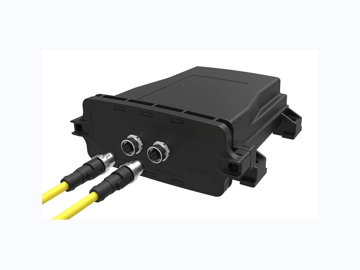
© PHOENIX CONTACT 2018-04-263778_en_A ECS... Data sheet 1D e s c r i p t i o n The Environmental Case System (ECS) is an enclosure system to protect devices from the elements in outdoor or indoor applications. The ECS... product line consists of a base and faceplate that are combined to make a complete enclosure system. The enclosure is available in two different locking methods: screw and mechanical latch. Both locking methods are available with or without a breather vent to alleviate pressure buildup when the enclosure is sealed and reduce condensation formation. Faceplates are available with a variety of connectors to meet various application requirements. A blank faceplate is available that can be customized to meet virtually any connector configuration. Wall, machine, and pole-mounting options allow flexibility for different applications. 3D housing data can be found at phoenixcontact.net/products. Make sure you always use the latest documentation. It can be downloaded at phoenixcontact.net/products. This document is valid for all products listed in the “Ordering data” on page 4 Electronic enclosures
ECS... 3778_en_A PHOENIX CONTACT 2/12 Table of contents
ECS... 3778_en_A PHOENIX CONTACT 3/12 2 Overview of the ECS... products Figure 1 Typical ECS... assembly (screw latch shown) The faceplate is available as a blank, with one or two M12 connectors, or a cable gland. The ECS... system provides two locking methods to secure the faceplate to the base. – Mechanical latch: No tools are required to secure the faceplate to the base, but a flat blade screwdriver is required to release the faceplate for removal. – Screw latch: Faceplate is secured to the base using screws that accept either a flat screwdriver or T20 Torx ® driver.
1 Base
2 Faceplate
3 Connector area
4 Mounting foot
5 Locking mechanism (screw shown)
6 Alignment tabs
7 Label area
ECS... 3778_en_A PHOENIX CONTACT 4/12 3O r d e r i n g d a t a
4 Technical data
Description Ty pe Order No. Pcs./Pkt. Base, mechanical latch, vented, black ECS-B-122X169-L-UV1-V 2230000 5 Base, mechanical latch, non-vented, black ECS-B-122X169-L-UV1-NV 2230001 5 Base, screw latch, vented, black ECS-B-122X169-S-UV1-V 2230002 5 Base, screw latch, non-vented, black ECS-B-122X169-S-UV1-NV 2230003 5 Faceplate, mechanical latch, blank, black ECS-P-122X169-L-UV1-B 2230004 5 Faceplate, mechanical latch, one M12 connector, black ECS-P-122X169-L-UV1-1M12 2230005 5 Faceplate, mechanical latch, two M12 connectors, black ECS-P-122X169-L-UV1-2M12 2230006 5 Faceplate, mechanical latch, one cable gland, black ECS-P-122X169-L-UV1-CG 2230007 5 Faceplate, screw latch, blank, black ECS-P-122X169-S-UV1-B 2230008 5 Faceplate, screw latch, one M12 connector, black ECS-P-122X169-S-UV1-1M12 2230009 5 Faceplate, screw latch, two M12 connectors, black ECS-P-122X169-S-UV1-2M12 2230010 5 Faceplate, screw latch, one cable gland, black ECS-P-122X169-S-UV1-CG 2230011 5 Base, mechanical latch, vented, gray ECS-B-122X169-L-UV-V GY 1050206 5 Base, mechanical latch, non-vented, gray ECS-B-122X169-L-UV-NV GY 1050212 5 Base, screw latch, vented, gray ECS-B-122X169-S-UV-V GY 1050209 5 Base, screw latch, non-vented, gray ECS-B-122X169-S-UV-NV GY 1050207 5 Faceplate, mechanical latch, blank, gray ECS-P-122X169-L-UV-B GY 1050386 5 Faceplate, mechanical latch, one M12 connector, gray ECS-P-122X169-L-UV-1M12 GY 1050385 5 Faceplate, mechanical latch, two M12 connectors, gray ECS-P-122X169-L-UV-2M12 GY 1050384 5 Faceplate, mechanical latch, one cable gland, gray ECS-P-122X169-L-UV-CG GY 1050383 5 Faceplate, screw latch, blank, gray ECS-P-122X169-S-UV-B GY 1050382 5 Faceplate, screw latch, one M12 connector, gray ECS-P-122X169-S-UV-1M12 GY 1050381 5 Faceplate, screw latch, two M12 connectors, gray ECS-P-122X169-S-UV-2M12 GY 1050379 5 Faceplate, screw latch, one cable gland, gray ECS-P-122X169-S-UV-CG GY 1050380 5 Accessories Description Ty pe Order No. Pcs./Pkt. Board lock ECS-BL 2230012 10 Pole-mounting kit ECS-PM 2230013 1 General data Ambient temperature, operating -40...85°C Ambient temperature, storage -40...85°C UL 94 flammability rating V0 Material Polycarbonate Color Black Power dissipation, Pv, at 20°C (horizontal mounting position) 19 W Degree of protection IP66/67/69 NEMA 250 enclosure rating 6
ECS... 3778_en_A PHOENIX CONTACT 5/12 5D i m e n s i o n s
5.1 External
UL 736C (Outdoor suitability) f1 UL 50/50E UL enclosure type1 4, 4X, 6 IEC 60068 (Vibration) 15g: 10-2000-10 Hz X, Y, Z for 2.5 h IEC 60068 (Shock) 50g, 20 pulses EN 50102 (Impact) IK08 IEC 60068 (Salt fog) 96 h 1 Enclosure components must be sold as a kit to apply mark. Contact local sales office for information. 196 161 110 148 A 180 Model Dimension “A” ECS-P-…-L-…1M12 (GY) 186 mm ECS-P-…-L-…2M12 (GY) 186 mm ECS-P-…-L-…CG (GY) 206 mm ECS-P-…-L-…B (GY) 176 mm 164 161 A 110 18064 148 Model Dimension “A” ECS-P-…-S-…1M12 (GY) 186 mm ECS-P-…-S-…2M12 (GY) 186 mm ECS-P-…-S-…CG (GY) 206 mm ECS-P-…-L-…B (GY) 176 mm
ECS... 3778_en_A PHOENIX CONTACT 6/12
5.2 Internal
Figure 4 Inside view of enclosur e 1.59 mm board Figure 5 Inside vi ew of enclosure 2.36 mm board B-B C-C A-A CC BB AA 3.75 7.67 9.06 27.56 99.97 12.88 31.22 113.13 117.9 32.6710.62 91.13 121.52 7.57 30.11 D-D E-E F-F FF EE DD 91.13 121.52 29.32 7.57 117.9 10.62 31.88 100.23 12.23 22.48 4.57 9.29 7.86 30.63 113.13
ECS... 3778_en_A PHOENIX CONTACT 7/12
5.3 PCB dimensions
Figure 6 Circuit board design dimensions and restrictions 121.0±0.3 109.0±0.3 92.0±0.3 25.4±0.3 10° 7.4±0.3 2.0±0.3 1.97±0.15 B Detail 1 2:1 66.1±0.3 128.2±0.3 92.6±0.3 Detail 1 131.9±0.3 D 87.0±0.3 91.0±0.3 14.45±0.3 104.0±0.3 A R15.0±0.3 E 9.2±0.3 ø5.32±0.15 A Component/Trace keep-out zone Maximum component height – Above PCB (1.57 mm PCB) = 12.5 mm – Above PCB (2.36 mm PCB) = 11.5 mm – Below PCB = 7.5 mm Maximum component height – Above PCB (1.57 mm PCB) = 30.5 mm – Above PCB (2.36 mm PCB) = 11.5 mm – Below PCB = 3.5 mm Maximum component height – Above PCB (1.57 mm PCB) = 30.5 mm – Above PCB (2.36 mm PCB) = 11.5 mm – Below PCB = No trace or components Maximum component height –A b o v e P C B = 2 9 . 5 m m – Below PCB = 9.5 mm A PCB mounting hardware hole B Optional cutout for ECS-BL (location and quantity determined by application) C Faceplate PCB connections D 1.57 mm PCB = 145.6 mm 2.36 mm PCB = 139.6 mm
ECS... 3778_en_A PHOENIX CONTACT 8/12 Figure 7 Label area
6 Connection technology
The ECS... enclosure provides for the use of any existing IP66/67 connection technology. 6.1 ECS-P...B faceplate The ECS-P...B faceplate is provided as a blank faceplate. It allows users to customize the faceplate to meet specific application requirements. – Add connector styles not currently available as a preconfigured faceplates from Phoenix Contact. – Combine connector styles for a specific application. For instance, combine two M12 connectors and one RJ45 connector. The ECS-P...B faceplate allows placement of connectors as desired within a certain area on the faceplate. The placement and number of connectors that can be added to the ECS-P…B (GY) is limited to within the area defined in Figure 8. Figure 8 Available connec tor area for ECS-P...B The available connector area is the same for both the mechanical latch and screw-type faceplates. 6.2 ECS-P...M12 faceplate ECS-P...M12 faceplates provide either one or two M12 connectors. The M12 connector is a two-piece system with a nut and insert. An M12 female coupling nut (Order No. 1552243) is provided for installation during assembly. Designers must order inserts separately for each specific application. Some of the common inserts are: 103
1432444 SACC-CI-M12FS-4CON-L 90 SH SCO
1436628 SACC-CI-M12FS-4CON-L90 SCO
1432457 SACC-CI-M12FSD-4CON-L90 SCO
1432431 SACC-CI-FS-5CON-L 90 SH SCO
1436644 SACC-CI-M12FS-5CON-L90 SCO
1437009 SACC-CI-M12FS-8CON-L90 SH SCO
1436990 SACC-CI-M12FS-8CON-L90 SCO
1424199 SACC-CI-M12FS-12CON-L90 SH
1424195 SACC-CI-M12FS-12CON-L90
1424201 SACC-CI-M12FS-17CON-L90 SH
1424197 SACC-CI-M12FS-17CON-L90
1424193 SACC-CI-M12FSY-8CON-L90
1424180 SACC-CI-M12FSX-8CON-L90
118.6 71.0 42.0 10.1
ECS... 3778_en_A PHOENIX CONTACT 9/12 Installation Figure 9 M12 connector installation 1. Position the connector housing (1) into the hole on the ECS-P...M12. 2. Thread the nut (2) on the opposite side and torque to 1.5 to 2.0 Nm. 3. Place the circuit board with the connector insert (3) into position on the ECS-P...M12 with the insert in the center of the connector housing. Secure the circuit board to the ECS-P...M12 (see 7.1 “Printed circuit board to faceplate assembly”). 4. Once the circuit board is secured to the faceplate, place the o-ring (4) inside the connector housing and over the connector insert. Slide the o-ring to the base of the insert. Use a small tool, if necessary. 6.3 ECS-P...CG faceplate ECS-P...CG faceplates provide a cable gland to allow a cable to pass directly into the enclosure and connect to the circuit board using one of Phoenix Contact’s PCB connectors. Installation The ECS-P...CG faceplate comes fully assembled. It accepts external cable diameters of 6 to 12 mm.
7 Installation
7.1 Printed circuit board to faceplate assembly
The printed circuit board must be secured to the faceplate before the faceplate is mated to the base. Figure 10 Circuit board placement 1. Place the circuit board (1) in position on the rear of the ECS-P... (2) and secure it with the flat washer (3) lockwasher (4) and screw (5) on both sides of the printed circuit board. 2. Torque the screws to 0.8 Nm.
7.2 Board lock (optional)
An optional board lock may be installed inside the base. The board lock prevents the printed circuit board and faceplate assembly from fully sliding out until the lock is released. This helps prevent a PCB assembly from dropping out of the base during disassembly. NOTE: Avoid all radial forces between the connector inserts attached to the circuit board and any connector housings in the faceplate. Axial forces 80 Nm are acceptable. Use webcode #391 at PhoenixContact.com to review the available PCB terminal blocks. Use webcode #425 at PhoenixContact.com to review the available PCB connectors. Search for 1411133 at PhoenixContact.com for additional details regarding the cable gland. For ECS-P...M12 faceplates, the M12 connector(s) must be installed on the faceplate prior to attaching the printed circuit board. The printed circuit board design must include a notch for the board lock to function. Without the notch, the board lock is ineffective. PC
ECS... 3778_en_A PHOENIX CONTACT 10/12 Board locks may be installed on one or both sides. 1. Orient the board lock (1) so the side with the lance is on the outside as shown. Figure 11 Board lock 2. Align the board lock with the slot in the base. 3. Slide the board lock into the slot until a click is heard. 4. If board locks are desired for both sides, repeat the process for the other side.
7.3 Faceplate and base
7.3.1 Assembly
- Align the printed circuit bo ard with the slots in the enclosure (ECS-B…). 2. Gently slide the printed circuit board and ECS-P… assembly (2) into the enclosure (ECS-B…). 3. There are six tabs on the enclosure face (3) (ECS-B…). The tabs must engage the six slots in the ECS-P… (4) to ensure a proper seal. 4. Secure the faceplate (ECS-P…) to the enclosure (ECS- B…). a) ECS-P…-L…: Press the faceplate (ECS-P…) to the enclosure (ECS-B…) until the two latches on the side are secure. b) ECS-P…-S…: Torque the two screws to 0.8 Nm using either a T20 Torx bit or blade-style screwdriver.
7.3.2 Disassembly
- Insert a flat-blade screwdriver (maximum shaft diameter of 3.5 mm) straight into the square hole in the ECS-P... (A). Do not pry! 2. Using only a finger, pull on the tab on the screwdriver side of the ECS-P... until the latch releases slightly (B). 3. Insert the screwdriver into th e other side of the ECS-P... and pull up on the tab until the latch releases. 4. With both latches rele ased, pull the ECS-P... and printed circuit board assembly straight from the base (C). 1. Using a screwdriver or T20 Torx driver, turn the screws screw disengages from the threads on the ECS-B.... 2. Pull the ECS-P... and PCB a ssembly straight from the base. CA B
ECS... 3778_en_A PHOENIX CONTACT 11/12
7.3.4 With optional board lock
Figure 13 Board lock release If the optional ECS-BL is installed, follow the normal opening procedures. When the ECS-BL engages the notches in the printed circuit board and halts removal, insert a small tool to hold the lock open before continuing to remove the assembly.
7.4 Mounting
The ECS... may be mounted directly to a wall or mounted to a pole using the optional ECS-PM pole mount kit (Order No. 2230013).
7.4.1 Direct mounting
When direct mounting the ECS..., the integrated mounting feet are used. The base accepts mounting hardware up to 5 mm diameter. Use the base as a template or refer to Figure 2 and Figure 3.
7.4.2 Pole mounting
The ECS... may be mounted to a round or square pole with a pole diameter of 5 to 15 cm using the ECS-PM pole mounting kit. This kit allows attachment to a pole using either hose clamps or bolts. The ECS-PM is comprised of two part A and two part B components. Each part A joins with a part B and slides onto the mounting feet of the base. Attachment to the base Figure 14 ECS-PM assembly 1. Take part A and partially slid e it onto one mounting foot of the housing (1). 2. Take part B and partially slide in onto the opposite mounting foot of the housing. 3. Part A and part B will intersec t. Slide each part together until they are fully engaged and come against the stop on the mounting feet. 4. Repeat steps 1 though 3 for the second pair of parts A and B. 5. If the assembly is to be mounted using bolts through the standoffs, secure the part A and B pairs to the housing using M5 (3/16-in.) hardware (2) in four places. Mounting hardware is not included and must be obtained locally. Select hardware that is appropriate for the mounting surface. Hardware and hose clamps, if required, must be purchased locally for the application mounting surface. The maximum hose clamp width is 13 mm). A B A B