

 Download PDF
218_08 CTS
Document overview
- PDF pages: 2
Technical content
Page 1
®
SMT Hfla Pctih DI
P
Swctih–Auto Palceaelb
Features
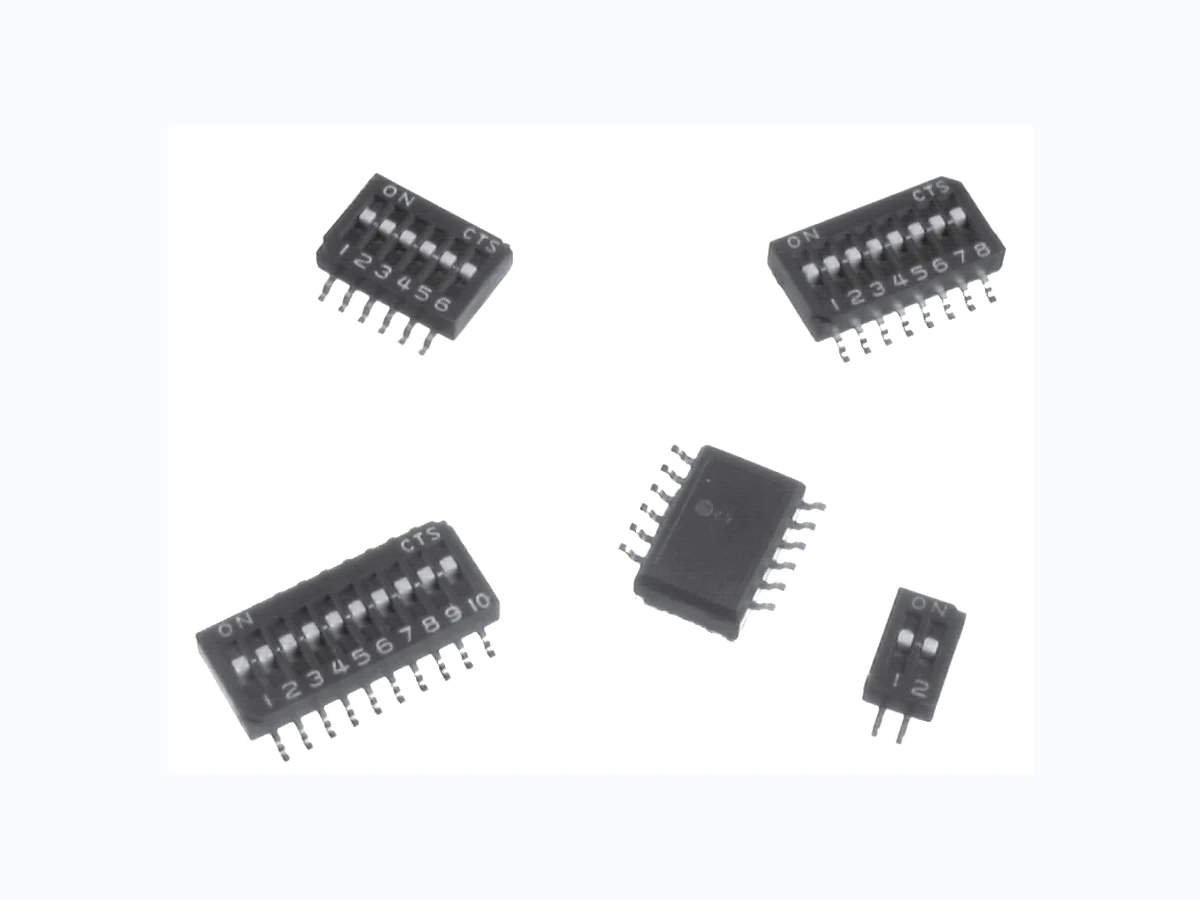
Optimized Mechanical Features
- Removable tape seal to withstand IR vapor phase or wave soldering temperatures and board washing
- Gull-wing and "J" bend terminal configurations
- Low profile actuators prevent accidental actuation SPST congifuraoitn avaliaelb
Optimized Contact System
- Redundant, wiping contact
- Contactor does not deflect during actuation
- 0.6 mm/.024" actuator travel
Materials
- Gold plated beryllium copper contacts
- Gold flash coated terminals
- High temperature materials (UL94V-0)
- RoHS Compliant
Electrical and Mechanical Specifications
Swtich Funciton SPST - 2, 4, 6, 8, 12 positions Swtich Contact Resistance 100 moillihms maixmum laitini 100 moillihms maixmum at end oefilf Insulaiton Resistance 100 megohms minimum between insulated terminals Dileeccirt Srtength 350 VAC for 1 minute between adjacent swithces Nonswtiching Raitng 100 mA or 50 VDC maixmum Swtich Capaticance 10 pF maixmum between aajdcent closed switches Operaitng T
emperature - 55°C to +85°C Actuaiton Lfie 1,000 cyelcs swctinihg 25 mA @ 24 VDC

Coplanatiry Coalpnaytir of 0.1mm./004" maixmum Allowable Solder Time Up to 60 seconds at 260°C Vibraiton Per MIL-STD-202G, method 204D, condition B .(06" or 15Gs’ between 10 HZ to 2 KHz) wtih no contanitccontsiseneics greater than 1 mcirosecond. Shock Per MIL-STD-202G, method 213B, condition A (50Gs’) wtih no contanitccontsiseneics greater than 1 mcirosecond. Seilang Standard bottom sela Opoitntlaop tape sela Marikng Spelaic marnikg avaliaelb-constlu CTS Packaging Standard : Anti-static tube packaging Opoitnla : Tape and reel packaging
© 2008 CTS Corporation. All rights reserved. Information subject to change.
1 - 2
2/19/08
CTS Electronic Components
www.ctscorp.com
Page 2
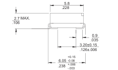
CTS SERIES 218LPJ - "J" Bend Terminal
DIM "A"
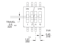
TRAVEL 0.6 .024
MOUNTING SURFACE
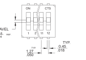
SURFACE MOUNT PAD LAYOUT
TABLE 1
TYP.
| NO. OF SWITCH POSITIONS | "A" OVERALL DIMENSIONS |
| 2 | 3.71/.146 |
| 4 | 6.25/.246 |
| 6 | 8.79/.346 |
| 8 | 11.33/.446 |
| 10 | 13.87/.546 |
| 12 | 16.41/.646 |
1.27 .050
1.27 .050 0.51 .021
5.37 .211
0.76 .030
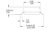
CTS SERIES 218LP - Gull Wing Terminal
SURFACE MOUNT PAD LAYOUT
TYP. 1.27 .050 0.51 1.27 .020 .050
8.89 .350
0.76 .030
Ordering Information
– 12
218
LP S T
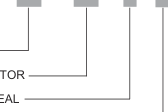
XX: NO. OF POSITIONS
LP: LOW PROFILE ACTUATOR
S: BOTTOM SEAL
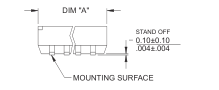
TABLE 2
| NO. OF SWITCH POSITIONS | "A" OVERALL DIMENSIONS |
| 2 | 3.71/.146 |
| 4 | 6.25/.246 |
| 6 | 8.79/.346 |
| 8 | 11.33/.446 |
| 10 | 13.87/.546 |
| 12 | 16.41/.646 |
DIMENSION: mm inch
F J R
BLANK: SHIP AT ON POSITION F: SHIP AT OFF POSITION
BLANK : ANTI-STATIC TUBE PACKAGING R : TAPE AND REEL PACKAGING
BLANK : GULL WING TERMINAL J: J BEND TERMINAL BLANK : NO TOP TAPE SEAL T : TOP TAPE SEAL
© 2008 CTS Corporation. All rights reserved. Information subject to change.
2/19/08
CTS Electronic Components
www.ctscorp.com