
DATASHEET SEARCH SITE
Document overview
- Manufacturer or author: Provided By digicamel.com
- PDF pages: 3
Technical content
Features
Electrical Characteristics for Series % of Ampere Rating Ampere Rating Opening Time 210% 1A - 3.15A 30 minutes, Maximum 4A - 6.3A 30 minutes, Maximum 8A - 10A 30 minutes, Maximum 275% 400% 1000%
Applications
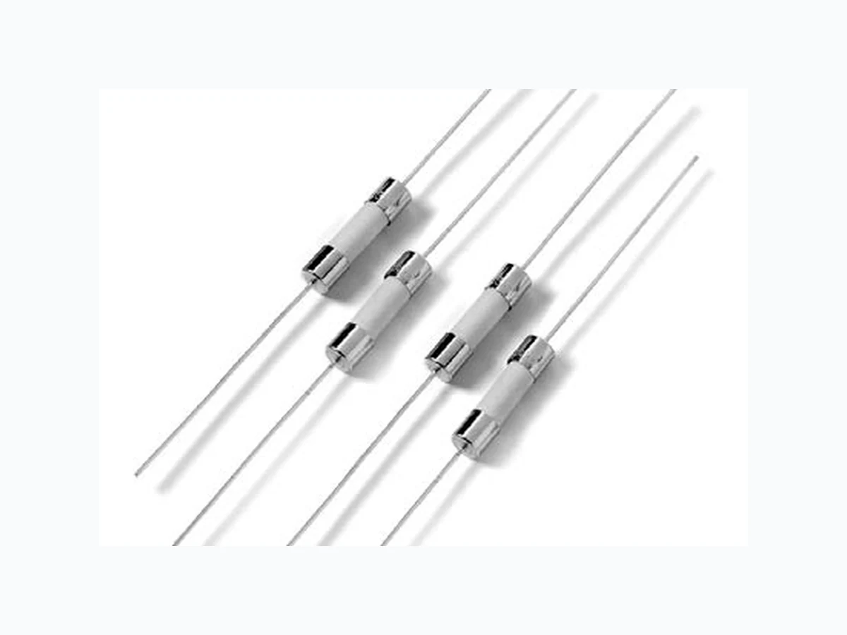
5x20mm Time-Lag surge withstand ceramic body cartridge fuse designed to IEC specification t %FTJHOFEUP International (IEC) Standards for use globally t .FFUTUIF*&$ 60127-2, Sheet 5 specification for Time-Lag Fuses t )JHICSFBLJOHDBQBDJUZ t "WBJMBCMFJOBYJBMMFBE form t 3P)4DPNQMJBOUBOE Pb-free Used as supplementary protection in appliance or VUJMJ[BUJPOFRVJQNFOUUPQSPWJEFJOEJWJEVBMQSPUFDUJPOGPS components or internal circuits. PS E
Description
(Ohms) Nominal Melting I2t (A2 sec) Maximum Voltage Drop at Rated Current (mV) Maximum Power Dissipation at Rated Current (W) Agency Approvals PS E 001 . 1 250
1500 A @
250 VAC
0 . 1 5 1 5 1 . 5 2 0 0 0 3 5 0 2 . 5 xxxxxxx 002. 2 250 0.0566 11 .68000 190 2.5 xxxxxxx 3.15 3.15 250 0.0283 43.25500 140 4 xxxxxxx 004. 4 250 0.0185 46.96000 100 4 x x x x x x x 005. 5 250 0.0153 66.09500 100 4 xxxxxxx 06.3 6.3 250 0.0108 128.75000 100 4 xxxxxxx 008. 8 250 0.0092 209.88000 100 4 x xxxxx 010. 10 250 0.0066 333.56500 100 4 x x x x Electrical Characteristic Specifications by Item Revised: February 14, 2011
Introduction to Circuit ProtectionIntroduction to Circuit Protection Transientology 2 © 2009 Littelfuse, Inc. Specifications are subject to change without notice. Axial Lead Fuses 215SP Series 5×20 mm > Time-Lag > 215SP Series Please refer to www.littelfuse.com/series/215SP .html for current information. Average Time Current Curves Soldering Parameters - Wave Soldering Dwell Time 100 120 140 160 180 200 220 240 260 280 300 100 110 120 130 140 150 160 170 180 190 200 210 220 230 240 Time (Seconds) Temperature (°C) - Measured on bottom side of board Cooling TimePreheat Time Wave Parameter Lead-Free Recommendation Preheat: %FQFOETPO'MVY"DUJWBUJPO5FNQFSBUVSF (Typical Industry Recommendation) Temperature Minimum: 100° C Temperature Maximum: 150° C Preheat Time: 60-180 seconds Solder Pot Temperature: 260° C Maximum Solder Dwell Time: 2-5 seconds Recommended Hand-Solder Parameters: Solder Iron Temperature: 350° C +/- 5°C )FBUJOH5JNFTFDPOETNBY Note: These devices are not recommended for IR or Convection Reflow process. Recommended Process Parameters: 215001. 2151.25 21501.6 215002. 21502.5 2153.15 215004. 215005. 21506.3. 215010. 215008. 0.001 0.01 0.1 100 1000 10000 0.01 0.1 1 10 100 Time (seconds) Amps T emperature Rerating Curve
3© 2009 Littelfuse, Inc. Specifications are subject to change without notice. Axial Lead Fuses 215SP Series 5×20 mm > Time-Lag > 215SP Series Please refer to www.littelfuse.com/series/215SP .html for current information. 215SP Series "BOE"IBWFNNEJBNFUFS Dimensions 5.1 ± 0.6 20 ± 0.5 5.1 ± 0.6 Packaging Packaging Option Packaging Specification Quantity Packaging Code Reel Size 215SP Series #VML N/A 1000 MXE N/A Part Numbering System 0215 xxxx M X E SP P Series Amp Code Refer to Amp Code column of Electrical Characteristics Table Lead-free Single Pigtail Quantity Code M = 1000 Option Codes Blank : Cartidge Type Fuse E : Axial Lead Fuse Packaging Code X = Filler Materials Body: Ceramic Cap:/JDLFMoQMBUFE#SBTT Leads: Tin–plated Copper T erminal Strength MIL -STD-202G, Method 211A, Test Condition A Solderability Reference IEC 60127 Second Edition 2003-01 Annex A Product Marking Cap 1:#SBOEMPHP DVSSFOUBOEWPMUBHF ratings Cap 2:"HFODZBQQSPWBMNBSLT Product Characteristics Operating Temperature –55ºC to +125ºC Thermal Shock MIL -STD-202G, Method 107G, Test Condition B (5 cycles, –65ºC to +125ºC) Vibration MIL -STD-202G, Method 201A Humidity MIL -STD-202G, Method 103B, Test $POEJUJPO" )JHI3) BOE FMFWBUFEUFNQ $ GPSIPVST Salt Spray MIL -STD-202G, Method 101D, Test Condition B