
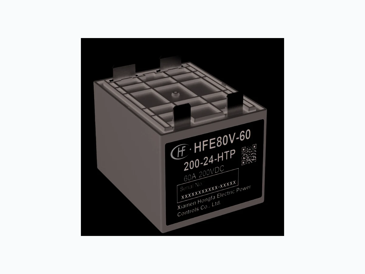
HFE80V-60 KG
Document overview
- PDF pages: 4
Technical content
Page 1
HIGH VOLTAGE DC RELAY
- 60A, 200Vdc - 1 Form A Relay
- 3kVac dielectric strength between coil and contacts
- Different control coil voltages: 12, 24Vdc
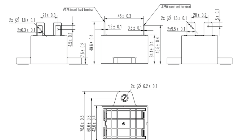
- Outline Dimensions: (42.6x55.1x45.5) mm
- Dimensions with flanges: (76.6x55.1x45.5) mm
- Quick Connect terminals
- Mounting flanges reinforced with compression sleeves
- RoHS compliant materials and processes
Contact Data
Rated Load
60A @ 200VDC
Contact form
1 Form A
Contact material
Cu Alloy
Contact resistance\*
≤1.5mΩ (at 20A) †
Max. switching voltage
250Vdc
Max. switching current
100A
Set time
≤ 30ms
Reset time
≤ 10ms
Bounce time
≤ 5ms 10,000 cycles §
Electrical endurance Mechanical endurance
200,000 cycles
Coil power consumption 3W
A
HFE80V-60
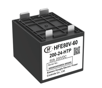
Characteristics
Insulation resistance 1,000MΩ (at 500 Vdc) Dielectric strength: Coil to contact
3kVac for 1 min.
Across open contacts 2kVac for 1 min. Dielectric creepage Ambient temperature -40°C to +85°C Ambient humidity
5% - 85% RH
Vibration
1.5 mm (DA) 10 Hz to 500 Hz ‡
Shock resistance:
196 m/s2 \*\*
Functional
490 m/s2 ††
Destructive Termination: Coil termination
Quick Connect terminals
Load termination
Quick Connect terminals
Unit Weight
Approximately 175g
\* Typical value for Initial Contact Resistance: Using a sample quantity of at least 20 units, take the average value from 5 continuous measurements from each sample
† Rating at 23°C
‡ Acceleration of 49ms2, 8 hours each for both directions on of three mutually perpendicular axes,4 hours each for the energized and non-energized status, total 24 hours. There shall not be any abnormalities on relay appearance, construction and performance
§ Rating at: 150Vdc / 60A
\*\* Duration 11ms, 500 ops for each direction of three mutually perpendicular axes, 250 ops each for the energized and nonenergized status, total 3000 shocks
†† Duration 6ms, 50 shocks for each direction of three mutually perpendicular axes, total 300 shocks
Page 2
Current Endurance‡‡
Current
Duration
60A
Continuous
90A
12 min
180A
15 s
600A
1 s
‡‡ Testing Conditions: 1V, 85°C, 15 mm2 cable used
Electrical Endurance§§
Contact Rating
Contact Rating
Operations
| Switching: Steady 60A Contact Voltage: 12Vdc | 0.6s/5.4s | 100,000 ops |
| Switching: Steady 60A Contact Voltage: 48Vdc | 50,000 ops | |
| Switching: Steady 60A Contact Voltage: 72Vdc | 30,000 ops | |
| Switching: Steady 60A Contact Voltage: 150Vdc | 10,000 ops | |
| Switching: Steady 10A Contact Voltage: 150Vdc | 75,000 ops | |
| Switching: Steady 60A Contact Voltage: 200Vdc | 5,000 ops |
§§23oC room temperature
Coil Resistance
Nominal Coil Voltage
Pick-up Voltage
12Vdc
≤9Vdc
24Vdc
≤18Vdc
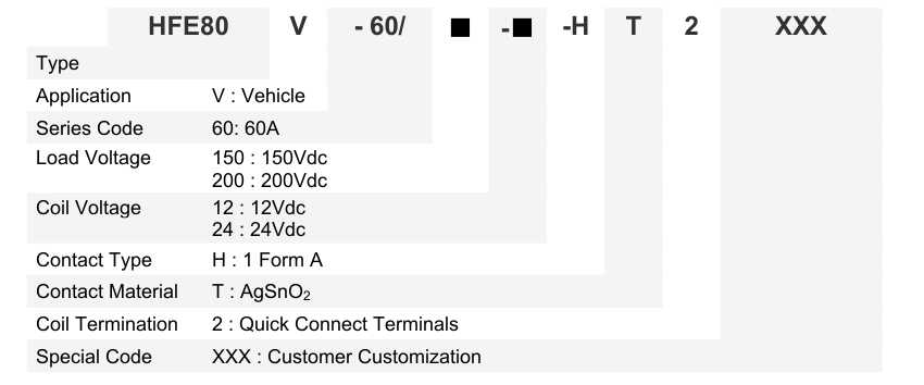
Ordering Information
(Ω±10%) at 23°C
Drop-out Voltage
Coil Resistance
≥1Vdc
48Ω
≥2Vdc
192Ω
A
Page 3
Dimensional Drawings
(Unit: mm)

Wiring Diagrams
Single Coil
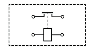
- Coil is polarity independent 2. Load connections are polarity independent
A
Page 4
Application Notes
- To maintain the relay in its closed state, the coil voltage should reach the stated pick-up voltage. 2. For definitions of terms used in this data sheet, see glossary at www.kgtechnologies.net.

Disclaimer: This data sheet is for reference only. All specifications are subject to change without prior notice. KG Technologies, Inc. cannot predict every possible application for our relays. While we do our best to make our relays as versatile as possible, we highly recommend contacting our engineering team if you have any questions. KG Technologies, Inc. is not responsible for malfunctioning relays when operated outside the specified parameters given in this data sheet.
A