

 Download PDF
V23072-A1061-A303 MACOM
Document overview
- Manufacturer or author: Provided By digicamel.com
- PDF pages: 6
Technical content
Features
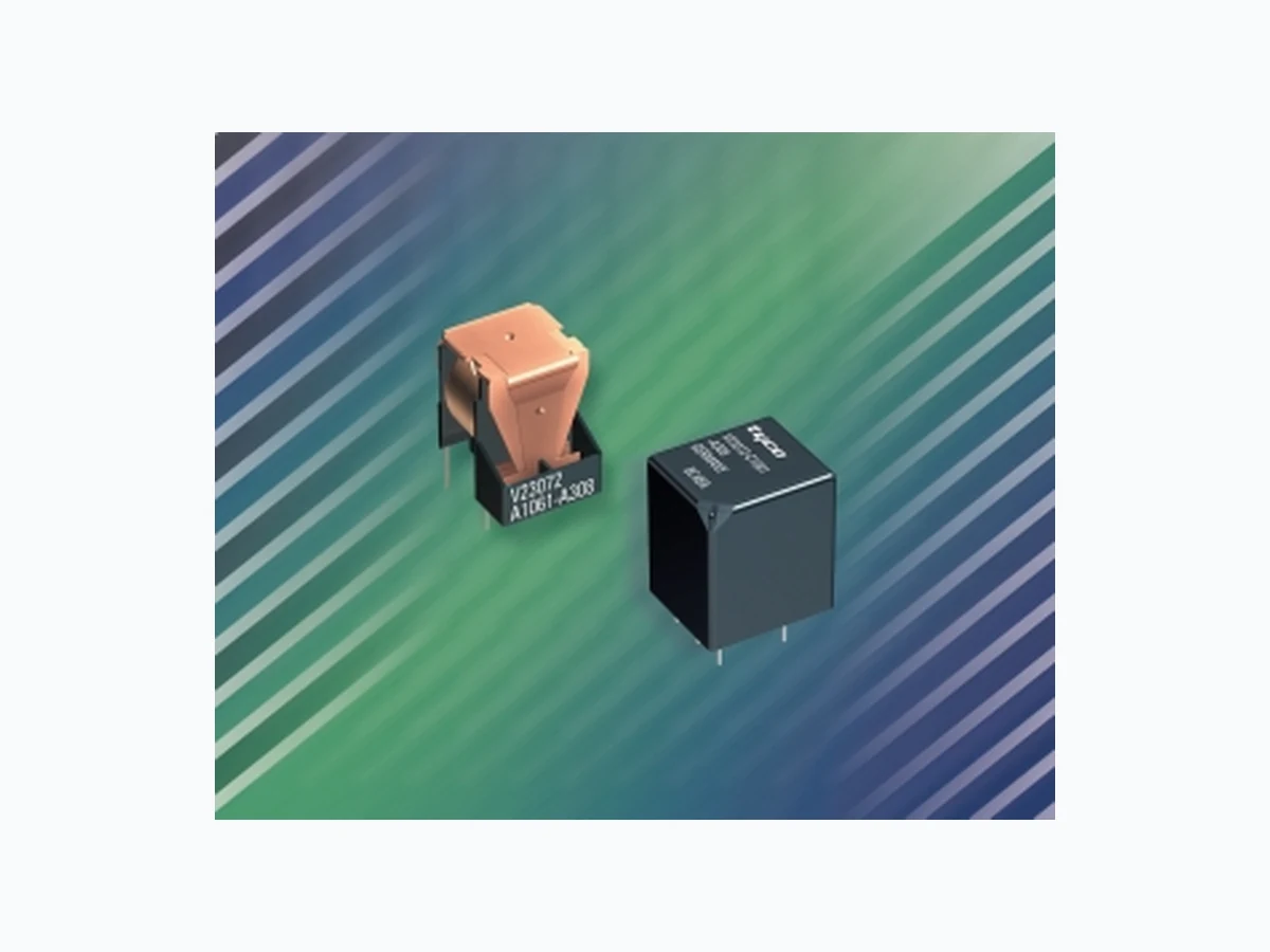
- 60% smaller volume than power relay K - High switching capacity - Small footprint, minimal space requirements Typical applications - Lamp control circuits - Indicator control circuits - Sunroof motors - Window motors - Immobilizers - Central doorlock etc. - Also available for 42 V
applications
Please contact Tyco Electronics for relay application support. Design Open or sealed; sealed version: sealing in accordance with IEC 68; immersion cleanable: protection class IP 67 to IEC 529 (EN 60 529) Weight Approx. 0.28 oz. (8 g) open version Approx. 0.32 oz. (9 g) sealed version Nominal voltage
12 V or 24 V;
other nominal voltages on request Terminals PCB terminals, for assembling in printed circuit boards Terminals in grid 0.049 … 0.050" (1.25 … 1.27 mm) Conditions All parametric, environmental and endurance tests are performed according to EIA Standard RS-407-A at standard test conditions unless otherwise noted: 23 ° C ambient temperature, (998.9 ±33.9 hPa). Please also refer to the Application Recommendations in this catalog for general precautions. Disclaimer All technical performance data apply to the relay as such, specific conditions of the individual application are not considered. Please always check the suitability of the relay for your intended purpose. We do not assume any responsibility or liability for not complying herewith. We recommend to complete our questionnaire and to request our technical service. Any responsibility for the application of the product remains with the customer only. All speci fications are subject to change without notification. All rights of Tyco are reserved.
Mini power relay K (open) Please observe the disclaimer. 101 Catalog 1308028 Issued 01-05 Dimensional drawing Open version Terminals tinned additional tin tops Tyco0595-Z Ø .138 (3.5) .689 ±.020 (17.5 ±0.5) .138 ±.012 *) (3.5 ±0.3) .157 ±.039 (4 ±1) .035 ±.006 (0.9 ±0.15) .008 … .055 (0.2 … 1.4) .374 ±.008 (9.5 ±0.2) .264 ±.012 (6.7 ± 0.3) .240 ±.012 (6.1 ± 0.3) .512±.008 (13.0 ±0.2) .591 ±.039 (15 ±1) .571 ±.016 (14.5 ±0.4) max .039 inch (1 mm) ECR2209-U .033 ±.002 (0.85 ±0.06) Ø .033 ±.002 (0.85 ±0.05) .030 ±.002 (0.75 ±0.06) .022 ±.002 (0.55 ±0.05) View of the terminals (Bottom view) Tyco0596-8 .039 ±.018 (1 ±0.45) .091 max. (2.3 max.) .056 ±.010 (1.42 ±0.25) .047 ±.016 (1.2 ±0.4) Ø .512 +.004 (1.25 … 1.27) Mounting holes View of the terminals (Bottom view) Grid 0.049 … 0.050" (1.25 … 1.27 mm)
Mini power relay K (sealed) Please observe the disclaimer. 102 Catalog 1308028 Issued 01-05 Dimensional drawing Sealed version Terminals tinned The Nipp-off-pin may be removed after soldering and washing (for ventilation) additional tin tops Nipp-off-pin Tyco1112-3 .756 ±.012 (19.2 ±0.3) .118 ±.012 *) (3 ±0.3) .012 ±.008 (0.3 ±0.2) .018 ±.016 (0.45 ±0.4) .579 ±.012 (14.7 ±0.3) .665 ±.012 (16.9 ±0.3) max .039 inch (1 mm) ECR2210-X .033 ±.002 (0.85 ±0.06) .181 ±.008 (4.6 ±0.2) .033 ±.002 (0.85 ±0.06) 2 x Ø .033 ±.002 (Ø 2 ±0.1) .075 ±.008 (1.9 ±0.2) .354 ±.008 (9 ±0.2) .030 ±.002 (0.75 ±0.06) 4 x .022 ±.002 (0.55 ±0.05) View of the terminals (Bottom view) ECR0598-P .106 ±.016 (2.7 ±0.4) .094 ±.024 (2.4 ±0.6) Ø .512 +.004 (1.25 … 1.27) Mounting holes View of the terminals (Bottom view) Grid 1.25 … 1.27 mm Assembly and positioning aid
Mini power relay K (open and sealed) Please observe the disclaimer. 103 Catalog 1308028 Issued 01-05 Contact data Typical areas of application Contact configuration Circuit symbol (see also Pin assignment) Rated voltage Rated current at 85 ° C Contact material Max. switching voltage/power Max. switching current1) On2) Off Min. recommended load5) Voltage drop at 10 A (initial) for NC/NO contacts Mechanical endurance (without load) Electrical endurance (example of resistive load) 1) The values apply to a resistive load or inductive load with suitable spark suppression. 2) For a load current duration of maximum 3 s for a make/break ratio of 1:10. 3) Corresponds to the peak inrush current on initial actuation (cold filament). 4) At 50 % ON period 5) See chapter Diagnostics in our Application Recommendations on page 18. Resistive / inductive loads Indicator lamps Make Changeover Double Make Double contact/ contact/ make contact/ contact/ make contact/ Form A Form C Form U Form A Form U 12 V
10 A 5 A/10 A 2 x 6 A 5 A 2 x 5 A
AgNi0.15 AgSnO 2 See load limit curve NC/NO
60 A 12 A/60 A 2 x 40 A 60 A 3) 120 A3)
20 A 10 A/20 A 2 x 20 A 6 A 12 A
1 A at 5 V
107 operations > 2 x 10⁵ operations > 1,5 x 10 6 > 1.5 x 10⁶ 10 A, 13.5 V operations operations up to 3 x 21 W up to 6 x 21 W 3 5 Load limit curve Pin assignment (open and sealed) 1 make contact/ 1 double make contact/ 1 changeover contact/ 1 form A 1 form U 1 form C Load limi curve 1 Load limi curve 2 Load limi curve 3 Tyco Load limit curve 1 ^= safe shutdown, connected as form X, load on pin 5 and 7 Load limit curve 2 ^= safe shutdown, no stationary arc / make contact Load limit curve 3 ^= arc extinguishes during transit time (changeover contact) Load limit curve 1 Load limit curve 2 Load limit curve 3 Tyco0626-Y
Mini power relay K (open and sealed) Please observe the disclaimer. 104 Catalog 1308028 Issued 01-05 Coil data Available for nominal voltages 12, 24 V (other coils on request) Nominal power consumption of the unsuppressed coil at nominal voltage 1.1 W Test voltage winding/contact 500 VACrms Maximum ambient temperature range1) – 40 to + 85 ° C Operate time at nominal voltage 2) Typ. 3 ms Release time at nominal voltage Typ. 1.5 ms 1) See also operating voltage range diagram 2) Measured at nominal voltage without coil suppression unit N.B. A low resistive suppression device in parallel to the relay coil increases the release time and reduces the lifetime caused by increased erosion and/or higher risk of contact tack welding. Mechanical data Enclosure Sealed relay is suitable for immersion cleaning of PCB assembly or conformal coating. Sealed Please refer to the Application Recommendations in this catalog. Operating voltage range Does not take into account the temperature rise due to the contact current E = pre-energization Operating conditions Temperature range, storage -40 ° C to 155 ° C Test Relevant standard Testing as per Dimension Comments Climatic cycling with condensation1) EN ISO 6988 20 cycles Storage 8/16 h Temperature cycling1) IEC 68-2-14 Na 20 cycles – 40/+ 85 ˚C (dwell time 1 h) Damp heat1) constant IEC 68-2-3 Ca 56 days Upper air temperature 55 ° C Corrosive gas1) IEC 68-2-42 10 days IEC 68-2-43 – 10 days Vibration resistance IEC 68-2-6 (sine pulse form) 10 … 200 Hz No change in the acceleration, acc. to position 23 … 35 g switching state > 10 µs Shock resistance IEC 68-2-27 (half-sine pulse form) 4 … 6 ms No change in the acceleration 23 … 280 g switching state > 10 µs Solderability IEC 68-2-20 Ta, Method 1 Aging 3 (4 h/155 ° C) Dewetting Resistance to soldering heat IEC 68-2-20 Tb, Method 1A 10 s ± 1 s with thermal screen Sealing1) IEC 68-2-17 Qc, Method 2 1 min / 70 ° C Flammability UL94-HB 1) only sealed version
Mini power relay K (open and sealed) Please observe the disclaimer. 105 Catalog 1308028 Issued 01-05
Ordering information
Standard delivery packs (orders in multiples of delivery pack) Mini K open: 600 pieces Mini K sealed: 504 pieces Coil Rated coil Coil resistance Must Must Allowable overdrive 1) data for voltage +/- 10% operate voltage release voltage voltage (V) Mini K (V) ( Ω ) (V) (V) at 23 °C at 85 °C Open and sealed V23072-061-** 12 130 6.9 1.2 19.2 14.9 1) Allowable overdrive is stated with no load applied and minimum coil resistance. Part numbers (see table below for coil data) Contact Contact Enclosure Terminals Relay part number Tyco order number arrangement material V23072-A1061-A303 3-1393272-2 Form C AgNi0.15 Open Printed circuit V23072-A1062-A303 5-1393272-2 Form C AgNi0.15 Open Printed circuit V23072-A1061-A308 3-1393272-6 Form U, X AgNi0.15 Open Printed circuit V23072-A1062-A308 5-1393272-3 Form U, X AgNi0.15 Open Printed circuit V23072-C1061-A302 4-1393273-9 Form A AgNi0.15 Sealed Printed circuit V23072-C1062-A302 7-1393273-6 Form A AgNi0.15 Sealed Printed circuit V23072-C1061-A303 5-1393273-0 Form C AgNi0.15 Sealed Printed circuit V23072-C1062-A303 7-1393273-8 Form C AgNi0.15 Sealed Printed circuit V23072-C1061-A308 6-1393273-0 Form U, X AgNi0.15 Sealed Printed circuit V23072-C1062-A308 8-1393273-2 Form U, X AgNi0.15 Sealed Printed circuit V23072-C1061-A402 2-1416001-0 Form A AgSnO2 Sealed Printed circuit V23072-C1061-A408 1-1416001-4 Form U, X AgSnO2 Sealed Printed circuit