

 Download PDF
DATASHEET SEARCH SITE
Document overview
- Manufacturer or author: Provided By digicamel.com
- PDF pages: 5
Technical content
06-2011, Rev. 0611 www.te.com © 2011 Tyco Electronics Corporation, a TE Connectivity Ltd. company. Datasheets and product specification ac- cording to IEC 61810-1 and to be used only together with the ‘Definitions’ section. Datasheets and product data is subject to the terms of the disclaimer and all chapters of the ‘Definitions’ section, available at http://relays.te.com/definitions Datasheets, product data, ‘Definitions’ sec- tion, application notes and all specifications are subject to change. n Small power relay n Limiting continuous current 30A n Minimal weight n Low noise operation n Wave (THT) and reflow (THR/pin-in-paste) solderable versions n For twin version refer to Double Micro Relay K Typical applications Car alarm, door control, door lock, hazard warning signal, heated front/rear screen, immobilizer, lamps front/rear/fog light, interior lights, seat control, sun roof, turn signal, window lifter, wiper control. Micro Relay K (THT – THR) Automotive Relays PCB Single Relays Contact Data Typical applications Resistive/inductive load Wiper load Lamp load5) V23086-*100*-A403 V23086-*1*02-A803 V23086-***21-A502 Contact arrangement 1 form C, 1 CO 1 form C, 1 CO 1 form A, 1 NO Rated voltage 10/12VDC 10/12VDC 10/12VDC NO/NC NO/NC Rated current 30/25A 30/25A 30A Limiting continuous current 23°C 30/25A 30/25A 30A 85°C 20/15A 20/15A 20A Limiting making current 40A1) 40A 1) 100A2) Limiting breaking current 30A 30A 30A Contact material AgSnO2 Min. recommended contact load 1A at 5VDC3) Initial voltage drop at 10A, typ./max. 30/300mV Operate/release time typ. 3/1.5ms4) Electrical enduranc cyclic temperature -40°C, +25°C, +85°C form C contact (CO) at 14VDC motor reverse blocked, wiper, 25A, 0.77mH 25A make/5A break, >1x10⁵ ops. generator peak, 20A on NC,1mH >1x10⁶ ops. form A contact (NO) at 14VDC resistive 20A lamp 100A inrush, >3x10⁵ ops. 10A steady state >1x10⁵ ops.5) Mechanical endurance >5x10⁶ ops. Max. DC load breaking capacity Load limit curve 1: arc extinguishes, during transit time (changeover contact). Load limit curve 2: safe shutdown, no stationary arc (make contact). Load limit curves measured with low inductive resistors verified for 1000 switching events. 1) The values apply to a resistive or inductive load with suitable spark suppression and at maximum 13.5VDC for 12VDC load voltages. For a load current duration of maximum 3s for a make/break ratio of 1:10. 2) Corresponds to the peak inrush current on initial actuation (cold filament). 3) See chapter Diagnostics of Relays in our Application Notes or consult the internet at http://relays.te.com/appnotes/ 4) Measured at nominal voltage without coil suppression unit. A low resistive suppression device in parallel to the relay coil increases the release time and reducesthe lifetime caused by increased erosion and/or higher risk of contact tack welding. 5) Be aware of using right polarity, see Terminal Assignment. Wrong polarity will reduce endurance. 086C/R1_fcw1b
06-2011, Rev. 0611 www.te.com © 2011 Tyco Electronics Corporation, a TE Connectivity Ltd. company. Datasheets and product specification ac- cording to IEC 61810-1 and to be used only together with the ‘Definitions’ section. Datasheets and product data is subject to the terms of the disclaimer and all chapters of the ‘Definitions’ section, available at http://relays.te.com/definitions Datasheets, product data, ‘Definitions’ sec- tion, application notes and all specifications are subject to change. Micro Relay K (THT – THR) (Continued) Automotive Relays PCB Single Relays Other Data EU RoHS/ELV compliance compliant Ambient temperature, DC coil -40 to +105°C Cold storage, IEC 60068-2-1 1000h; -40°C Dry heat, IEC 60068-2-2 1000h; +125°C Climatic cycling with condensation, EN ISO 6988 20 cycles, storage 8/16h Temperature cycling (shock), IEC 60068-2-14, Na 100 cycles; -40/+125°C Temperature cycling, IEC 60068-2-14, Nb 35 cycles; -40/+125°C Damp heat cyclic, IEC 60068-2-30, Db, variant 1 6 cycles 25°C/55°C/93%RH Damp heat constant, IEC 60068-2-3 method Ca 56 days 40°C/95%RH Degree of protection THT: RT III (61810), IP67 (IEC 60529) THR: RT II (61810), IP56 (IEC 60529) Sealing test, IEC 60068-2-17: THT Qc, method 2, 1min, 70°C Corrosive gas IEC 60068-2-42 10 days IEC 60068-2-43 10 days Vibration resistance (functional) IEC 60068-2-6 (sine sweep) 10 to 500Hz; 6g Shock resistance (functional) IEC 60068-2-27 (half sine) 6ms, up to 30g6) Terminal type PCB:THT, THR Weight approx. 4g (0.14oz) Solderability (aging 3: 4h/155°C) THT IEC 60068-2-20 Ta, method 1, hot dip 5s, 215°C Solderability THR IEC60068-2-58 hot dip 5s 245°C Resistance to soldering heat THT IEC 60068-2-20 Tb, method 1A, hot dip 10s, 260°C with thermal screen Resistance to soldering heat THR IEC 60068-2-58 260°C; preheating min 130°C Storage conditions according IEC 600688 Packaging unit 2000 pcs. 6) Depending on mounting position: no change in the switching state >10μs. 7) For general storage and processing recommendations please refer to our Application Notes and especially to Storage in the Definitions or at http://relays.te.com/appnotes/ Coil Data Rated coil voltage 12VDC Coil versions, DC coil Coil Rated Operate Release Coil Rated coil code voltage voltage voltage resistance power VDC VDC VDC Ω±10% mW 001/801 12 6.9 1.5 254 567 002/802 10 5.7 1.25 181 552 021/821 10 6.9 1.5 181 552 All figures are given for coil without pre-energization, at ambient temperature +23°C. Coil operating range Insulation Data Initial dielectric strength between open contacts 500VACrms between contact and coil 500VACrms 100 150 200 250 300 -40- 20 02 04 06 08 01 00 120 Ambient temperature in °C Umax Uop (E=0V) Does not take into account the temperature rise due to the contact current E = pre-energization
06-2011, Rev. 0611 www.te.com © 2011 Tyco Electronics Corporation, a TE Connectivity Ltd. company. Datasheets and product specification ac- cording to IEC 61810-1 and to be used only together with the ‘Definitions’ section. Datasheets and product data is subject to the terms of the disclaimer and all chapters of the ‘Definitions’ section, available at http://relays.te.com/definitions Datasheets, product data, ‘Definitions’ sec- tion, application notes and all specifications are subject to change. Micro Relay K (THT – THR) (Continued) Automotive Relays PCB Single Relays 12.0 2.5 0.6 ± 0.2 0.4 A ± 0.1 12.9 ± 0.3 0.95 ± 0.2 7.65 ± 0.1 9.9 ± 0.22.8 *) Additional tin tops max. 1 mm ± 0.2 *) ± 0.2 ± 0.15.8 ± 0.2 TE86etw_se Dimensions Micro Relay K, THT version 86ets_ab 86etw_ab 1 form A, 1 NO 1 form C, 1 CO Terminal Assignment Bottom view on solder pins *) Additional tin tops max. 1mm 86ets_ab 1 form A, 1 NO (lamp load) (–) (+) 8.5 7.5 0.5 0.4 0.3 5 x 5 x C B BA A A A C 5 1 3.0 3.6 10.2 0.5 2 x +0.05 1.2 +0.050 1.72 1.38 0.4
0.3 TE86etw_an1
Bottom view on solder pins Remark: Positional tolerances according to DIN EN ISO 5458
06-2011, Rev. 0611 www.te.com © 2011 Tyco Electronics Corporation, a TE Connectivity Ltd. company. Datasheets and product specification ac- cording to IEC 61810-1 and to be used only together with the ‘Definitions’ section. Datasheets and product data is subject to the terms of the disclaimer and all chapters of the ‘Definitions’ section, available at http://relays.te.com/definitions Datasheets, product data, ‘Definitions’ sec- tion, application notes and all specifications are subject to change. Micro Relay K (THT – THR) (Continued) Automotive Relays PCB Single Relays View of Stand-Offs Bottom view on solder pins 86R1_VT1 86R1_VT3 Micro Relay K, THR version 86R1_DD1_2 86R1_DD2_2 Mounting Hole Layout Bottom view on solder pins *) Additional tin tops max. 1mm
06-2011, Rev. 0611 www.te.com © 2011 Tyco Electronics Corporation, a TE Connectivity Ltd. company. Datasheets and product specification ac- cording to IEC 61810-1 and to be used only together with the ‘Definitions’ section. Datasheets and product data is subject to the terms of the disclaimer and all chapters of the ‘Definitions’ section, available at http://relays.te.com/definitions Datasheets, product data, ‘Definitions’ sec- tion, application notes and all specifications are subject to change. Micro Relay K (THT – THR) (Continued) Automotive Relays PCB Single Relays Product code structure Typical product code V23086 -C 1 001 -A 4 03 Type V23086 Micro Relay K (THT – THR) Terminal and enclosure C PCB version THT, sealed R PCB version THR, vented Design
1 Single relay
001 Standard (THT) 002 Sensitive (THT)
801 Standard (THR) 802 Sensitive (THR)
021 Special (THT) 821 Special (THR)
4 AgSnO
2 standard 8 AgSnO2 wiper load
5 AgSnO2 lamp load
02 NO 03 CO
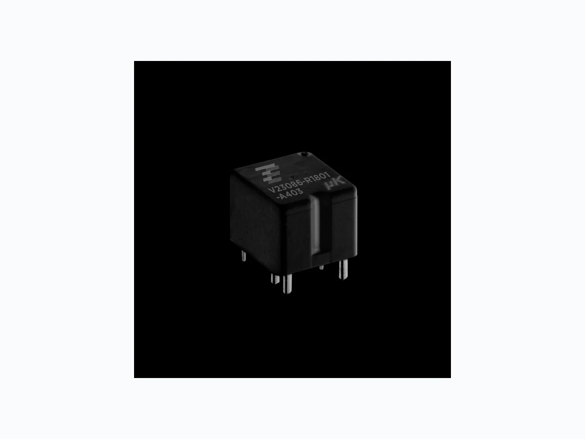
Product code Version Design Coil Contact Cont. material Arrangement Part number V23086-C1021-A502 PCB THT, Single Standard Single AgSnO2 1 form A, 1 NO (lamp) 8-1416000-7 V23086-C1001-A403 cleanable 1 form C, 1 CO (standard) 0-1393280-6 V23086-C1002-A803 Sensitive 1 form C, 1 CO (standard) 2-1414987-3 V23086-R1801-A403 PCB THR, Standard 1 form C, 1 CO (standard) 6-1414920-0 V23086-R1802-A803 vented Sensitive 1 form C, 1 CO (wiper) 7-1414967-8 V23086-R1821-A502 Standard 1 form A, 1 NO (lamp) 6-1414918-8 This list represents the most common types and does not show all variants covered by this datasheet. Other types on request.