

 Download PDF
DATASHEET SEARCH SITE
Document overview
- Manufacturer or author: Provided By digicamel.com
- PDF pages: 2
Technical content
Features
- Small size for high density PC board mounting.
- 1 Form A contact arrangements.
- Creepage spacings of 6.5mm between contact and coil.
- Ideal for appliance, office equipment.
- 4,000VAC dielectric strength between contact and coil.
- UL Class F (155°C) approved insulation system. File E29244 File LR48471 Coil Data @ 20°C T77 series
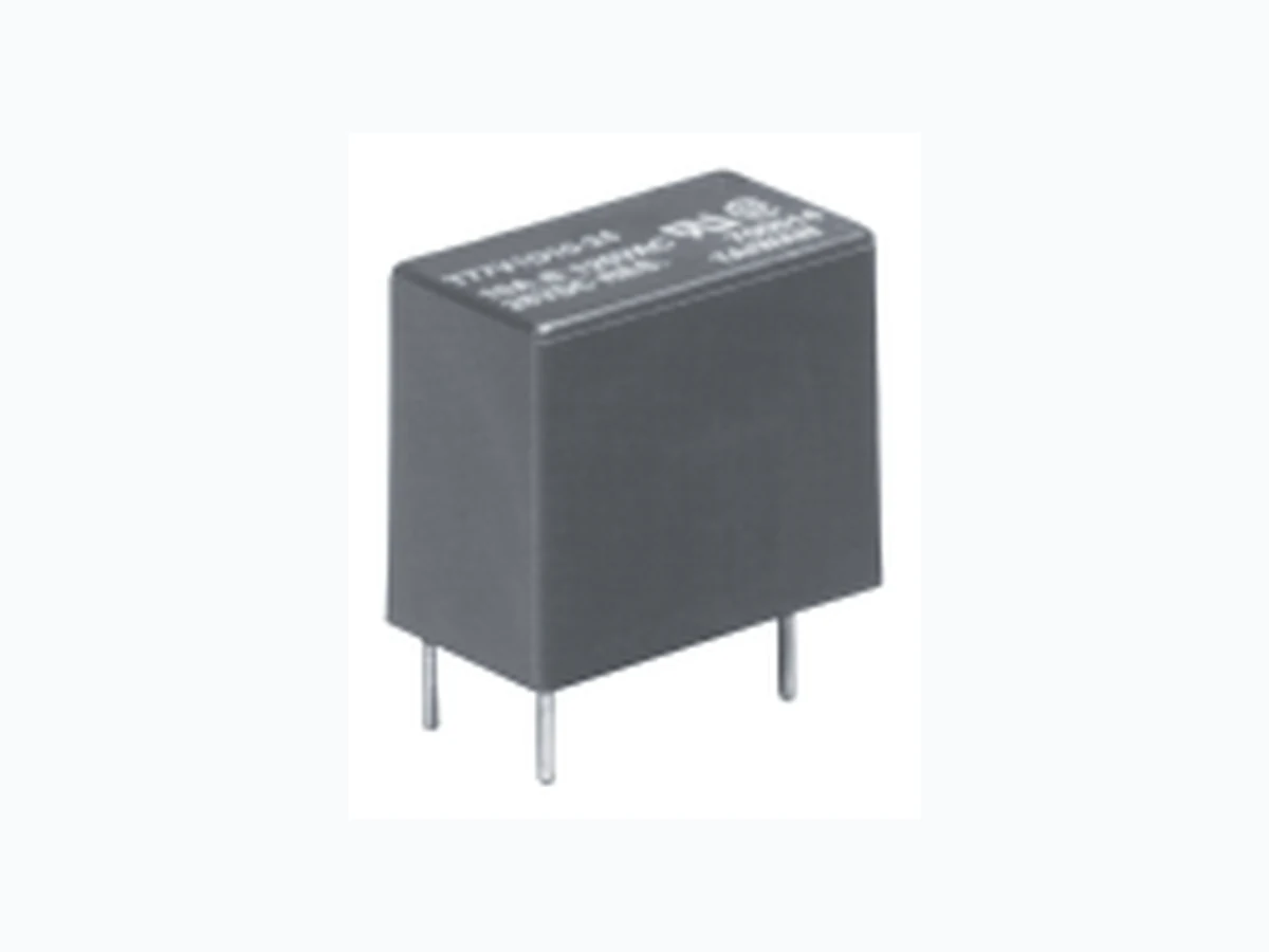
10 Amp Miniature
Initial Insulation Resistance Between Mutually Insulated Elements: 108 ohms, min. @ 500VDC. Initial Dielectric Strength Between Open Contacts: 750VAC 50/60 Hz. (1 minute). Between Coil and Contacts: 4,000VAC 50/60 Hz. (1 minute). Rated Coil Must Must Coil Resistance Operate Release Voltage (Ohms) ±10% Voltage Voltage (VDC) Contact Rating 3 Contact Rating 10 (VDC) (VDC) 3 45 20 2.25 0.15 5 125 55 3.75 0.25 12 720 320 9.00 0.60 24 2,800 1,280 18.00 1.20 Mechanical Data Termination: Printed circuit board. Enclosures (94V-0 Flammability Ratings): T77S: Immersion cleanable. T77V: Vented, flux-tight, plastic cover. Weight: 0.36 oz. (9g). Environmental Data Temperature Range: Storage: -40°C to +130°C. Operating: Contact Rating 3: -40°C to +105°C. Contact Rating 10: -40°C to +85°C. Vibration: Mechanical: 10 to 55 Hz., 1.5mm double amplitude. Operational: 10 to 55 Hz., 1.5mm double amplitude. Shock: Mechanical: 100g min. Operational: 10g min. Operating Humidity: 45 to 85% RH. Operate Data @ 20°C Operate Time: 10 ms, max. (excluding bounce). Release Time: 4 ms, max. (excluding bounce). Contact Data @ 20°C Arrangements: 1 Form A (SPST-NO). Material: Contact rating 3 - Silver. Contact rating 10 - Silver alloy. Max. Switching Rate: 300 ops./min. (no load). 30 ops./min. (rated load). Expected Mechanical Life: 10 million operations. Expected Electrical Life: 100,000 operations. Minimum Contact Load: 10mA @ 5VDC. Initial Contact Resistance: 100 milliohms max. @ 100mA, 6VDC. *Denotes test at 70 °C ambient temperature. Denotes test at 85 °C ambient temperature. *Denotes test at 105 °C ambient temperature. Contact Ratings @ 20°C with relay properly vented. Remove vent nib after soldering and cleaning. Contact UL/CSA Ratings Type Operations Rating 3 3A @ 277VAC Resistive 6,000 10LRA/1.5FLA @ 120VAC Motor 30,000 5.4LRA/0.9FLA @ 240VAC Motor 30,000 3LRA/1.5FLA @ 120VAC Motor 100,000* 3A @ 250VAC Resistive 100,000 3A @ 250VAC UL General Purpose 100,000 3A @ 30VDC Resistive 100,000 2A @ 120VAC Gen. Purpose 100,000* 3A @ 120VAC Resistive 100,000* 10 10LRA/1.5FLA @ 120VAC Motor 30,000 5.4LRA/0.9FLA @ 240VAC Motor 30,000 10A @ 250VAC Resistive 100,000 10A @ 30VDC Resistive 100,000 10A @ 250VAC UL General Purpose 200,000 Users should thoroughly review the technical data before selecting a product part number. It is recommended that user also seek out the pertinent approvals files of the agencies/laboratories and review them to ensure the product meets the requirements for a given application. ZV
10-2011, Rev. 1011 www.te.com © 2011 Tyco Electronics Corporation, a TE Connectivity Ltd. company Datasheets and product specification according to IEC 61810-1 and to be used only together with the ‘Definitions’ section. Datasheets and product data is subject to the terms of the disclaimer and all chapters of the ‘Definitions’ section, available at http://relays.te.com/definitions Datasheets, product data, ‘Definitions’ sec- tion, application notes and all specifications are subject to change. Potter & Brumfield General Purpose Relays PCB Relays Miniature PCB Relay T77 (Continued) Insulation Data Initial dielectric strength between open contacts 750Vrms between contact and coil 4000Vrms Clearance/creepage between contact and coil >3.2/6.4mm Other Data Material compliance: EU RoHS/ELV, China RoHS, REACH, Halogen content refer to the Product Compliance Support Center at www.te.com/customersupport/rohssupportcenter Ambient temperature 3A type: -30°C to +105°C 5A and 10A type: -30°C to +85°C Category of environmental protection IEC 61810 RTII - dust protected RTIII - wash tight Shock resistance (functional) 10g Shock resistance (destructive) 100g Weight 9g Resistance to soldering heat THT IEC 60068-2-20 RTII: 270°C/10s RTIII: 260°C/5s Packaging/unit Tray/100, carton box/1000 Dimensions PCB layout Bottom view on solder pins 421 Dimensions are shown for reference purposes only. Dimensions are in inches over (millimeters) unless otherwise specified. Specifications and availability subject to change. www.tycoelectronics.com Technical support: Refer to inside back cover. P&B Catalog 1308242 Issued 3-03 (PDF Rev. 11-04) Outline Dimensions Wiring Diagram (Bottom View)
1 Form A
Suggested PC Board Layout (Bottom View) .716 (18.20) .57 (14.70) .40 (10.20)
2 PLACES
.017 X .017 (.45 X .45) .04 X .011 (1.0 X .30) .16 (4.0) *Not suitable for immersion cleaning processes. Our authorized distributors are more likely to maintain the following items in stock for immediate delivery. T77V1D3-12 T77V1D3-24 T77V1D10-12 T77V1D10-24 T77S1D3-12 T77S1D3-24 T77S1D10-12 T77S1D10-24 .100 (2.54).50 (12.7) .30 (7.6) 4 - .051(1.3)Ø Coil Power (W)Coil Power (W) Time (msec) T emp. Rise (Deg.) Release Time Operate Time 100 Contact Current (A) Operation (x 104) 0 1 2 3 45 67 8 9 10 Contact Rating 10, 120VAC Res. Contact Rating 3, 250VAC Res. Figure 1 - Coil Temperature Rise Operate Time Life Expectancy Note: Graphical data should not be used as a substitute for specific application verification. To be used for estimates only.
Ordering Information
Typical Part Number B T77 V 1 D 10 -24 1. Basic Series: T77 = Miniature PCB relay. 2. Enclosure: V = Vented (Flux-tight)* S = Immersion cleanable case 3. Contact Arrangement: 1 = (SPST-NO) 4. Coil Input: D = DC Voltage 5. Contact Rating: 3 = 3A 10 = 10A 6. Coil Voltage: 03 = 3VDC 05 = 5VDC 12 = 12VDC 24 = 24VDC 421 Dimensions are shown for reference purposes only. Dimensions are in inches over (millimeters) unless otherwise specified. Specifications and availability subject to change. www.tycoelectronics.com Technical support: Refer to inside back cover. P&B Catalog 1308242 Issued 3-03 (PDF Rev. 11-04) Outline Dimensions Wiring Diagram (Bottom View) Suggested PC Board Layout (Bottom View) .716 (18.20) .57 (14.70) .40 (10.20) .017 X .017 (.45 X .45) .04 X .011 (1.0 X .30) .16 (4.0) *Not suitable for immersion cleaning processes. Our authorized distributors are more likely to maintain the following items in stock for immediate delivery. T77V1D3-12 T77V1D3-24 T77V1D10-12 T77V1D10-24 T77S1D3-12 T77S1D3-24 T77S1D10-12 T77S1D10-24 .100 (2.54).50 (12.7) .30 (7.6) 4 - .051(1.3)Ø Coil Power (W)Coil Power (W) Time (msec) T emp. Rise (Deg.) Release Time Operate Time 100 Contact Current (A) Operation (x 104) 0 1 2 3 45 67 8 9 10 Contact Rating 10, 120VAC Res. Contact Rating 3, 250VAC Res. Figure 1 - Coil Temperature Rise Operate Time Life Expectancy Note: Graphical data should not be used as a substitute for specific application verification. To be used for estimates only. Typical Part Number B T77 V 1 D 10 -24 1. Basic Series: T77 = Miniature PCB relay. 2. Enclosure: V = Vented (Flux-tight)* S = Immersion cleanable case 3. Contact Arrangement: 1 = (SPST-NO) 4. Coil Input: D = DC Voltage 5. Contact Rating: 3 = 3A 10 = 10A 6. Coil Voltage: 03 = 3VDC 05 = 5VDC 12 = 12VDC 24 = 24VDC Terminal assignment Bottom view on solder pins 421 Dimensions are shown for reference purposes only. Dimensions are in inches over (millimeters) unless otherwise specified. Specifications and availability subject to change. www.tycoelectronics.com Technical support: Refer to inside back cover. P&B Catalog 1308242 Issued 3-03 (PDF Rev. 11-04) Outline Dimensions Wiring Diagram (Bottom View) Suggested PC Board Layout (Bottom View) .716 (18.20) .57 (14.70) .40 (10.20) .017 X .017 (.45 X .45) .04 X .011 (1.0 X .30) .16 (4.0) *Not suitable for immersion cleaning processes. Our authorized distributors are more likely to maintain the following items in stock for immediate delivery. T77V1D3-12 T77V1D3-24 T77V1D10-12 T77V1D10-24 T77S1D3-12 T77S1D3-24 T77S1D10-12 T77S1D10-24 .100 (2.54).50 (12.7) .30 (7.6) 4 - .051(1.3)Ø Coil Power (W)Coil Power (W) Time (msec) T emp. Rise (Deg.) Release Time Operate Time 100 Contact Current (A) Operation (x 104) 0 1 2 3 45 67 8 9 10 Contact Rating 10, 120VAC Res. Contact Rating 3, 250VAC Res. Figure 1 - Coil Temperature Rise Operate Time Life Expectancy Note: Graphical data should not be used as a substitute for specific application verification. To be used for estimates only. Typical Part Number B T77 V 1 D 10 -24 1. Basic Series: T77 = Miniature PCB relay. 2. Enclosure: V = Vented (Flux-tight)* S = Immersion cleanable case 3. Contact Arrangement: 1 = (SPST-NO) 4. Coil Input: D = DC Voltage 5. Contact Rating: 3 = 3A 10 = 10A 6. Coil Voltage: 03 = 3VDC 05 = 5VDC 12 = 12VDC 24 = 24VDC Product code structure Typical product code T77 V 1 D 10 -12 Type T77 Miniature PCB Relay T77 Category of protection V Flux proof S Wash tight Contact arrangement 1 1 Form A, 1NO Coil input D DC coil Contact rating and coil power 450 mWcoil power 200mW coil power 5 5A type, coil power 450mW 3 3A type, coil power 200mW 10 10A type, coil power 450mW Coil voltage Coil code: please refer to coil versions table (e.g. 12 = 12VDC) Insulation system Blank UL Class 155 (F) A UL Class 120 (E) Special types Blank Standard Product code Enclosure Contact rating Cont.material Coil voltage Coil power Part number T77S1D3-05 Wash tight 3A Ag 5VDC 200mW 1-1393194-3 T77V1D3-12 Flux proof 3A Ag 12VDC 200mW 2-1393194-6 T77S1D3-12 Wash tight 3A Ag 12VDC 200mW 1-1393194-5 T77V1D3-24 Flux proof 3A Ag 24VDC 200mW 2-1393194-7 T77S1D3-24 Wash tight 3A Ag 24VDC 200mW 1-1393194-6 T77V1D10-05 Flux proof 10A AgCdO 5VDC 450mW 1-1393194-8 T77S1D10-05 Wash tight 10A AgCdO 5VDC 450mW 1393194-7 T77V1D10-09 Flux proof 10A AgCdO 9VDC 450mW 1440005-1 T77S1D10-03 Wash tight 10A AgCdO 3VDC 450mW 1393194-6 T77V1D10-12 Flux proof 10A AgCdO 12VDC 450mW 1-1393194-9 T77S1D10-12 Wash tight 10A AgCdO 12VDC 450mW 1393194-9 T77V1D10-24 Flux proof 10A AgCdO 24VDC 450mW 2-1393194-1 T77S1D10-24 Wash tight 10A AgCdO 24VDC 450mW 1-1393194-0