
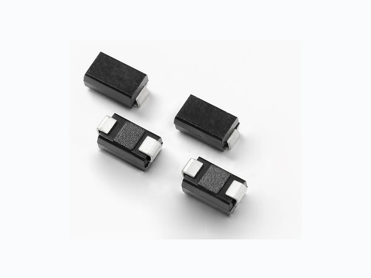
1SMA5.0AT3G LITTELFUSE
Document overview
- Manufacturer or author: Provided By digicamel.com
- PDF pages: 5
Technical content
Features
The 1SMA5.0AT3G series is designed to protect voltage sensitive components from high voltage, high energy transients. They have excellent clamping capability, high surge capability, low zener impedance and fast response time. The 1SMA5.0AT3G series is supplied in the Littelfuse exclusive, cost-effective, highly reliable package and is ideally suited for use in communication systems, automotive, numerical controls, process controls, medical equipment, business machines, power supplies and many other industrial/consumer applications.
Description
Parameter Symbol Value Unit Peak Power Dissipation (Note 1) @ TL = 25°C, Pulse Width = 1 ms PPK 400 W DC Power Dissipation @ TL = 75°C Measured Zero Lead Length (Note 2) Derate Above 75°C Thermal Resistance from Junction to−Lead PD R JL 1.0 W mW/°C °C/W DC Power Dissipation (Note 3) @ TA = 25°C Derate Above 25°C Thermal Resistance from Junction–to– Ambient PD R0JA 0.5 4.0 250 W mW/°C °C/W Forward Surge Current (Note 4) @ TA = 25°C IFSM 40 A Operating and Storage Temperature Range TJ, Tstg -65 to +150 °C Maximum Ratings and Thermal Characteristics 1SMA5.0AT3G Series Functional Diagram Bi-directional Uni-directional Cathode Anode Pb Stresses exceeding those listed in the Maximum Ratings table may damage the device. If any of these limits are exceeded, device functionality should not be assumed, damage may occur and reliability may be affected. 1 . 10 X 1000 µs, non−repetitive. 2. 1” square copper pad, FR−4 board. 3. FR−4 board, using Littelfuse minimum recommended footprint, as shown in 403D-02 case outline dimensions spec. 4. 1/2 sine wave (or equivalent square wave), PW = 8.3 ms, duty cycle = 4 pulses per minute maximum. Additional Information Samples Resources Datasheet
© 2017 Littelfuse, Inc. Specifications are subject to change without notice. Revised: 09/14/17 TVS Diodes Surface Mount > 400W > 1SMA5.0AT3G Series Symbol Parameter IPP Maximum Reverse Peak Pulse Current VC Clamping Voltage @ IPP VRWM Working Peak Reverse Voltage IR Maximum Reverse Leakage Current @ VRWM VBR Breakdown Voltage @ IT IT Test Current IF Maximum Temperature Coefficient of VBR VF Forward Voltage @ IF 5. 1/2 sine wave or equivalent, PW = 8.3 ms non−repetitive duty cycle IPP IF V I IRIT VRWMVC VBR VF I-V Curve Characteristics (TA = 25°C unless otherwise noted, VF = 3.5 V Max. @ IF = 30 A for all types) (Note 5) 5. 1/2 sine wave or equivalent, PW = 8.3 ms, non−repetitive duty cycle.
© 2017 Littelfuse, Inc. Specifications are subject to change without notice. Revised: 09/14/17 TVS Diodes Surface Mount > 400W > 1SMA5.0AT3G Series
Electrical Characteristics
Breakdown Voltage VC @ IPP (Note 8) Device* Device Marking V RWM (Note 6) IR @ VRWM VBR @ IT (V) (Note 7) @ IT VC IPP C Typ. (Note 9) Volts µA MIN NOM MAX mA Volts Amps pF 6. A transient suppressor is normally selected according to the working peak reverse voltage (VRWM), which should be equal to or greater than the DC or continuous peak operating voltage level. 7. V BR measured at pulse test current IT at an ambient temperature of 25°C. 8. Surge current waveform per Figure 2 and derate per Figure 3. 9. Bias voltage = 0 V , F = 1 .0 MHz, TJ = 25°C. †Please see 1SMA10CAT3 to 1SMA75CAT3 for Bidirectional devices.
© 2017 Littelfuse, Inc. Specifications are subject to change without notice. Revised: 09/14/17 TVS Diodes Surface Mount > 400W > 1SMA5.0AT3G Series Dimensions Part Marking System NOTES: 1 . DIMENSIONING AND TOLERANCING PER ANSI Y14.5M, 1982. 2. CONTROLLING DIMENSION: INCH. 3. DIMENSION b SHALL BE MEASURED WITHIN DIMENSION L. STYLE 1: PIN 1 . CATHODE (POLARITY BAND) 2. ANODE Soldering Footrpint Physical Specifications Case Void-free, transfer-molded, thermosetting plastic Polarity Cathode indicated by molded polarity notch Mounting Position Any Finish All external surfaces are corrosion resistant and leads are readily solderable
ORDERING INFORMATION
Device Package Shipping† 1SMAxxAT3G SMA (Pb−Free) 5,000 / Tape & Reel Dim Inches Millimeters Min Nom Max Min Nom Max E bD L c A POLARITY INDICATOR OPTIONAL AS NEEDED (SEE STYLES) HE 4.000 0.157 2.000 0.079 2.000 0.079 mm inchesSCALE 8:1 Flow/Wave Soldering (Solder Dipping) Peak T emperature : 260OC Dipping Time : 10 seconds D xx AY WW xx = Device Code (Refer to page 3) A= Assembly Location Y= Year WW = Work Week Disclaimer Notice - Information furnished is believed to be accurate and reliable. However, users should independently evaluate the suitability of and test each product selected for their own applications. Littelfuse products are not designed for, and may not be used in, all applications. Read complete Disclaimer Notice at: www.littelfuse.com/disclaimer-electronics.