
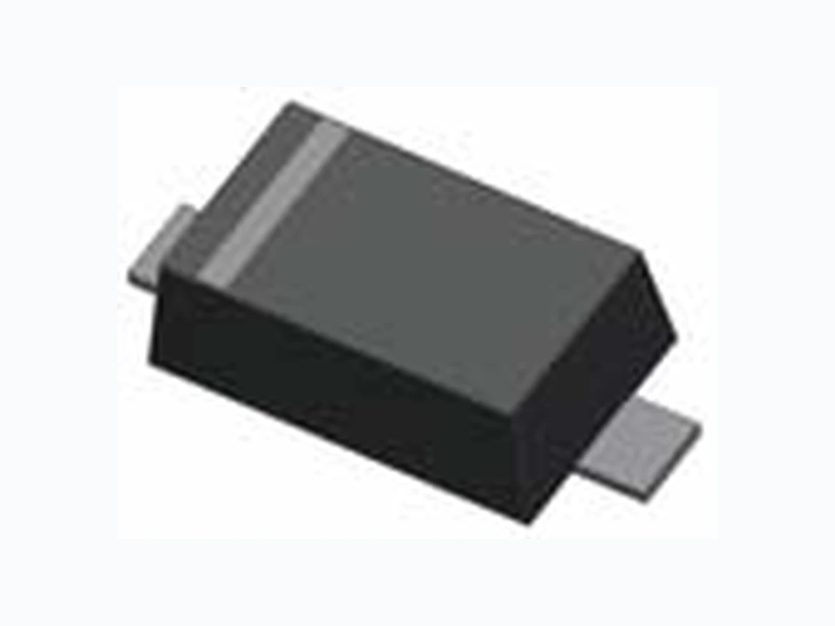
1N914BW TSC
Document overview
- Manufacturer or author: Provided By digicamel.com
- PDF pages: 2
Technical content
Features
Terminal: Matte tin plated, lead free., solderable per MIL-STD-202, Method 208 guaranteed Unit (mm) Unit (inch) Dimensions A B C Green compound (Halogen free) with suffix "G" on packing code and prefix "G" on date code ValueSymbol High temperature soldering guaranteed: 260°C/10s
Ordering Information
Part No. Packing 1NxxxxW RH Non-Repetitive Peak Reverse Voltage V RSM D E F 400 100 Reverse Leakage Current Reverse Breakdown Voltage VF IR V(BR) CJ 0.62 μA Units V V Min Max ns 1.0 1.0 4.0 nA pF4.0 5.0 Type Number Symbol 100 0.72 Trr V V mA mA °C-65 to + 150 300 150 °C/W450 V RRM Junction and Storage Temperature Range Mean Forward Current IFRM IO TJ, TSTG RθJA Repetitive Peak Forward Current Repetitive Peak Reverse Voltage Thermal Resistance (Junction to Ambient) (Note 1) mW Polarity : Indicated by cathode band Weight : 8.85±0.5 mg Rating at 25°C ambient temperature unless otherwise specified. Type Number Units PDPower Dissipation 3Kpcs / 7" Reel D A B C E F Version : C09
400mW High Speed SMD Switching Diode Small Signal Diode Rating and Sharacteristic Curves FIG 3 Admissible Power Dissipation Curve 100 200 300 400 500 0 20 40 60 80 100 120 140 160 Power Dissipation (mW) FIG 4 Typical Junction Capacitance 02468 1 0 Junction Capacitance (pF) Ambient Temperature (°C) Reverse Voltage (V) FIG 1 Typical Forward Characteristics 0.001 0.01 0.1 100 Instantaneous Forward Volatge (V) Instantaneous Forward Current (A) Ta=25°C FIG 2 Reverse Current vs Reverse Voltage 0.01 0.1 100 0 20 40 60 80 100 120 Reverse Volatge (V) Reverse Current (uA) Ta=25°C FIG 5 Forward Resistance vs. Forward Current 100 1000 10000 0 0 1 10 100 Forward Current (mA) Dynamic Forward Resistance (Ώ) Version : C09