

 Download PDF
1N5817W_V01 YFWDIODE
Document overview
- Manufacturer or author: Provided By digicamel.com
- PDF pages: 3
Technical content
1N5817W THRU 1N5819W SOD123FL 1 / 3 www.yfwdiode.com Dongguan YFW Electronics Co, Ltd. SCHOTTKY BARRIER RECTIFIERS Reverse Voltage - 20 to 40 V Forward Current - 1 A
FEATURES
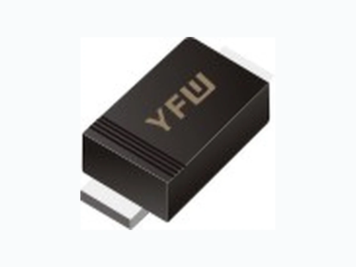
Metal silicon junction, majority carrier conduction Guarding for overvoltage protection Low power loss, high efficiency High current capability low forward voltage drop High surge capability For use in low voltage, high frequency inverters, free wheeling, and polarity protection applications Lead free in comply with EU RoHS 2011/65/EU directives MECHANICAL DATA Case: SOD-123FL Terminals: Solderable per MIL-STD-750, Method 2026 Approx. Weight: 15mg / 0.000 48oz Pinning 1.Cathode 2.Anode 1 2 SOD123FL Maximum Ratings and Electrical characteristics Ratings at 25 °C ambient temperature unless otherwise specified. Parameter Symbols 1N5817W 1N5818W 1N5819W Units Maximum Repetitive Peak Reverse Voltage VRRM 20 30 40 V Maximum RMS voltage VRMS 14 21 28 V Maximum DC Blocking Voltage VDC 20 30 40 V Maximum Average Forward Rectified Current IF(AV) 1 A Peak Forward Surge Current, 8.3ms Single Half Sine-wave Superimposed On Rated Load (JEDEC method) IFSM 25 A Maximum Instantaneous Forward Voltage at 1 A at 3 A VF 0.45 0.75 0.55 0.875 0.6 0.9 V Maximum Instantaneous Reverse Current at Rated DC Reverse Voltage TA = 25°C TA = 100°C IR 1 10 mA Typical Junction Capacitance Cj 110 pF Storage and Operating Junction Temperature Range Tj, Tstg -55 ~ +150 °C Marking Code 1N5817W SJ 1N5818W SK 1N5819W SL
1N5817W THRU 1N5819W SOD123FL 2 / 3 www.yfwdiode.com Dongguan YFW Electronics Co, Ltd. 10 100 Fig.5 Maximum Non-Repetitive Peak Forward Surage Current Peak A)Forward Surage Current ( Number of Cycles at 50Hz 8.3 ms Single Half Sine Wave (JEDEC Method) 0.1 0 0.4 0.5 0.7 Fig.3 Typical Forward Characteristic Instaneous Forward Current (A) Instaneous Forward Voltage (V) 0.1 1.0 T =25 J T =125 J 0.2 0.5 0.3 0.60.2 Fig.2 Typical Reverse Characteristics Instaneous Current ( μA)Reverse 20 40 60 800 T =25J °C T =75J °C T =125J °C Percent of Rated Peak Reverse Voltage(%) 100 100 101 102 103 104 Fig.4 Typical Junction Capacitance 0.1 Junction Capacitance ( pF) Reverse Voltage (V) 100 200 500 1001 Fig.1 Forward Current Derating Curve 0.2 0.4 0.6 0.8 1.0 1.2 0.0 25 50 75 100 125 150 Average Forward Current (A) Single phase half-wave 60 Hz resistive or inductive load Case Temperature (°C)
1N5817W THRU 1N5819W SOD123FL 3 / 3 www.yfwdiode.com Dongguan YFW Electronics Co, Ltd. Package Outline Plastic surface mounted package; 2leads SOD-123FL The recommended mounting pad size Summary of Packing Options Package Packing Description Packing Quantity Industry Standard Tape/Reel,13”reel 10000 EIA-481-1 SOD-123FL Tape/Reel,7”reel 3000 EIA-481-1 A A C ∠ALL ROUND V AM e UNIT mm max min mil max min 7.9 4.7 114 102 150 138 A C D E HE ∠ 1.1 0.8 e Bottom View HE ∠ALL ROUND E D E g pad pad Top View 0.9 0.7 g g 2.0 (79) 1.2 (47) mm (mil)Unit: 1.2 (47) 1.2 (47)