

 Download PDF
DATASHEET SEARCH SITE
Document overview
- Manufacturer or author: Provided By digicamel.com
- PDF pages: 5
Technical content
T4-LDS-0231, Rev. 1 (111902) ©2011 Microsemi Corporation Page 1 of 5 1N5415 thru 1N5420 Available on commercial versions VOIDLESS HERMETICALLY SEALED FAST RECOVERY GLASS RECTIFIERS Qualified per MIL-PRF-19500/411 Qualified Levels: JAN, JANTX, JANTXV and JANS
DESCRIPTION
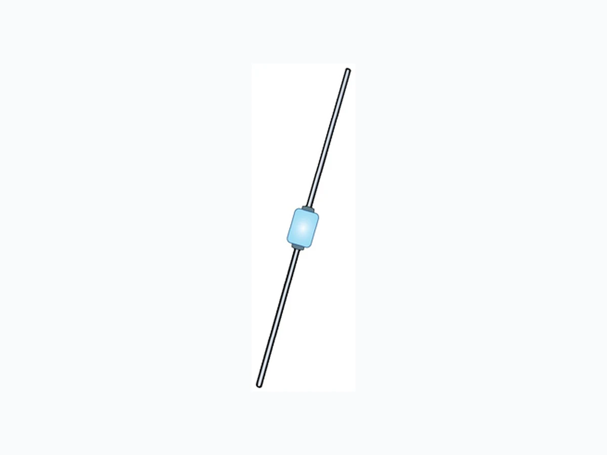
This “fast recovery” rectifier diode series is military qualified and is ideal for high-reliability applications where a failure cannot be tolerated. These industry-recognized 3.0 amp rated rectifiers for working peak reverse voltages from 50 to 600 volts are hermetically sealed with voidless-glass construction using an internal “Category 1” metallurgical bond. These devices are also available in surface mount MELF package configurations. Microsemi also offers numerous other rectifier products to meet higher and lower current ratings with various recovery time speed requirements including fast and ultrafast device types in both through-hole and surface mount packages. “B” Package Also available in: “B” SQ-MELF (D-5B) Package (surface mount) 1N5415US – 1N5420US Important: For the latest information, visit our website http://www.microsemi.com.
FEATURES
- Popular JEDEC registered 1N5415 thru 1N5420 series.
- Voidless hermetically sealed glass package.
- Quadruple-layer passivation.
- Internal “Category 1” metallurgical bonds.
- Working Peak Reverse Voltage 50 to 600 volts.
- JAN, JANTX, JANTXV and JANS qualifications available per MIL-PRF-19500/411.
- RoHS compliant versions available (commercial grade only). APPLICATIONS / BENEFITS
- Fast recovery 3 amp 50 to 600 volt rectifiers.
- Military and other high-reliability applications.
- General rectifier applications including bridges, half-bridges, catch diodes, etc.
- High forward surge current capability.
- Extremely robust construction.
- Low thermal resistance.
- Controlled avalanche with peak reverse power capability.
- Inherently radiation hard as described in Microsemi “MicroNote 050”. MAXIMUM RATINGS MSC – Lawrence
6 Lake Street,
Lawrence, MA 01841 Tel: 1-800-446-1158 or (978) 620-2600 Fax: (978) 689-0803 MSC – Ireland Gort Road Business Park, Ennis, Co. Clare, Ireland Tel: +353 (0) 65 6840044 Fax: +353 (0) 65 6822298 Website: www.microsemi.com Parameters/Test Conditions Symbol Value Unit Junction and Storage Temperature TJ and TSTG -65 to +175 oC Thermal Resistance Junction-to-Lead (1) RӨJL 22 oC/W Forward Surge Current @ 8.3 ms half-sine IFSM 80 A Average Rectified Forward Current (4) @ TA = +55 oC @ TA = +100 oC IO (2, 3) IO (3) A Working Peak Reverse Voltage 1N5415 1N5416 1N5417 1N5418 1N5419 1N5420 VRWM 50 100 200 400 500 600 V Maximum Reverse Recovery Time (5) 1N5415 1N5416 1N5417 1N5418 1N5419 1N5420 trr 150 150 150 150 250 400 ns Solder Temperature @ 10 s TSP 260 oC See notes on next page.
T4-LDS-0231, Rev. 1 (111902) ©2011 Microsemi Corporation Page 2 of 5 1N5415 thru 1N5420 MAXIMUM RATINGS Notes: 1. At 3/8 inch (10 mm) lead length from body . 2. Derate linearly at 22 mA/oC for 55 oC < TA < 100 oC. 3. Above TA = 100 oC, derate linearly at 26.7 mA/oC to zero at T A = 175 oC. 4. These ambient ratings are for PC boards where thermal resistance from mounting point to ambient is sufficiently controlled wh ere TJ( max) does not exceed 175 oC. 5. IF = 0.5 A, IRM = 1 A, IR(REC) = 0.250 A. MECHANICAL and PACKAGING
- CASE: Hermetically sealed voidless hard glass with tungsten slugs.
- TERMINALS: Axial-leads are tin/lead (Sn/Pb) over copper. RoHS compliant matte-tin is available for commercial grade only.
- MARKING: Body paint and part number.
- POLARITY: Cathode band.
- TAPE & REEL option: Standard per EIA-296. Contact factory for quantities.
- WEIGHT: 750 milligrams.
- See Package Dimensions on last page. PART NOMENCLATURE JAN 1N5415 (e3) Reliability Level JAN = JAN Level JANTX = JANTX Level JANTXV = JANTXV Level JANS = JANS Level Blank = commercial JEDEC type number See Electrical Characteristics table RoHS Compliance e3 = RoHS compliant (available on commercial grade only) Blank = non-RoHS compliant SYMBOLS & DEFINITIONS Symbol Definition VBR Minimum Breakdown Voltage: The minimum voltage the device will exhibit at a specified current. VRWM Working Peak Reverse Voltage: The maximum peak voltage that can be applied over the operating temperature range excluding all transient voltages (ref JESD282-B). IO Average Rectified Output Current: The Output Current averaged over a full cycle with a 50 Hz or 60 Hz sine-wave input and a 180 degree conduction angle. VF Maximum Forward Voltage: The maximum forward voltage the device will exhibit at a specified current. IR Maximum Reverse Current: The maximum reverse (leakage) current that will flow at the specified voltage and temperature. trr Reverse Recovery Time: The time interval between the instant the current passes through zero when changing from the forward direction to the reverse direction and a specified decay point after a peak reverse current occurs.
T4-LDS-0231, Rev. 1 (111902) ©2011 Microsemi Corporation Page 3 of 5 1N5415 thru 1N5420
ELECTRICAL CHARACTERISTICS
VBR @ 50 µA Volts FORWARD VOLTAGE VF @ 9 A MAXIMUM REVERSE CURRENT IR @ VRWM CAPACITANCE C VR @ 4 V pF MIN. Volts MAX. Volts 25 oC µA 100 oC µA 1N5415 1N5416 1N5417 1N5418 1N5419 1N5420 110 220 440 550 660 0.6 0.6 0.6 0.6 0.6 0.6 1.5 1.5 1.5 1.5 1.5 1.5 1.0 1.0 1.0 1.0 1.0 1.0 550 430 250 165 140 120 NOTE 1: IF = 0.5 A, IRM = 1 A, IR(REC) = 0.250 A.
T4-LDS-0231, Rev. 1 (111902) ©2011 Microsemi Corporation Page 5 of 5 1N5415 thru 1N5420 PACKAGE DIMENSIONS Symbol Dimensions Notes Inch Millimeters Min Max Min Max BD 0.110 0.180 2.79 4.57 3 LD 0.036 0.042 0.91 1.07 4 BL 0.130 0.260 3.30 6.60 4 LL 0.90 1.30 22.9 33.0 NOTES: 1. Dimensions are in inches. 2. Millimeter equivalents are given for general information only. 3. Dimension BD shall be measured at the largest diameter. 4. The BL dimension shall include the entire body including slugs and sections of the lead over which the diameter is uncontrolled. This uncontrolled area is defined as the zone between the edge of the diode body and extending .050 inch (1.27 mm) onto the leads. 5. In accordance with ASME Y14.5M, diameters are equivalent to Φx symbology.