
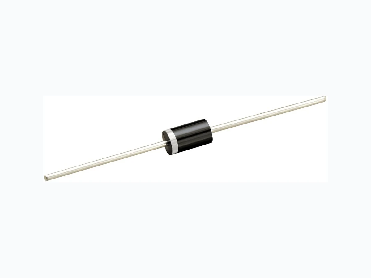
1N5400GV RECTRON
Document overview
- Manufacturer or author: Provided By digicamel.com
- PDF pages: 5
Technical content
MAXIMUM RATINGS AND ELECTRICAL CHARACTERISTICS Ratings at 25 o C ambient temperature unless otherwise specified. Single phase, half wave, 60 Hz, resistive or inductive load. For cap acitive load, der ate current by 20%. 1N5400GV THRU 1N5408GV MAXIMUM RATINGS (@ T A =25 O C unless otherwise noted)
ELECTRICAL CHARACTERISTICS
(@T A =25 O C unless otherwise noted) RATINGS Maximum Recurrent Peak Reverse Voltage Maximum RMS Voltage Maximum DC Blocking Voltage Maximum Average Forward Rectified Current at T L = 105 o C Peak Forward Sur ge Cur rent 8.3 ms single half sine-wave superimposed on rated load (JEDEC method) Typical The rmalResistance(Note2) TypicalJunctionCapacitance(Note1) SYMBOL V RRM V DC I FSM C J T J STG V RMS UNITS Volts Volts Amps3.0 200 5.0 Amps C/W C Operating and Storage Temperature Range R QJL R QJA I O -55 to + 150 pF Volts 100 600 200 1N5400G 1N5402G 1N5406G1N5401G 1N5404G 40050 100 600 200 40050 70 420 140 280 1000 1N5408G 1000 70035 800 1N5407G 1N5400G 1N5402G 1N5406G1N5401G 1N5404G 1N5408G 1N5407G 800 560 NOTES : 1. Mea sured at 1 MHz and applied reverse voltage of 4.0 volts. 2. Typ ical Thermal Resistance : At 9.5mm lead lengths,PCB mounted. CHARACTERISTICS at Rated DC Blocking Voltage V F SYMBOL I R uAmpsMaximum DC Rev erse Current Maximum Instantaneous Forward Voltage at 3.0A DC Volts 0.5 A =150 o C A =2 5 o C .98 UNITS
FEATURES
- Low cost * Low leakage * Low for ward voltage drop * High current capability MECHANICAL DATA * Case: Molded plastic * Epoxy: Device has UL flammability classification 94V-O * Lead: MIL-STD-202E method 208C guaranteed * Mounting position: Any * Weight:1.2 grams GLASS PASSIVATED RECTIFIER VOLTAGE RANGE 50 to 1000 Volts CURRENT 3.0 Amperes Dimensions in inches and (millimeters) MIN. .335 (8.5) .375 (9.5) MIN. .220 (5.6) .197 (5. 0) DIA. .052 (1. 3) .048 (1.2) DIA. DO-201AD I T A S166 Typical Current Squared Time * P/N suffix V means Halogen-free P/N suffix V means AEC-Q101 qualified, e.g:1N5400G V mAmps .954 (24) .954 (24) 2020-11 REV:O
LEAD TEMPERATURE, ( O TNATSNIA U OENS E RV E SRE (uA) ,TNERRUC 5.0 4.0 3.0 2.0 1.0 7550 175 100 125 150 FIG.1 TYPICAL FORWARD CURRENT DERATING CURVE PERCENT OF RATED PEAK REVERSE VOLTAGE, (%) )A(,TNERRUCDRAWROFEGAREVA 1.0 0.1 1000 10000 6020 40 80 100 120 140 FIG.2 REVERSE CHARACTERISTICS Single Phase Half Wave 60Hz Resistive or Inductive Load T A =2 5 O C T A =150 O C NUMBER OF CYCLES AT 60Hz FPKAER O) A(,TNERRUCEGRUSDRAW INSTANTANEOUS FORWARD VOLTAGE, (V) 110 100 200 IE NOASNT T NAU S E RNFO R AWRD U CR T A (,) 1.0 0.3 0.1 0.03 0.01 3.0 FIG.3 INSTANTANEOUS FORWARD CHARACTERISTICS FIG.4 MAXIMUM NON-REPETITIVE FORWARD SURGE CURRENT REVERSE VOLTAGE, (V) NTUJC I O N P ACACI C TAN , EF p)( 200 100 FIG.5 TYPICAL JUNCTION CAPACITANCE 8.3ms Single Half Sine-Wave (JEDED Method) Pulse Width=300uS 1% Duty Cycle T J =2 5 O C T J =2 5 O C RATINGANDCHARACTERISTICSCURVES(1N5400GV THRU1N5408GV) MAXIMUM MAXIMUM
Part No. V oltage-code
1 N 5 4 0 X
G Cathode Band Plant - code Rectron Logo Year – code (Y: Last digit of year & A:2010,B:2011…… Month – code (M:0~9,O,N,D) V X X H Halogen-free
PACKAGING OF DIODE AND BRIDGE RECTIFIERS AMMO PACK PACKAGE PACKING CODE REEL ( EA ) COMPONENT SPACE(mm) (mm) (mm) TAPE SPACE BOX SIZE CARTON SIZE(mm) CARTON ( EA ) GROSS WEIGHT (Kg) DO-201 -F 600 9.5 52 255*73*100 400*268*225 6,000 9.9 BULK PACK PACKAGE DO-201 EA PER BOX INNER BOX SIZE (mm) CARTON SIZE (mm) EA PER CARTON GROSS WEIGHT(Kg) 500 300*73*40 347*320*271 12,000 15.9 PACKING CODE REEL PACK PACKAGE GROSS WEIGHT(Kg) EA PER REEL COMPONENT SPACE TAPE SPACE (mm) CARTON SIZE (mm) (mm) EA PER CARTON REEL DIA DO-201 1,200 5.0 52 330 355*350*335 4,800-T PACKING CODE (mm) EA PER BOX 1,200 INNER 9.10
Rectron Inc reserves the right to make changes without notice to any product specification herein, to make corrections, modifications, enhancements or other changes. Rectron Inc or anyone on its behalf assumes no responsibility or liabi- lity for any errors or inaccuracies. Data sheet specifications and its information contained are intended to provide a product description only. "Typical" paramet- ers which may be included on RECTRON data sheets and/ or specifications ca- n and do vary in different applications and actual performance may vary over ti- me. Rectron Inc does not assume any liability arising out of the application or use of any product or circuit. Rectron products are not designed, intended or authorized for use in medical, life-saving implant or other applications intended for life-sustaining or other rela- ted applications where a failure or malfunction of component or circuitry may di- rectly or indirectly cause injury or threaten a life without expressed written appr- oval of Rectron Inc. Customers using or selling Rectron components for use in such applications do so at their own risk and shall agree to fully indemnify Rect- ron Inc and its subsidiaries harmless against all claims, damages and expendit- ures. DISCLAIMER NOTICE