

 Download PDF
1N5221BUR-1 MICROSEMI
Document overview
- Manufacturer or author: Provided By digicamel.com
- PDF pages: 6
Technical content
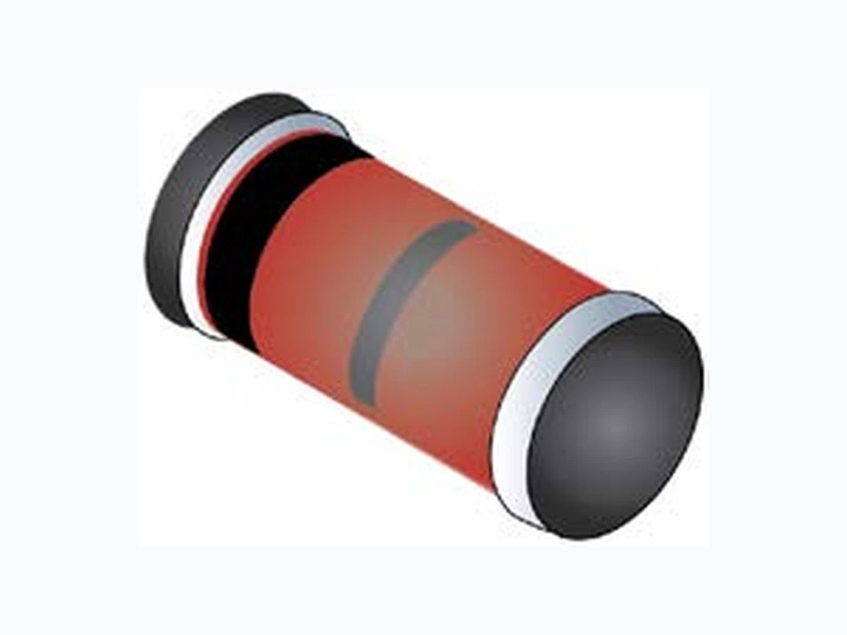
T4-LDS-0232-1, Rev. 1 (111957) ©2011 Microsemi Corporation Page 1 of 6 1N5221BUR-1 thru 1N5281BUR-1 Available on commercial versions METALLURGICALLY BONDED GLASS SURFACE MOUNT 500 mW ZENERS Screening in reference to MIL-PRF-19500 available
DESCRIPTION
The 1N5221BUR-1 thru 1N5281BUR-1 series of 0.5 watt Zener voltage regulators provides a surface mount equivalent to the popular JEDEC registered 1N5221 to 1N5281 series for 2.4 to 200 volts in a metallurgically bonded configuration. They are available with standard 5% or 10% tolerances as well as tighter tolerances identified by different suffix letters on the part number. Microsemi also offers numerous other Zener products to meet higher and lower power applications. Also available in: DO-35 (DO-204AH) (axial-leaded) 1N5221B-1 thru 1N5281B-1 Important: For the latest information, visit our website http://www.microsemi.com.
FEATURES
- Surface mount equivalent of JEDEC registered 1N5221 thru 1N5281 series.
- Voltage tolerances of 10%, 5%, 2%, and 1% available.
- Hermetically sealed surface mount package.
- Internal metallurgical bond.
- Up-screening in reference to MIL-PRF-19500 is available. (See part nomenclature for all available options.)
- RoHS compliant versions available (commercial grade only). APPLICATIONS / BENEFITS
- Regulates voltage over a broad operating current and temperature range.
- Extensive selection from 2.4 to 200 V.
- Non-sensitive to ESD (MIL-STD-750 method 1020).
- Minimal capacitance (see Figure 3).
- Inherently radiation hard per Microsemi “MicroNote 050”. MAXIMUM RATINGS MSC – Lawrence
6 Lake Street,
Lawrence, MA 01841 Tel: 1-800-446-1158 or (978) 620-2600 Fax: (978) 689-0803 MSC – Ireland Gort Road Business Park, Ennis, Co. Clare, Ireland Tel: +353 (0) 65 6840044 Fax: +353 (0) 65 6822298 Website: www.microsemi.com Parameters/Test Conditions Symbol Value Unit Junction and Storage Temperature TJ and TSTG -65 to +175 oC Thermal Resistance Junction-to-Ambient (1) RӨJA 250 oC/W Thermal Resistance Junction-to-End Cap RӨJEC 100 oC/W Steady-State Power Dissipation (2) PD 0.5 W Forward Voltage @ 200 mA VF 1.1 V Solder Temperature @ 10 s TSP 260 oC Notes: 1. When mounted on FR4 PC board (1 oz Cu) with recommended footprint (see last page). 2. At end cap temperature TEC < 125 oC or ambient temperature TA < 50 ºC when mounted on FR4 PC board as described for thermal resistance above (see Figure 2 for derating).
T4-LDS-0232-1, Rev. 1 (111957) ©2011 Microsemi Corporation Page 2 of 6 1N5221BUR-1 thru 1N5281BUR-1 MECHANICAL and PACKAGING
- CASE: Hermetically sealed glass DO-213AA (SOD80 or MLL34) MELF style package.
- TERMINALS: End caps tin-lead or RoHS compliant annealed matte-tin plating (commercial grade only) solderable per MIL-STD- 750, method 2026.
- MARKING: Cathode band only.
- POLARITY: Cathode indicated by band where diode is to be operated with the banded end positive with respect to the opposite end for Zener regulation.
- TAPE & REEL option: Standard per EIA-481-B (add “TR” suffix to part number). Consult factory for quantities.
- WEIGHT: 0.04 grams.
- See Package Dimensions on last page. PART NOMENCLATURE MQ 1N5221 B UR -1 (e3) Reliability Level MQ (reference JAN) MX (reference JANTX) MV (reference JANTXV) MSP (reference JANS) Blank = Commercial JEDEC type number (see Electrical Characteristics table) Zener Voltage Tolerance A = 10% B = 5% C = 2% D = 1% RoHS Compliance e3 = RoHS Compliant (available on commercial grade only) Blank = non-RoHS Compliant Metallurgically Bonded Surface Mount Package SYMBOLS & DEFINITIONS Symbol Definition IR Reverse Current: The maximum reverse (leakage) current that will flow at the specified voltage and temperature. IZ, IZT, IZK Regulator Current: The dc regulator current (IZ), at a specified test point (IZT), near breakdown knee (IZK). IZM Maximum Regulator (Zener) Current: The maximum rated dc current for the specified power rating. TSP Temperature Solder Pad: The maximum solder temperature that can be safely applied to the terminal. VR Reverse Voltage: The reverse voltage dc value, no alternating component. VZ Zener Voltage: The Zener voltage the device will exhibit at a specified current (IZ) in its breakdown region. ZZT or ZZK Dynamic Impedance: The small signal impedance of the diode when biased to operate in its breakdown region at a specified rms current modulation (typically 10% of IZT or IZK) and superimposed on IZT or IZK respectively.
T4-LDS-0232-1, Rev. 1 (111957) ©2011 Microsemi Corporation Page 3 of 6 1N5221BUR-1 thru 1N5281BUR-1 ELECTRICAL CHARACTERISTICS @ 25 oC unless otherwise noted.* INDUSTRY PART NUMBER (Notes 1 & 4) Nominal Zener Voltage VZ @ IZT (Note 2) Volts Test Current IZT mA Max Zener Impedance Max Reverse Leakage Current Max Zener Voltage Temp. Coeff. (Note 3) αVZ (% / oC) ZZT @ IZT Ohms ZZK @ IZK = 0.25 mA Ohms IR @ VR µA Volts A B,C & D 1N5221BUR-1 1N5222BUR-1 1N5223BUR-1 1N5224BUR-1 1N5225BUR-1 2.4 2.5 2.7 2.8 3.0 1200 1250 1300 1400 1600 100 100 0.95 0.95 0.95 0.95 0.95 1.0 1.0 1.0 1.0 1.0 -0.085 -0.085 -0.080 -0.080 -0.075 1N5226BUR-1 1N5227BUR-1 1N5228BUR-1 1N5229BUR-1 1N5230BUR-1 3.3 3.6 3.9 4.3 4.7 1600 1700 1900 2000 1900 5.0 0.95 0.95 0.95 0.95 1.9 1.0 1.0 1.0 1.0 2.0 -0.070 -0.065 -0.060 +/-0.055 +/-0.030 1N5231BUR-1 1N5232BUR-1 1N5233BUR-1 1N5234BUR-1 1N5235BUR-1 5.1 5.6 6.0 6.2 6.8 7.0 7.0 5.0 1600 1600 1600 1000 750 5.0 5.0 5.0 5.0 3.0 1.9 2.9 3.3 3.8 4.8 2.0 3.0 3.5 4.0 5.0 +/-0.030 +0.038 +0.038 +0.045 +0.050 1N5236BUR-1 1N5237BUR-1 1N5238BUR-1 1N5239BUR-1 1N5240BUR-1 7.5 8.2 8.7 9.1 6.0 8.0 8.0 500 500 600 600 600 3.0 3.0 3.0 3.0 3.0 5.7 6.2 6.2 6.7 7.6 6.0 6.5 6.5 7.0 8.0 +0.058 +0.062 +0.065 +0.068 +0.075 1N5241BUR-1 1N5242BUR-1 1N5243BUR-1 1N5244BUR-1 1N5245BUR-1 9.5 9.0 8.5 600 600 600 600 600 2.0 1.0 0.5 0.1 0.1 8.0 8.7 9.4 9.5 10.5 8.4 9.1 9.9 +0.076 +0.077 +0.079 +0.082 +0.082 1N5246BUR-1 1N5247BUR-1 1N5248BUR-1 1N5249BUR-1 1N5250BUR-1 7.8 7.4 7.0 6.6 6.2 600 600 600 600 600 0.1 0.1 0.1 0.1 0.1 11.4 12.4 13.3 13.3 14.3 +0.083 +0.084 +0.085 +0.086 +0.086 1N5251BUR-1 1N5252BUR-1 1N5253BUR-1 1N5254BUR-1 1N5255BUR-1 5.6 5.2 5.0 4.6 4.5 600 600 600 600 600 0.1 0.1 0.1 0.1 0.1 16.2 17.1 18.1 +0.087 +0.088 +0.089 +0.090 +0.091 1N5256BUR-1 1N5257BUR-1 1N5258BUR-1 1N5259BUR-1 1N5260BUR-1 4.2 3.8 3.4 3.2 3.0 600 700 700 800 900 0.1 0.1 0.1 0.1 0.1 +0.091 +0.092 +0.093 +0.094 +0.095 1N5261BUR-1 1N5262BUR-1 1N5263BUR-1 1N5264BUR-1 1N5265BUR-1 2.7 2.5 2.2 2.1 2.0 105 125 150 170 185 1000 1100 1300 1400 1400 0.1 0.1 0.1 0.1 0.1 +0.095 +0.096 +0.096 +0.097 +0.097 1N5266BUR-1 1N5267BUR-1 1N5268BUR-1 1N5269BUR-1 1N5270BUR-1 1.8 1.7 1.5 1.4 1.4 230 270 330 370 400 1600 1700 2000 2200 2300 0.1 0.1 0.1 0.1 0.1 +0.097 +0.098 +0.098 +0.099 +0.099 1N5271BUR-1 1N5272BUR-1 1N5273BUR-1 1N5274BUR-1 1N5275BUR-1 100 110 120 130 140 1.3 1.1 1.0 0.95 0.90 500 750 900 1100 1300 2600 3000 4000 4500 4500 0.1 0.1 0.1 0.1 0.1 101 106 +0.110 +0.110 +0.110 +0.110 +0.110 1N5276BUR-1 1N5277BUR-1 1N5278BUR-1 1N5279BUR-1 1N5280BUR-1 1N5281BUR-1 150 160 170 180 190 200 0.85 0.80 0.74 0.68 0.66 0.65 1500 1700 1900 2200 2400 2500 5000 5500 5500 6000 6500 7000 0.1 0.1 0.1 0.1 0.1 0.1 108 116 123 130 137 144 114 122 129 137 144 152 +0.110 +0.110 +0.110 +0.110 +0.110 +0.110 * TA = +25 oC unless otherwise noted. Based on dc measurements at thermal equilibrium; case temperature maintained at 30 +/- 2 oC. VF = 1.1 V max @ IF = 200 mA for all types. See further notes on following page.
T4-LDS-0232-1, Rev. 1 (111957) ©2011 Microsemi Corporation Page 4 of 6 1N5221BUR-1 thru 1N5281BUR-1 NOTE 1: Table as shown lists type numbers, which indicate a tolerance of +/- 5%. Devices with guaranteed limits on all six parameters are indicated by suffix “A” for +/- 10%, “B” for +/- 5%, “C” for +/- 2%, and “D” for +/- 1% tolerance. NOTE 2: The electrical characteristics are measured after allowing the device to stabilize for 20 seconds. NOTE 3: Temperature coefficient (αvz). Test conditions for temperature coefficient are as follows: a. IZT = 20 mA, T1 = 25 oC, T2 = 125 oC (1N5221AUR-1 & BUR-1 thru 1N5242AUR-1 & BUR-1) b. IZT = Rated IZT, T1 = 25 oC, T2 = 125 oC (1N5243AUR-1 & BUR-1 thru 1N5281AUR-1 & BUR-1) Device to be temperature stabilized with current applied prior to reading breakdown voltage at the specified ambient temperature.
T4-LDS-0232-1, Rev. 1 (111957) ©2011 Microsemi Corporation Page 6 of 6 1N5221BUR-1 thru 1N5281BUR-1 PACKAGE DIMENSIONS PAD LAYOUT DIM INCHES MILLIMETERS MIN MAX MIN MAX A 0.063 0.067 1.60 1.70 B 0.130 0.146 3.30 3.70 C 0.016 0.022 0.41 0.55 INCHES mm A .200 5.08 B .055 1.40 C .080 2.03