
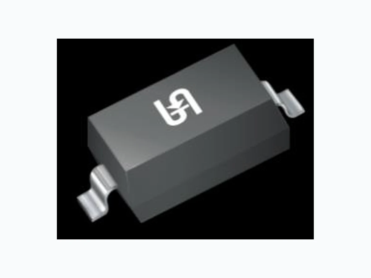
1N4148WH TSC
Document overview
- Manufacturer or author: Provided By digicamel.com
- PDF pages: 5
Technical content
1 Version: A2501
150mA, 100V High Speed Switching Diode
FEATURES
- AEC-Q101 qualified
- Fast switching speed
- Ideal for automated placement
- Moisture sensitivity level: level 1, per J-STD-020
- RoHS Compliant
- Halogen-free
APPLICATIONS
- High-speed switching
- General-purpose switching MECHANICAL DATA
- Case: SOD-123
- Molding compound meets UL 94V-0 flammability rating
- Terminal: Matte tin plated leads, solderable per J-STD-002
- Meet JESD 201 class 2 whisker test
- Polarity: Indicated by cathode band
- Weight: 10.97mg (approximately) KEY PARAMETERS PARAMETER VALUE UNIT IF 150 mA VRRM 100 V IFSM 2 A TJ MAX 150 °C VF at IF=150mA 1.25 V Configuration Single die PACKAGE: SOD-123 PIN CONFIGURATION CIRCUIT DIAGRAM ABSOLUTE MAXIMUM RATINGS (TA = 25°C unless otherwise noted) PARAMETER SYMBOL VALUE UNIT Power dissipation(1) PD 400 mW Repetitive peak reverse voltage VRRM 100 V Average rectified output current IO 150 mA Forward continuous current IFM 300 mA Non-repetitive peak forward surge current t = 1s IFSM 1 A t = 1µs 2 A Junction temperature TJ -55 to +150 °C Storage temperature TSTG -55 to +150 °C Note: 1. Device mounted on an FR4 Printed-Circuit Board (PCB), single-sided copper, tin-plated and standard footprint
2 Version: A2501
Junction-to-ambient thermal resistance(1) RӨJA 312.5 °C/W Thermal Performance Note: 1. Device mounted on an FR4 Printed-Circuit Board (PCB), single-sided copper, tin-plated and standard footprint ELECTRICAL SPECIFICATIONS (TA = 25°C unless otherwise noted) PARAMETER CONDITIONS SYMBOL MIN TYP MAX UNIT Forward voltage(1) IF = 1mA VF - - 0.715 V IF = 10mA - - 0.855 IF = 50mA - - 1.000 IF = 150mA - - 1.250 Reverse breakdown voltage IR = 100μA VBR 100 - - V Reverse current(2) VR = 75V IR - - 0.5 μA VR = 75V, TJ = 150°C - - 50 μA Junction capacitance f = 1MHz, VR = 0V CJ - - 2 pF Reverse recovery time IF = IR = 10mA, IRR = 1mA, RL = 100Ω trr - - 4 ns Notes: 1. Pulse test with PW=0.3 ms 2. Pulse test with PW=30 ms
ORDERING INFORMATION
ORDERING CODE PACKAGE PACKING 1N4148WH RHG SOD-123 3,000 / 7” Tape & Reel
3 Version: A2501
(TA = 25°C unless otherwise noted) Fig.1 Power Dissipation Curve Fig.2 Typical Junction Capacitance Fig.3 Typical Reverse Characteristics Fig.4 Typical Forward Characteristics 100 1000 100 1000 10000 100000 0 20 40 60 80 100 100 150 200 250 300 350 400 450 500 0 25 50 75 100 125 150 0.2 0.4 0.6 0.8 0 10 20 30 40 CAPACITANCE (pF) INSTANTANEOUS REVERSE CURRENT (nA) REVERSE VOLTAGE (V) INSTANTANEOUS FORWARD CURRENT (mA) (A) FORWARD VOLTAGE (V) REVERSE VOLTAGE (V) POWER DISSIPATION (mW) AMBIENT TEMPERATURE ( TJ=25°C TJ=-55°C TJ=150°C TJ=125°C TJ=150°C TJ=125°C TJ=75°C TJ=25°C
4 Version: A2501
0.15 0.05 2.85 2.55 B 1.80 1.40 A DETAIL A C 4 5 0.45 0.25 (0.50) 0.20 1.25 0.95 GAUGE PLANE H H 0.70 0.45
0.13 C A B
0.90 1.00 3.30 3.85 3.55 P/N = MARKING CODE MARKING DIAGRAM P/N CATHODE INDICATOR NOTES: UNLESS OTHERWISE SPECIFIED 1. ALL DIMENSIONS ARE IN MILLIMETERS. 2. DIMENSIONING AND TOLERANCING PER ASME Y14.5M-1994. 3. PACKAGE OUTLINE REFERENCE: JEDEC DO-215, VARIATION AD, ISSUE D.
4 MOLDED PLASTIC BODY DIMENSIONS DO NOT
INCLUDE MOLD FLASH.
5 MOLDED PLASTIC BODY LATERAL DIMENSIONS
TO BE DETERMINED AT DATUM PLANE H. 6. DWG NO. REF: HQ2SD07-SOD123-046 REV A. SUGGESTED PAD LAYOUT 1.35 0.95 0.10 0.00 C SEATING PLANE DETAIL A (SCALE 2:1) T4F F = Device marking = Factory code
5 Version: A2501
Specifications of the products displayed herein are subject to change without notice. TSC or anyone on its behalf, assumes no responsibility or liability for any errors or inaccuracies. Purchasers are solely responsible for the choice, selection, and use of TSC products and TSC assumes no liability for application assistance or the design of Purchasers’ products. Information contained herein is intended to provide a product description only. No license, express or implied, to any intellectual property rights is granted by this document. Except as provided in TSC’s terms and conditions of sale for such products, TSC assumes no liability whatsoever, and disclaims any express or implied warranty, relating to sale and/or use of TSC products including liability or warranties relating to fitness for a particular purpose, merchantability, or infringement of any patent, copyright, or other intellectual property right. The products shown herein are not designed for use in medical, life-saving, or life-sustaining applications. Customers using or selling these products for use in such applications do so at their own risk and agree to fully indemnify TSC for any damages resulting from such improper use or sale.