
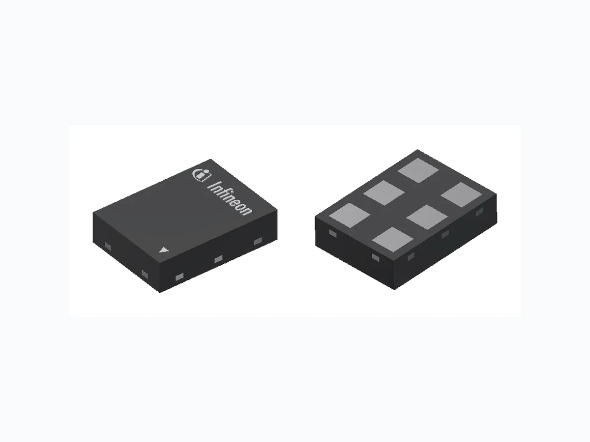
1EDN9550B INFINEON
Document overview
- Manufacturer or author: Provided By digicamel.com
- PDF pages: 31
Technical content
EiceDRIVER™ 1EDNx550 Single-channel high-side and low-side gate driver with high-CMR TDI inputs
Description
EiceDRIVER™1EDNx550 is part of the TDI family of single-channel high- side and low-side gate driver ICs. The TDI family has a fully differential input circuitry. The truly differential inputs (TDI) provide excellent common-mode robustness (CMR) and eliminates the risk of false triggering. The small package footprints enable versatile layout in both low-side and high-side driving. SOT23-6 TSNP-6 Product features Topologies
- Very large common-mode input voltage range (CMR static) up to ±200 V, configurable with common mode resistors
- Separate low impedance source (4 A) and sink (8 A) outputs
- 45 ns propagation delay (-7/+10 ns accuracy)
- Four UVLO options: 4 V, 8 V, 12 V and 15 V
- SOT23-6 or TSNP-6 small packages
- Fully qualified according to JEDEC for industrial grade applications
- 4-pin Kelvin-source MOSFETs in boost PFCs
- Low-side driving with high PCB parasitic inductance
- High-side driving in switched tank converters
- High and low-side driving in half and full-bridges
- Driving SJ and SiC MOSFETs, GaN HEMTs
- Switches requiring negative drive voltage
Applications
- Server, telecom and industrial SMPS
- DC-DC converters and bricks
- Power tools, motor control Table 1 Product portfolio Part number Package UVLO ON/OFF Output current Max. CMR static 1) Max. CMR dynamic 1) 1EDN7550U PG-TSNP-6 4.2 V / 3.9 V -8 A / +4 A ±200 V ± 400 V 1EDN7550B PG- SOT23-6 1EDN8550B 8.0 V / 7.0 V 1EDN6550B 12.2 V / 11.5 V 1EDN9550B 14.9 V / 14.4 V Driving Kelvin source MOSFET Driving medium voltage half-bridge GND OUT_SNK IN - VDD IN + Dboot VDD Vphase SGND VBUS PGND Cboot RgOFF_HS Rboot Controller PWM 1 PWM2 EiceDRIVER™ 1EDNx550 GND SGND Rin-HS Rin+HS RgON_HS RVDD D G S GND OUT_SNK IN - VDD IN + CVDD RgOFF_LS EiceDRIVER™ 1EDNx550 Rin-LS Rin+LS RgON_LS D G S OUT_SR C OUT_SR C ZVDD SGND CVDD Controller vLSLS 4-pin MOSFET D G S SS DVRin GND PWM_Out GND OUT_SNK IN - VDD IN + EiceDRIVER™ 1EDNx550 RIN- OUT_SR C RIN+ PGND VDD SGND RgOFF RgON Figure 1 EiceDRIVER ™ 1EDNx550 driving Kelvin-source MOSFET and half-bridge power stages 1 CMR static and dynamic for the application depends on input resistors. Please see Chapter 6.1 Datasheet Please read the Important Notice and Warnings at the end of this document Rev.2.3 www.infineon.com 2021-11-12
EiceDRIVER™ 1EDNx550 Single-channel high-side and low-side gate driver with high-CMR TDI inputs Table of contents Datasheet 2 Rev.2.3 2021-11-12
1 Pin configuration and description
The pin configuration for both SOT23-6 and TSNP-6 package is illustrated in Figure 2 and a description is given in Table 2 . For functional details, please read Chapter 3. IN- GND IN+ OUT_SNK OUT_SRC VDD SOT23-6 1 6 TSNP-6 IN- GND IN+ OUT_SNK OUT_SRC VDD 1 6 3 4 Figure 2 Pin configuration SOT23-6 and TSNP-6 6-pin packages (top view) Table 2 Pin description Pin number Pin name Description
1 IN- Negative input
connected to controller PWM or ground via input resistor (see Chapter 6)
2 GND Ground
negative gate drive voltage ("off" state voltage)
3 IN+ Positive input
connected to controller PWM or ground via input resistor (see Chapter 6)
4 VDD Supply voltage
positive gate drive voltage ("on" state voltage)
5 OUT_SRC Driver output source
low-impedance switch to VDD (4 A/0.85 Ω)
6 OUT_SNK Driver output sink
low-impedance switch to GND (8 A/0.35 Ω) EiceDRIVER™ 1EDNx550 Single-channel high-side and low-side gate driver with high-CMR TDI inputs Datasheet 3 Rev.2.3 2021-11-12
2 Block diagram
A simplified functional block diagram of EiceDRIVER™ 1EDNx550 is given in Figure 3. IN+ IN- GND VDD OUT_SNK OUT_SRC Differential Schmitt Trigger Diff. Amp. + LPF UVLO Logic Figure 3 Simplified block diagram of EiceDRIVER ™ 1EDNx550 EiceDRIVER™ 1EDNx550 Single-channel high-side and low-side gate driver with high-CMR TDI inputs Datasheet 4 Rev.2.3 2021-11-12
3 Functional description
EiceDRIVER™ 1EDNx550 is a family of high-side and low-side non-isolated gate drivers whose application ranges into fields usually reserved for isolated and level shifter drivers, resulting in significant cost benefits. This is made possible by the unique truly differential input (TDI) stage concept. The TDI input stage allows controlling the driver even if a common-mode voltage is present on the input differential pair. Common-mode voltages up to ±200 V DC and ±400 V AC peak between ground reference (GND) and driver inputs (IN-, IN+) are possible. EiceDRIVER™ 1EDNx550 is suited for any application with unwanted voltage shifts between driver and system ground and in high-side driving within the allowed static common-mode range (±200 V max., see Chapter 6.1). Switches requiring a bipolar driving voltage can be operated easily as well, taking advantage of the common mode voltage handling capability of the TDI.
3.1 Truly differ ential input (TDI)
Figure 4 depicts the signal path from the controller’s PWM output to the logic gate driver signal input as implemented in 1EDNx550. IN+ IN- Differential Schmitt Trigger A v = 4.5
12 MHz
Figure 4 Functional principle of the EiceDRIVER ™ 1EDNx550 with truly differ ential inputs (TDI) The two input resistors Rin1 and Rin2 are mandatory for correct operation of EiceDRIVER™ 1EDNx550 since this gate driver IC cannot be used as a standard low-side driver with IN- directly connected to GND pin. The PWM pin of the controller shall be connected to IN+ pin of EiceDRIVER™ 1EDNx550 through resistor Rin1, while the SGND pin of the controller (or PWM in case of half-bridge configurations) shall be connected to IN- pin through resistor Rin2. The two resistors Rin1 and Rin2, together with the 2 kΩ and 1 kΩ resistors inside the driver, allow to implement a high common-mode rejection ratio (CMRR) differential amplifier that functionally decouples the controller outputs from ground of the gate driver. Rin1 and Rin2 input resistors shall be chosen as a function of the maximum ΔVRin and the required static common-mode voltage between the driver ground and the controller ground, according to Table 16. As an example, for maximum ΔVRin = 3.3 V, Rin1 and Rin2 should be 33 kΩ, resulting in a static divider ratio of k = 12 at the driver inputs, as per the following voltage divider formula: k = (Rin [kΩ] + 3)/3 (1) For ΔVRin other than 3.3 V, Rin1 and Rin2 must fulfill the relation: Rin1 = Rin2 = (10.9 * VS − 3) [kΩ] (2) EiceDRIVER™ 1EDNx550 Single-channel high-side and low-side gate driver with high-CMR TDI inputs Datasheet 5 Rev.2.3 2021-11-12
where VS is the high voltage level of the PWM signal, usually equal to the controller supply voltage. A lookup table is also available in Table 16 as a guide for selecting the value, form factor and tolerance of resistors Rin1 and Rin2. The input signal is then amplified by a factor of 4.5 from the high-CMRR amplifier and filtered by a 2nd order low-pass filter. Considering also the passive differential RC filter in front of the high-CMRR amplifier, the overall input signal experiences 3rd order filtering with a corner frequency at 12 MHz. The suppression of high frequencies is important to dampen ringing at 100 MHz and above in fast-switching power systems and also makes the driver robust against any mismatch of Cp1 and Cp2 input parasitic capacitance (50 to 100 fF range). The filtered signal is then applied to the differential Schmitt-Trigger that feeds a pulse extender. The pulse extender avoids the transfer of PWM signals shorter than 25 ns to the output stage, improving noise immunity. Overall typical input-to-output propagation delay is 45 ns. A propagation delay accuracy of +10/-7 ns is achieved.
3.1.1 Common-mode input range
Due to the passive low-pass filtering at the input side, the CMR (common-mode robustness, i.e. the maximum allowed voltage difference between controller outputs PWM/SGND and driver reference GND) can be split into CMR static and CMR dynamic parameters, depending on the common-mode voltage frequency content. Provided a certain input resistor and controller voltage configuration, the CMR static describes the capability of the driver to withstand DC voltages, while the CMR dynamic describes the capability of the driver to withstand AC voltages due to overshoots or ringing. The CMR capabilities strongly depend on input resistors Rin1 and Rin2. The value and accuracy of resistors must allow to meet the maximum device voltage ratings at IN+/IN- pins while their form factor shall be chosen to meet power dissipation and creepage requirements. In more detail, CMR static is limited by the operating voltage at the input pins IN+/IN- (+6 V/-7 V) to allow input stage to work in linear mode. CMR dynamic is limited by the absolute maximum ratings (+10 V/-10 V) on the same pins. As an example, if 33 kΩ, 0.1% tolerance, 0603 form factor resistors and 3.3 V controller supply voltage are used, this translates into a static CMR range of + 72/- 84 V. Under the same conditions, the maximum input voltage ratings at pins IN+/IN- of ±10 V results in a dynamic CMR range of ±150 V. In case of 127 kΩ, 0.1% tolerance, 1206 form factor resistors and 12 V maximum PWM voltage, the maximum CMR static is ± 200 V and the maximum CMR dynamic is ± 400 V. In case of different PWM voltages and input resistor configurations, please refer the lookup table in Chapter 6.1. The lookup table helps to select the proper resistor parameters (value, form factor, tolerance) depending on the needed CMR parameters and PWM voltage, or to check the maximum allowed CMR depending on the PWM output voltage and input resistors. Please be aware that a perfectly symmetric layout of the input signal path is mandatory to reach the full CMR ranges mentioned above. Any parasitic imbalance in the signal path converts a common-mode signal into a differential signal, resulting in reduced CMR performances. Layout recommendations can be found in Chapter 7.
3.2 Driver outputs
The rail-to-rail driver output stage made with complementary MOS transistors can provide a typical 4 A sourcing and 8 A sinking current. The low on-resistance associated with high driving current is particularly beneficial for fast switching of low RdsON MOSFETs. With a RON of 0.85 Ω for the sourcing pMOS and 0.35 Ω for the sinking nMOS transistor, the driver can be considered to behave as an ideal switch. The p-channel sourcing transistor allows real rail-to-rail behavior without suffering from the voltage drop that is common for n-channel output stages. In case of unconnected inputs, the driver output is actively clamped to the “low” level (GND). EiceDRIVER™ 1EDNx550 Single-channel high-side and low-side gate driver with high-CMR TDI inputs Datasheet 6 Rev.2.3 2021-11-12
3.3 Supply voltage and undervoltage lockout (UVLO)
The undervoltage lockout function ensures that the output can be switched only if the supply voltage VDD exceeds the UVLO threshold voltage. Thus, this feature can ensure that the power switch is not operated with low driving voltage, achieving a complete and fast transition to the "on" state and avoiding excessive power dissipation. Table 3 Logic table ΔVRin UVLO OUT_SRC OUT_SNK x active 2) high impedance L L 3) inactive 4) high impedance L H 5) inactive 4) H high impedance EiceDRIVER™ 1EDNx550 is available in two different packages; the SOT23-6 version offers four UVLO threshold levels to support switches with a broad range of gate source voltages:
- 1EDN7550 with a typical UVLO threshold of 4.2 V (0.3 V hysteresis)
- 1EDN8550 with a typical UVLO threshold of 8 V (1 V hysteresis)
- 1EDN6550 with a typical UVLO threshold of 12.2 V (0.7 V hysteresis)
- 1EDN9550 with a typical UVLO threshold of 14.9 V (0.5 V hysteresis) In addition, the maximum VDD of 20 V makes this driver family well-suited for a broad variety of power switch types such as OptiMOS™ CoolMOS™, CoolGaN™ and CoolSiC™.
2 VDD < UVLOoff
3 ΔVRin < ΔVRinL
4 VDD > UVLOon
5 ΔVRin > ΔVRinH EiceDRIVER™ 1EDNx550 Single-channel high-side and low-side gate driver with high-CMR TDI inputs Datasheet 7 Rev.2.3 2021-11-12
4 Electrical characteristics and parameters
Note: The absolute maximum ratings are listed in Table 4 . Stresses beyond these values may cause permanent damage to the device. Exposure to absolute maximum rating conditions for extended periods may affect device reliability.
4.1 Absolute maximum ratings
Table 4 Absolute maximum ratings Parameter Symbol Values Unit Note or Test Condition Min. Typ. Max. Supply voltage VDD -0.3 – 22 V Voltage between VDD to GND Voltage at pins IN+ and IN- VIN -10 – 10 V – Voltage at pin OUT_SRC VOUT_SRC -24 – 0.3 V OUT = low; referred to VDD pin, DC -24 – 2 V OUT = low; referred to VDD pin < 200 ns Voltage at pin OUT_SNK VOUT_SNK -0.3 – 24 V OUT = high; referred to GND pin, DC -2 – 24 V OUT = high, referred to GND pin < 200 ns Peak reverse current at OUT_SNK ISNK_rev -5 – – A < 500 ns Peak reverse current at OUT_SRC ISRC_rev – – 5 A < 500 ns Junction temperature TJ -40 – 150 °C – Storage temperature TS -55 – 150 °C – ESD capability VESD_HBM – – 2 kV Human Body Model (HBM)6) ESD capability VESD_CDM – – 1 kV Charged Device Model (CDM)7) 6 According to ANSI/ESDA/JEDEC JS-001 (discharging 100 pF capacitor through 1.5 kΩ resistor)
7 According to ANSI/ESDA/JEDEC JS-002
EiceDRIVER™ 1EDNx550 Single-channel high-side and low-side gate driver with high-CMR TDI inputs Datasheet 8 Rev.2.3 2021-11-12
4.2 Thermal characteristics
Table 5 Thermal characteristics SOT23-6 package Parameter Symbol Values Unit Note or Test Condition Min. Typ. Max. Thermal resistance junction- ambient 8) RthJA25 – 165.1 – K/W – Thermal resistance junction- case (top) 9) RthJC25 – 79.9 – K/W – Thermal resistance junction- board 10) RthJB25 – 65.2 – K/W – Characterization parameter junction-case (top) 11) ΨthJC25 – 14 – K/W – Characterization parameter junction-board 12) ΨthJB25 – 51 – K/W – Table 6 Thermal characteristics TSNP-6 package Parameter Symbol Values Unit Note or Test Condition Min. Typ. Max. Thermal resistance junction- ambient 8) RthJA25 – 141 – K/W – Thermal resistance junction- case (top) 9) RthJC25 – 81 – K/W – Thermal resistance junction- board 10) RthJB25 – 36 – K/W – Characterization parameter junction-case (top) 11) ΨthJC25 – 80 – K/W – Characterization parameter junction-board 12) ΨthJB25 – 36 – K/W – 8 Obtained in a simulation on a JEDEC-standard, high-K board, as specified in JESD51-7, in an environment described in JESD51-2a 9 Obtained by simulating a cold plate test on the package top. No specific JEDEC standard test exists, but a close description can be found in the ANSI SEMI standard G30-88 10 Obtained by simulation in an environment with a ring cold plate fixture to control the PCB temperature, as described in JESD51-8 11 Estimates the junction temperature of a device in a real system and is extracted from the simulation data for obtaining Rth, using a procedure described in JESD51-2a (sections 6 and 7) 12 Estimates the junction temperature of a device in a real system and is extracted from the simulation data for obtaining Rth, using a procedure described in JESD51-2a (sections 6 and 7) EiceDRIVER™ 1EDNx550 Single-channel high-side and low-side gate driver with high-CMR TDI inputs Datasheet 9 Rev.2.3 2021-11-12
4.3 Operating range
Parameter Symbol Values Unit Note or Test Condition Min. Typ. Max. Supply voltage VDD 4.5 – 20 V Min defined by UVLO Voltage at pins IN+ and IN- VIN -7 – 6 V – Junction temperature TJ -40 – 150 °C 13)
4.4 Electrical characteristics
Unless otherwise noted, min./max. values of characteristics are the lower and upper limits, respectively. They are valid within the full operating range. The supply voltage is VDD = 12 V unless otherwise specified. Typical values are given at TJ = 25°C Table 8 Power supply Parameter Symbol Values Unit Note or Test Condition Min. Typ. Max. VDD quiescent current IVDDh – 1.1 – mA OUT = high VDD = 12 V VDD quiescent current IVDDh – 1.3 – mA OUT = high VDD = 18 V 14) VDD quiescent current IVDDl – 0.9 – mA OUT = low VDD = 12 V VDD quiescent current IVDDl – 1.0 – mA OUT = low VDD = 18 V 14) Table 9 Undervoltage Lockout 1EDN7550x (Logic level MOSFET) Parameter Symbol Values Unit Note or Test Condition Min. Typ. Max. Undervoltage Lockout (UVLO) turn on threshold UVLOon 3.9 4.2 4.5 V – Undervoltage Lockout (UVLO) turn off threshold UVLOoff 3.6 3.9 – V – UVLO threshold hysteresis UVLOhys 0.25 0.3 0.35 V –
13 Continuous operation above 125°C may reduce life time
14 Parameter verified by design/characterization, not 100% tested in production
EiceDRIVER™ 1EDNx550 Single-channel high-side and low-side gate driver with high-CMR TDI inputs Datasheet 10 Rev.2.3 2021-11-12
Table 10 Undervoltage Lockout 1EDN8550B (Standard MOSFET) Parameter Symbol Values Unit Note or Test Condition Min. Typ. Max. Undervoltage Lockout (UVLO) turn on threshold UVLOon 7.4 8.0 8.6 V – Undervoltage Lockout (UVLO) turn off threshold UVLOoff 6.6 7.0 – V – UVLO threshold hysteresis UVLOhys 0.8 1.0 1.2 V – Table 11 Undervoltage Lockout 1EDN6550B (12 V UVLO option) Parameter Symbol Values Unit Note or Test Condition Min. Typ. Max. Undervoltage Lockout (UVLO) turn on threshold UVLOon 11.7 12.2 12.7 V – Undervoltage Lockout (UVLO) turn off threshold UVLOoff 11.0 11.5 – V – UVLO threshold hysteresis UVLOhys 0.5 0.7 0.9 V – Table 12 Undervoltage Lockout 1EDN9550B (15 V UVLO option) Parameter Symbol Values Unit Note or Test Condition Min. Typ. Max. Undervoltage Lockout (UVLO) turn on threshold UVLOon 14.4 14.9 15.4 V – Undervoltage Lockout (UVLO) turn off threshold UVLOoff 13.9 14.4 – V – UVLO threshold hysteresis UVLOhys 0.3 0.5 0.7 V – Table 13 Inputs IN+, IN- Parameter Symbol Values Unit Note or Test Condition Min. Typ. Max. Differential input voltage threshold for transition LH (at input resistor) ∆VRinH – 1.7 – V Independent of VDD Rin1 = Rin2 = 33 kΩ 15) Differential input voltage threshold for transition HL (at input resistor) ∆VRinL – 1.5 – V Independent of VDD Rin1 = Rin2 = 33 kΩ 15) Total input resistance on each leg Rin1, Rin2 – 36 – kΩ Rin1 = Rin2 = 33 kΩ 15) 15 see Figure 1 EiceDRIVER™ 1EDNx550 Single-channel high-side and low-side gate driver with high-CMR TDI inputs Datasheet 11 Rev.2.3 2021-11-12
Table 14 Static output characteristics Parameter Symbol Values Unit Note or Test Condition Min. Typ. Max. High-level (sourcing) output resistance Ron_SRC – 0.85 – Ω ISRC = 50 mA Sourcing output current ISRC_pk – 4.0 – A 16) VDD = 12 V Sourcing output current ISRC_pk – 5.2 – A 16) VDD = 18 V Low-level (sinking) output resistance Ron_SNK – 0.35 – Ω ISNK = 50 mA Sinking output current ISNK_pk – -8.0 – A 17) VDD = 12 V Sinking output current ISNK_pk – -9.4 – A 17) VDD = 18 V Table 15 Dynamic characteristics Parameter Symbol Values Unit Note or Test Condition Min. Typ. Max. Input-to-output propagation delay turn-on tPDon 38 45 55 ns CL = 200 pF Input-to-output propagation delay turn-off tPDoff 38 45 55 ns CL = 200 pF Rise time trise – 6.5 15 ns 18) CL = 1.8 nF Fall time tfall – 4.5 15 ns 18) CL = 1.8 nF Rise time trise – 1 5 ns 18) CL = 200 pF Fall Time tfall – 1 5 ns 18) CL = 200 pF Minimum input pulse width that changes output state tPW – 25 – ns 18) CL = 1.8 nF For an illustration of the dynamic characteristics see Figure 6 and Figure 7 Figure 5 gives the circuit used for parameter testing 16 Actively limited to approx. 5.2 Apk; not subject to production test - verified by design/characterization 17 Actively limited to approx. -10.4 Apk; not subject to production test - verified by design/characterization
18 Parameter verified by design, not 100% tested in production
EiceDRIVER™ 1EDNx550 Single-channel high-side and low-side gate driver with high-CMR TDI inputs Datasheet 12 Rev.2.3 2021-11-12
OUT_SNK V DD IN- 33k SGNDD V Rin GND C VDD VDD OUT_SR C C L 33k EiceDRIVER™ 1EDNx550 Figure 5 Test circuit
4.5 Timing diagram
Figure 6 depicts rise, fall and delay times as given in the Chapter 4. IN+ - IN- OUTx t PDon 50% t PDoff 10% 90% t rise t fall 1.7 1.5 Figure 6 Propagation delay, rise and fall time Figure 7 illustrates the undervoltage lockout function. OUTx V DD UVLO on UVLO off Figure 7 UVLO behavior (output state high) EiceDRIVER™ 1EDNx550 Single-channel high-side and low-side gate driver with high-CMR TDI inputs Datasheet 13 Rev.2.3 2021-11-12
5 Typical characteristics
- Undervoltage lockout threshold (1EDN7550) vs temperature 2. Undervoltage lockout threshold (1EDN8550) vs temperature 3.7 3.9 4.1 4.3 4.5 -50 0 50 100 150 VDD [V] Tj [ °C] UVLO on UVLO off 6.4 6.8 7.2 7.6 8.0 8.4 8.8 -50 0 50 100 150 VDD [V] Tj [°C] UVLO on UVLO off 3. Undervoltage lockout threshold (1EDN6550) vs temperature 4. Undervoltage lockout threshold (1EDN9550) vs temperature EiceDRIVER™ 1EDNx550 Single-channel high-side and low-side gate driver with high-CMR TDI inputs
Datasheet 14 Rev.2.3 2021-11-12
- Differ ential input voltage threshold vs temperature 6. Typical quiescent current vs temperature 1.1 1.3 1.5 1.7 1.9 2.1 2.3 2.5 -50 0 50 100 150 Tj [°C] ON threshold OFF threshold VDD=12V Vin=3.3V ∆ VRin [V] 7. Typical quiescent current vs supply voltage 8. Total operating current consumption with capacitive load vs frequency 0.6 0.7 0.8 0.9 1.0 1.1 1.2 1.3 1.4 1.5 1.6 0 5 10 15 20 25 VDD [V] OUT High OUT Low IVDD [mA] 0 200 400 600 800 1000 Frequency [kHz] VDD 4.5V VDD 12V VDD 20V Duty Cycle 50% CL = 1.8nF IVDD [mA] EiceDRIVER™ 1EDNx550 Single-channel high-side and low-side gate driver with high-CMR TDI inputs
Datasheet 15 Rev.2.3 2021-11-12
- Typical propagation delay vs temperature 10. Typical rise and fall time vs temperature EiceDRIVER™ 1EDNx550 Single-channel high-side and low-side gate driver with high-CMR TDI inputs
Datasheet 16 Rev.2.3 2021-11-12
6 Application and implementation
Note: The following information is given as an example for the implementation of the device only and shall not be regarded as a description or warranty of a certain functionality, condition or quality of the device
6.1 Input resistor dimensioning
Table 16 is a lookup table that shows the required input resistor configuration for Rin1 and Rin2 (values, form factor and accuracy) depending on the controller PWM output voltage and the required ground shift robustness (static and dynamic CMR). It can be also used to check the maximum allowed CMR, given a certain resistor and controller configuration. Table 16 Input resistor configuration lookup table Controller PWM output voltage Input resistor configuration Ground shift robustness Value Tolerance Form factor19) CMR static 20) CMR dynamic
2.5 V 24 kΩ 1% ≥0402 -30 V/+30 V ±150 V
0.1% ≥0603 -54 V/+63 V ±150 V
3.3 V 33 kΩ 1% ≥0402 -40 V/+40 V ±150 V
0.1% ≥0603 -72 V/+84 V ±150 V
5 V 51 kΩ 1% ≥0603 -60 V/+60 V ±150 V
0.1% ≥0805 -108 V/+126 V ±200 V
12 V 127 kΩ 1% ≥0805 -140 V/+140 V ±200 V
1% ≥1206 -140 V/+140 V ±400 V 0.1% ≥1206 -200 V/+200 V ±400 V
15 V 160 kΩ 1% ≥0805 -150V/+150 V ±200 V
1% ≥1206 -175 V/+175 V ±400 V 0.1% ≥1206 -200 V/+200 V ±400 V Note: For further information please see the Application Note of EiceDRIVER ™ 1EDNx550 single channel with truly differential inputs found in reference [1]
6.2 Half-bridge driving
The EiceDRIVER™ 1EDNx550 is designed to drive low-side MOSFETs in applications with AC ground-shift between the controller IC and the driver. However, its properties also make it suitable for use in half-bridge or full-bridge configurations, as shown in Figure 8. The EiceDRIVER™ 1EDNx550 can effectively drive high-side devices, replacing level-shift gate driver ICs in half and full-bridge topologies. In the half-bridge structure in Figure 8, when the high-side switch is conducting, a DC offset equal to VBUS occurs between the ground of the high-side driver (i.e. the phase node) and the controller ground. The differential
19 Please check PWM signal duty cycle and resistor power rating
20 Driver ground to system ground
EiceDRIVER™ 1EDNx550 Single-channel high-side and low-side gate driver with high-CMR TDI inputs Datasheet 17 Rev.2.3 2021-11-12
behavior of the EiceDRIVER™ 1EDNx550 enables to handle the floating voltage at the switching node up to the CMR static level stated in Table 16 (e.g. up to 84 V for 3.3 V PWM outputs and 33 kΩ ±0.1% input resistors in 0603 form factor). Common applications are buck converters, full-bridge converters, synchronous rectifiers and motor drive stages. GND OUT_SNK IN - VDD IN + D boot V DD V phase SGND PGND V Bus PGND C boot R gOFF_HS R boot Controller PWM 1 PWM2 EiceDRIVER™ 1EDNx550 GND SGND R in-HS R in+HS R gON_HS R VDD D G S GND OUT_SNK IN - VDD IN + C VDD R gOFF_HS EiceDRIVER™ 1EDNx550 R in-LS R in+LS R gON_HS D G S OUT_SR C OUT_SR C Figure 8 EiceDRIVER ™ 1EDNx550 in half-bridge applications
6.3 Switches with Kelvin-source connection (4-pin packages)
The 4-pin configuration depicted in Figure 9 is a very effective measure to improve the switching performance of transistors in packages with high source inductance LS as is typical for the widely used TO packages. Although the Kelvin-source connection SS solves the problem of the largely increased switching losses due to LS, it is evident that the gate driver reference potential moves by an inductive voltage drop, VLS with respect to the system ground, SGND. In fast-switching applications at high current, VLS can reach 100 V and above. This is the reason 4-pin systems so far either used isolated drivers or external filters with relatively low corner frequency that add significant signal delay. The EiceDRIVER™ 1EDNx550 is effective in this use case and provides an optimum solution. Figure 9 also indicates that the usually SGND-related VDD cannot be used directly as the driver supply. But due to the high frequency of VLS (> 100 MHz), a filter composed of impedance ZVDD together with the bypass capacitor CVDD is well suited to generate a sufficiently stable driver supply. ZVDD can be either a resistor (e.g. 22 Ω with a typical CVDD of 1 µF) or a proper ferrite bead. EiceDRIVER™ 1EDNx550 Single-channel high-side and low-side gate driver with high-CMR TDI inputs Datasheet 18 Rev.2.3 2021-11-12
OUT_SNK V DD IN- R gon R goffR in1 SGND GND C VDD Z VDD R in2 VDDPWM_Out GND Controller v LS L S MOSFET D G S SS OUT_SRC EiceDRIVER™ 1EDNx550 PGND SGND D V Rin Figure 9 EiceDRIVER ™ 1EDNx550 driving a Kelvin-source 4 pin MOSFET
6.4 Applications with significant parasitic PCB-inductances
In fast switching power systems the parasitic inductance associated with any electrical connection may cause significant inductive voltage drops, particularly if the PCB-layout cannot be optimized or if the controller and the power stage are located on two different PCBs. In such situations, the high robustness of EiceDRIVER™ 1EDNx550 against switching noise and ground shifts is extremely valuable and allows good performances even in systems with poor PCB layouts. Figure 10 indicates the most relevant parasitic PCB-inductances and how the EiceDRIVER™ 1EDNx550 can be configured in this application. IN+ OUT_SNK V DD IN- R gon R goffR in1 SGND GND C VDD Z VDD R in2 VDD OUT_SR C PWM_Out GND Controller MOSFET D G S EiceDRIVER™ 1EDNx550 SGND L par2 L par3L par1 D V Rin Figure 10 EiceDRIVER ™ 1EDNx550 in applications with significant PCB inductances EiceDRIVER™ 1EDNx550 Single-channel high-side and low-side gate driver with high-CMR TDI inputs Datasheet 19 Rev.2.3 2021-11-12
6.5 Switches with bipolar gate drive
Although most power switches operate at zero “off” gate to source voltage, a negative Vgs could be required for some devices by specifications or to prevent induced turn-on in case of fast voltage transients or charge injection on the gate node. Consequently, a bipolar supply voltage rail can be required for the gate driver to ensure proper MOSFETs, SiC, and GaN driving. EiceDRIVER™ 1EDNx550 can easily drive power switches requiring bipolar Vgs voltage: Figure 11 shows a layout- effective method to create two supplies out of a single one through a biased Zener diode. In this simple configuration, the bias voltage VB defines the positive Vgs driving voltage, while the negative Vgs driving voltage is given by the voltage difference VB - VDD. OUT_SNK R gON R gOFF R in1 R in2 SGND Controller OUT_SR C VDD V DD IN+ IN- GND PWM_Out SGND R s V B MOSFETEiceDRIVER™ 1EDNx550 D G S C s2 C s1 PGND D V Rin V SS Figure 11 Bipolar gate drive for 3-pin MOSFET EiceDRIVER™ 1EDNx550 Single-channel high-side and low-side gate driver with high-CMR TDI inputs Datasheet 20 Rev.2.3 2021-11-12
7 Layout guidelines
It is well-known that the layout of a fast-switching power system is a critical task with strong influence on the overall performance. This is why there exists a huge number of rules, recommendations, guidelines, tips and tricks that should help to finally end up with a proper system layout. EiceDRIVER™ 1EDNx550 simplifies the design of the grounding network. Maximum performance and CMR capabilities provide a specific input resistor configuration and can be achieved by the following design rules:
- place input resistors Rin close to the driver and make layout of input signal path as symmetric and as compact as possible
- use a low-ESR decoupling capacitance for the VDD supply and place it as close as possible to the driver
- minimize power loop inductance as the most critical limitation of switching speed due to the resulting unavoidable voltage overshoots A layout recommendation for the input path of the SOT23-6 package version is given in Figure 12. CVDD RGON RGOFFRIN1 RIN2 RVDD GND IN- IN+ OUT_SNK OUT_SRC VDD IN_N IN_P VIN OUT DRV_GND 1EDN7550 Figure 12 Layout recommendation for SOT23-6 package As in the case of the TSNP-6 package routing in a single PCB layer is not possible, the layout can be changed according to Figure 13 . The chosen form factor of the input resistors (0603) allows to utilize the full dynamic common-mode input range of ±150 V. 1EDN7550U layout recommendation (max +/- 150V ringing) CVDD RGON RGOFFRIN1 RIN2 RVDD GND IN- IN+ OUT_SNK OUT_SRC IN_N IN_P VIN OUT DRV_GND 1EDN7550U Figure 13 Layout recommendation for TSNP-6 package with SMD resistor 0603 EiceDRIVER™ 1EDNx550 Single-channel high-side and low-side gate driver with high-CMR TDI inputs
Datasheet 21 Rev.2.3 2021-11-12
For applications that do not require the maximum CMR an even more compact layout utilizing resistors of form factor 0402 is shown in Figure 14. 1EDN7550U layout recommendation (max +/- 40V) CVDD RGON RGOFF RIN1 RIN2 RVDD GND IN- IN+ OUT_SNK OUT_SRC VDD IN_N IN_P VIN OUT DRV_GND 1EDN7550U Figure 14 Layout recommendation for TSNP-6 package with SMD resistor 0402 For further layout recommendations for TSNP-6, see Recommendations for Printed Circuit Board Assembly of Infineon TSLP/TSSLP/TSNP Packages [2]. When conductive pollution could occur, please consider coating for PCB in order to prevent the leakage current over external resistor pair that might reduce its accuracy. EiceDRIVER™ 1EDNx550 Single-channel high-side and low-side gate driver with high-CMR TDI inputs Datasheet 22 Rev.2.3 2021-11-12
8 Package information
8.1 Device numbers and markings
Table 17 Device numbers and markings Part number Orderable part number (OPN) Device marking 1EDN7550U 1EDN7550UXTSA1 70 1EDN7550B 1EDN7550BXTSA1 70 1EDN8550B 1EDN8550BXTSA1 80 1EDN6550B 1EDN6550BXTSA1 60 1EDN9550B 1EDN9550BXTSA1 90
8.2 PG-SOT23-6 package
1) DOES NOT INCLUDE PLASTIC OR METAL PROTRUSION OF 0.15 MAX. PER SIDE BOTTOM VIEW INDEX MARKING ALL DIMENSIONS ARE IN UNITS MM THE DRAWING IS IN COMPLIANCE WITH ISO 128 & PROJECTION METHOD 1 [ ] GAUGE PLANE 1.15±0.15 1.25±0.2 0.1±0.05 0.1 C SEATING PLANE COPLANARITY C 0.45±0.1 2.8 2.9 0.25 STAND OFF (0.85)
0.15 C A-B 2x
1.6
0.15 C D 2x
0.2 C 6x
0.4±0.1 6x0.2 C A B 0.95 1)1) D A B 0°..8° 0.125 +0.075 -0.045 1 3 4 6 Figure 15 PG-SOT23-6 outline EiceDRIVER™ 1EDNx550 Single-channel high-side and low-side gate driver with high-CMR TDI inputs Datasheet 23 Rev.2.3 2021-11-12
copper solder mask stencil apertures ALL DIMENSIONS ARE IN UNITS MM 0.95 0.5 0.8 1.21.2 1.21.2 0.8 0.95 0.5 Figure 16 PG-SOT23-6 footprint ALL DIMENSIONS ARE IN UNITS MM THE DRAWING IS IN COMPLIANCE WITH ISO 128 & PROJECTION METHOD 1 [ ] PIN 1 INDEX MARKING 0.25 1.553.3 3.2 Figure 17 PG-SOT23-6 packaging EiceDRIVER™ 1EDNx550 Single-channel high-side and low-side gate driver with high-CMR TDI inputs Datasheet 24 Rev.2.3 2021-11-12
Date code (YW) Type code Figure 18 Package marking (PG-SOT23-6) Note: Date code digits Y and W in Table 18 and Table 19 Table 18 Year date code marking - digit "Y" Year Y Year Y Year Y 2000 0 2010 0 2020 0 2001 1 2011 1 2021 1 2002 2 2012 2 2022 2 2003 3 2013 3 2023 3 2004 4 2014 4 2024 4 2005 5 2015 5 2025 5 2006 6 2016 6 2026 6 2007 7 2017 7 2027 7 2008 8 2018 8 2028 8 2009 9 2019 9 2029 9 Table 19 Week date code marking - digit "W" Week W Week W Week W Week W Week W
1 A 12 N 23 4 34 h 45 v
2 B 13 P 24 5 35 j 46 x
3 C 14 Q 25 6 36 k 47 y
4 D 15 R 26 7 37 l 48 z
5 E 16 S 27 a 38 n 49 8
6 F 17 T 28 b 39 p 50 9
7 G 18 U 29 c 40 q 51 2
8 H 19 V 30 d 41 r 52 3
9 J 20 W 31 e 42 s – –
10 K 21 Y 32 f 43 t – –
11 L 22 Z 33 g 44 u – –
EiceDRIVER™ 1EDNx550 Single-channel high-side and low-side gate driver with high-CMR TDI inputs Datasheet 25 Rev.2.3 2021-11-12
8.3 PG-TSNP-6 package
A 1.1±0.05 1.5±0.05 B (LASERED) 0.1 A 0.1 B 3 4 0.3±0.05 0.3±0.05 ALL DIMENSIONS ARE IN UNITS MM THE DRAWING IS IN COMPLIANCE WITH ISO 128 & PROJECTION METHOD 1 [ ] 0.375±0.025 0.02 MAX. STANDOFF 0.6 0.5 Figure 19 PG-TSNP-6 outline copper solder mask stencil apertures Optional solder mask dam 0.35 0.5 0.6 0.35 0.5 0.6 0.35 ALL DIMENSIONS ARE IN UNITS MM Figure 20 PG-TSNP-6 footprint EiceDRIVER™ 1EDNx550 Single-channel high-side and low-side gate driver with high-CMR TDI inputs Datasheet 26 Rev.2.3 2021-11-12
0.5 1.3 1.7 ALL DIMENSIONS ARE IN UNITS MM THE DRAWING IS IN COMPLIANCE WITH ISO 128 & PROJECTION METHOD 1 [ ] Figure 21 PG-TSNP-6 packaging Pin 1 marking Date code (YW) Type code Figure 22 Package marking (PG-TSNP-6) Note: Date code digits Y and W in Table 18 and Table 19 Further information on packages: www.infineon.com/packages EiceDRIVER™ 1EDNx550 Single-channel high-side and low-side gate driver with high-CMR TDI inputs Datasheet 27 Rev.2.3 2021-11-12
9 List of abbreviations
Table 20 List of abbreviations Acronym Description CMR common-mode robustness CMRR common-mode rejection ratio ESD electrostatic discharge ESR equivalent series resistance GND ground GaN gallium nitride LPF low pass filter OPN orderable part number PCB printed circuit board SiC silicon carbide SOT small outline transistor SMD surface mount device TDI truly differential input TO transistor outline TSNP thin small discrete package UVLO undervoltage lockout EiceDRIVER™ 1EDNx550 Single-channel high-side and low-side gate driver with high-CMR TDI inputs Datasheet 28 Rev.2.3 2021-11-12
[1] InfineonApplications of 1EDNx550 single-channel low-side EiceDRIVER™with truly differential inputs (Rev.1.1), 2019-08-07, [Infineon-ApplicationNote_EiceDRIVER_1EDN_TDI_1EDNx550] [2] Infineon Recommendations for Printed Circuit Board Assembly of Infineon TSLP /TSSLP /TSNP Packages, June 2010, [Recommendations for printed circuit board assembly of Infineon TSLP/TSSLP/TSNP packages EiceDRIVER™ 1EDNx550 Single-channel high-side and low-side gate driver with high-CMR TDI inputs References Datasheet 29 Rev.2.3 2021-11-12
Revision history
Rev.2.3 2021-11-12 • Specifications of 1EDN7550B, 1EDN8550B and 1EDN7550U not changed
- Added new product variants 1EDN6550B and 1EDN9550B
- Updated maximum CMR range to ±200 V static, ±400 V dynamic
- Editorial enhancement of layout and descriptions on front cover
- Editorial enhancement of Pin configuration Table 2
- Editorial enhancement of Functional description in Chapter 3
- Corrected typo ISNK_rev Table 4
- Added UVLO off min. values for all product variants
- Corrected typos in Test circuit Figure 5
- Updated Figure: Typical propagation delay vs temperature in Chapter 5
- Editorial enhancement in Application and implementation Chapter 6
- Added Table 16 in Chapter 6.1
- Added Half-bridge driving in Chapter 6.2
- Editorial enhancement in Layout guidelines Chapter 7
- Chapter Device numbers and markings moved to Chapter 8.1
- Added list of abbreviations in Chapter 9 Rev.2.2 2019-12-19 • Added new product 1EDN7550U with package TSNP-6
- On front cover " Features" , added reference to application note (Applications of 1EDNx550 single-channel lowside EiceDRIVER™ with truly differential inputs.) for input PWM signal voltage levels other than 3.3 V
- Added Table 3, Logic table
- Corrected footnote in Table 4 VESD_HDM
- Updated Max. value in Table 4 VESD_CDM and added footnote
- Updated Thermal characteristics in Table 5 and added Table 6
- Updated Typ. values for Table 8 and added footnotes for Table 15
- Added Figure 5 for Test circuit
- Added layout recommendations for TSNP package Figure 13 and Figure 14
- Added package marking for SOT23 Figure 18 and code marking tables Table 18, Table 19
- Added package marking for TSNP Figure 22
- Added Chapter 8.1, Device numbers and markings Rev. 2.1 2019-11-28 • Parameter split in Table 4 Voltage at pins OUT_SRC and OUT_SNK → Voltage at pin OUT_SRC and Voltage at pin OUT_SNK and specified min. and max.
- Corrected typo in Table 4 VESD_CDM
- To match pin configurations in Figure 2 update of Figure 1 as well as in Chapter 5 the Figure 9 to former Figure: 1EDNx550 as a high-side driver in former Chapter: High-side switches
- Updated diagram according to number of OUT pins → OUTx, Figure 7
- CLoad → CL for Fig 12 and Fig 14
- Updated to latest package diagrams, Chapter 8 Rev. 2.0 2018-05-14 Final Datasheet created EiceDRIVER™ 1EDNx550 Single-channel high-side and low-side gate driver with high-CMR TDI inputs
Datasheet 30 Rev.2.3 2021-11-12
All referenced product or service names and trademarks are the property of their respective owners. Edition 2021-11-12 Published by Infineon Technologies AG
81726 Munich, Germany
© 2021 Infineon Technologies AG All Rights Reserved. Do you have a question about any aspect of this document? Email: erratum@infineon.com Document reference IFX-vbg1622805011331 IMPORTANT NOTICE The information given in this document shall in no event be regarded as a guarantee of conditions or characteristics (“Beschaffenheitsgarantie”). With respect to any examples, hints or any typical values stated herein and/or any information regarding the application of the product, Infineon Technologies hereby disclaims any and all warranties and liabilities of any kind, including without limitation warranties of non-infringement of intellectual property rights of any third party. In addition, any information given in this document is subject to customer’s compliance with its obligations stated in this document and any applicable legal requirements, norms and standards concerning customer’s products and any use of the product of Infineon Technologies in customer’s applications. The data contained in this document is exclusively intended for technically trained staff. It is the responsibility of customer’s technical departments to evaluate the suitability of the product for the intended application and the completeness of the product information given in this document with respect to such application. WARNINGS Due to technical requirements products may contain dangerous substances. For information on the types in question please contact your nearest Infineon Technologies office. Except as otherwise explicitly approved by Infineon Technologies in a written document signed by authorized representatives of Infineon Technologies, Infineon Technologies’ products may not be used in any applications where a failure of the product or any consequences of the use thereof can reasonably be expected to result in personal injury.