
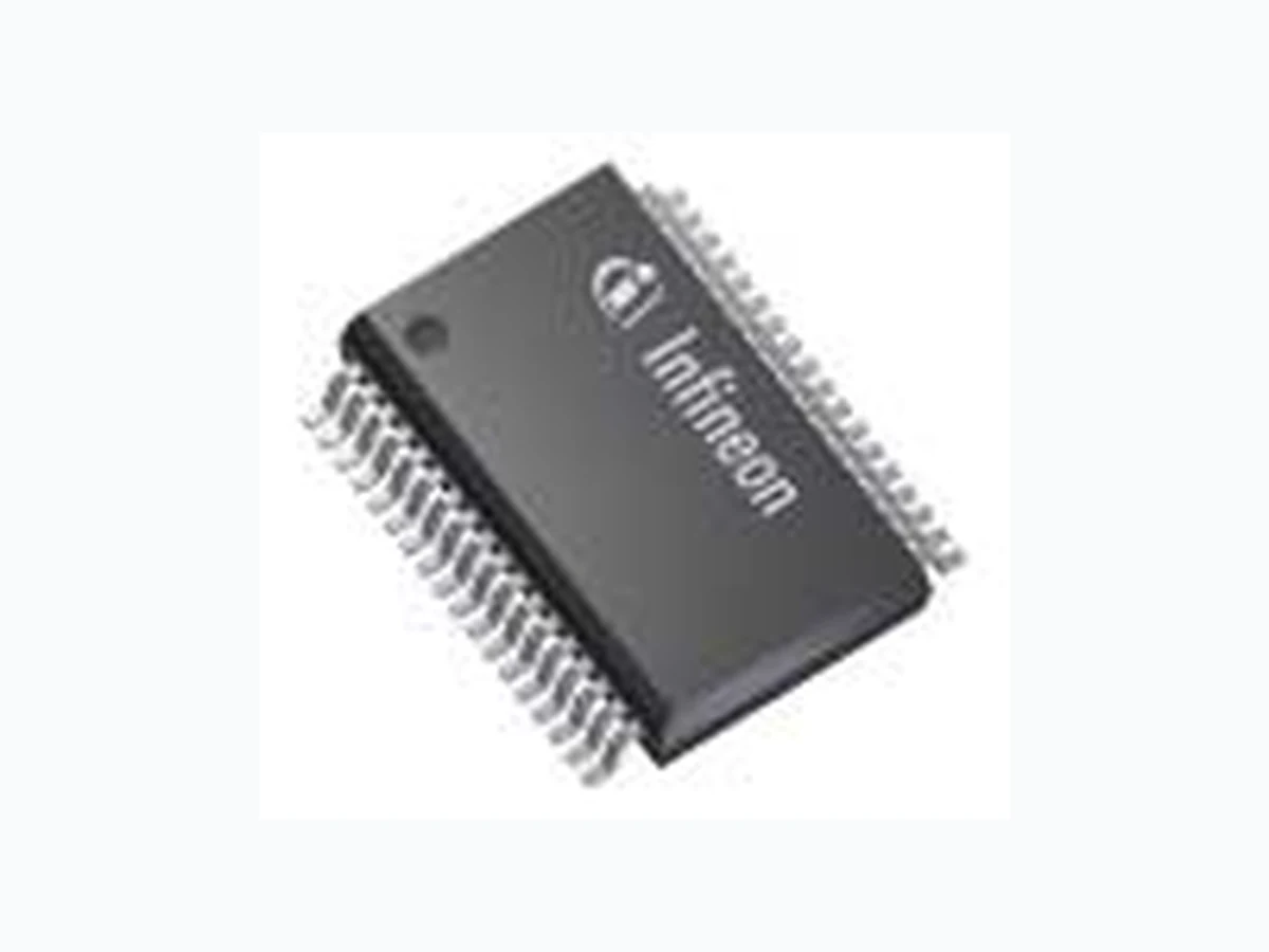
1EDI2004AS INFINEON
Document overview
- Manufacturer or author: Provided By digicamel.com
- PDF pages: 138
Technical content
Features
The following features are supported by the 1EDI2004AS:
- Single Channel IGBT Driver.
- On-chip galvanic insu lation (up to 6kV).
- Support of 600 V and 1200 V IGBT technologies.
- Low propagation delay and minimal PWM distortion.
- Support of 5 V logic levels (primary side).
- 16-bit Standard SPI interface (up to 2 MBau d) with daisy chain support (primary side).
- Enable input pin (primary side).
- Pseudo-differential inputs for cr itical signals (primary side).
- Power-On Reset pin (primary side).
- D e b u g m o d e .
Data Sheet 2 Rev. 2.0 Hardware Description 2019-01-16 EiceDRIVERTM SIL 1EDI2004AS Overview
- Pulse Suppressor.
- Fully Programmable Active Clamping Inhibit signal (secondary side).
- Optimal support of EiceBoost functions.
- Operation with unipolar se condary supply possible (V EE2=VGND2).
- Fullfil BISS standard 2.0 (Cla ss 3) for conducted emissions.
- 36-pin PG-DSO-36 green package.
- Automotive qualified (as per AEC Q100). Safety Relevant Features
- Desaturation monitoring, with sele ctable blanking time in runtime.
- Overcurrent protection.
- Fully programmable Two-Level Turn-Off (static programming).
- A u t o m a t i c E m e r g e n c y T u r n-Off in failure case.
- Externally triggered disabling of the output stage (tristate).
- Under- and over-voltage supervisio n of the secondary power supplies.
- OVLO2 failure reaction can be modified in runtime.
- NFLTA and NFLTB notification pins for fa st system response time (primary side).
- Safe internal state machine.
- Weak Turn-On functionality.
- Internal clock monitoring.
- Gate signal monitoring comparators.
- Individual error and status flags readable via SPI.
- Support for Active Short Circuit strategies.
- Full diagnostic capability.
- In-application testability of safety critical functions.
- Suitable for systems up to ASIL D requirements (as per ISO 26262).
- Compliant to ISO 26262 standard - ASIL A. Target Applications
- Inverters for automotive Hybr id Electric Vehicles (HEV) and Electric Vehicles (EV).
- High Voltage DC/DC converter.
- Industrial Drive. Type Package Marking 1EDI2004AS PG-DSO-36-63 1EDI2004AS
Data Sheet 3 Rev. 2.0, 2019-01-16 Hardware Description Trademarks of Infineon Technologies AG AURIX™, C166™, CanPAK™, CI POS™, CIPURSE™, EconoPAC K™, CoolMOS™, CoolSET™, CORECONTROL™, CROSSAVE™, DAVE™, EasyPIM™, EconoBRIDGE™, Econ oDUAL™, EconoPIM™, EiceDRIVER™, eupec™, FCOS™, HITFET™, HybridPACK™, I²RF™, ISOFACE™, IsoPACK™, MIPAQ™, ModSTACK™, my-d™, NovalithIC™, OptiMOS™, OR IGA™, PRIMARION™, Prim ePACK™, PrimeSTACK™, PRO-SIL™, PROFET™, RASIC™, ReverSave™, SatRIC™, SIEGET™, SINDRION™, SIPMOS™, SmartLEWIS™, SOLID FLASH™, TEMPFE T™, thinQ!™, TRENCH STOP™, TriCore™. Other Trademarks Advance Design System™ (ADS) of Agilent Te chnologies, AMBA™, ARM™, MULTI-ICE™, KEIL™, PRIMECELL™, REALVIEW™, THUMB™, µVision™ of ARM Limited, UK. AUTOSAR™ is licensed by AUTOSAR development partnership. Bluetooth™ of Bluetooth SIG Inc. CAT-iq™ of DECT Forum. COLOSSUS™, FirstGPS™ of Trimble Navigation Ltd. EMV™ of EMVC o, LLC (Visa Holdings In c.). EPCOS™ of Epcos AG. FLEXGO™ of Microsoft Corp oration. FlexRay™ is licensed by FlexRay Consortium. HYPERTERMINAL™ of Hilgraeve Incorporated. IEC™ of Commission Electrot echnique Internationale. IrDA™ of Infrared Data Association Corporation. ISO™ of INTERNATIONAL ORGANIZATION FOR STANDARDIZATION. MATLAB™ of MathWorks, Inc. MAXIM™ of Maxim Integrated Products, Inc. MICROTEC™, NUCLEUS™ of Mentor Graphics of MURATA MANUFACTURING CO., MICROWAVE OFFI CE™ (MWO) of Applied Wave Research Inc., OmniVision™ of OmniVision Technologies, Inc. Open wave™ Openwave Systems Inc. RED HAT™ Red Hat, Inc. RFMD™ RF Micro Devices, Inc. SIRIUS™ of Sirius Sate llite Radio Inc. SOLARIS™ of Sun Microsystems, Inc. SPANSION™ of Spansion LLC Ltd. Symbian™ of Sy mbian Software Limited. TAIYO YUDEN™ of Taiyo Yuden Co. TEAKLITE™ of CEVA, Inc. T EKTRONIX™ of Tektroni x Inc. TOKO™ of TOKO KABUSHIKI KAISHA TA. UNIX™ of X/Open Company Limited. VERILOG™, PALLADIUM™ of Cadence Design Systems, Inc. VLYNQ™ of Texas Instruments Incorporated. VXWORKS™, WIND RIVER™ of WIND RIVER SYSTEMS, INC. ZETEX™ of Diodes Zetex Limited. Last Trademarks Update 2011-02-24
Revision History
Page or Item Subjects (major changes since previous revision) Rev 1.8, 2018-12-19 All, Initial data sheet.
Data Sheet 4 Rev. 2.0, 2019-01-16 Hardware Description Table of Contents
Data Sheet 5 Rev. 2.0, 2019-01-16 Hardware Description
Data Sheet 6 Rev. 2.0, 2019-01-16 Hardware Description
Data Sheet 8 Rev. 2.0, 2019-01-16 Hardware Description Table 45 Electrical Characteristics for Pins: INP, List of Tables
Data Sheet 9 Rev. 2.0, 2019-01-16 Hardware Description
Data Sheet 10 Rev. 2.0 2019-01-16 EiceDRIVERTM SIL 1EDI2004AS Functional Description
2 Functional Description
2.1 Introduction
The 1EDI2004AS is an advanced single channel IGBT dr iver that can also be us ed for driving power MOS devices. The device has been developed in order to op timize the design of high performance safety relevant automotive systems. The device is based on Infineon’s Coreless Transformer Technology and consist of two chips separated by a galvanic isolation. The low voltage (primary) side can be connected to a standard 5 V logic. The high voltage (secondary) side is in the DC-link voltage domain. Internally, the data transfers ar e ensured by two independent comm unication channels. One channel is dedicated to transferring the ON and OFF information of the PWM input signal only. This channel is unidirectional (from primary to se condary). Because this channel is dedicated to the PWM information, latency time and PWM distortion are minimized. The second channel is bi directional and is used for all the other data transfers (e.g. status information, etc). The 1EDI2004AS supports advanced func tions in order to optimize the switching behavior of the IGBT. Furthermore, it supports several monitoring and protec tion functions, making it suitable for systems having to fulfill ASIL requirements (as per ISO 26262).
Data Sheet 11 Rev. 2.0 2019-01-16 EiceDRIVERTM SIL 1EDI2004AS Functional Description
2.2 Pin Configuration and Functionality
2.2.1 Pin Configuration
Figure 1 Pin Configuration Table 1 Pin Configuration Pin Number Symbol I/O Voltage Class Function 1,9,18 VEE2 Supply Supply Negative Power Supply 1). 2 TON Output 15V Secondary Turn-On Output. 2) 3 VCC2 Supply Supply Positive Power Supply. 4 TOFF Output 15V Secondary Turn-Off Output. 2) 5 DESAT Input 15V Secondary Desaturation Protection Input. 6 GATE Input 15V Secondary Gate Monitoring Input. 7 GND2 Ground Ground Ground. 8 IREF2 Input 5V Secondary External Reference Input. 10 VREG Output 5V Secondary Reference Output Voltage. 11 OCP Input 5V Secondary Over Current Protection.
12 OCPG Ground Ground Ground for the OCP function,
13 DEBUG Input 5V Secondary Debug Input. OCPG VREG DESAT IREF2 GND2 TOFF VEE2 NUV2 GAT E DEBUG AMCLP VEE2 OSD VCC2 DACLP OCP TON VEE2 GND1 IN STP EN NRST/RDY Reserved SC LK NFLTA NCS REF0 IN P IREF1 VCC1 GND1 NFLTB 26 SDI GND1 28 SDO Reserved
Data Sheet 12 Rev. 2.0 2019-01-16 EiceDRIVERTM SIL 1EDI2004AS Functional Description 14 DACLP Output 5V Secondary Active Clamping Disable Output.(push-pull) 2) 15 OSD Input 5V Secondary Output Stage Disable Input. 16 AMCLP Output 5V Secondary Active Miller Clamping control output. (push-pull)2) 17 NUV2 Output 5V Secondary V CC2 not valid notification output. (open drain)2) 19, 28, 36 GND1 Ground Ground Ground 3). 20 Reserved Reserved Reserved Reserved. This pin shall be connected to GND1. 21 SCLK Input 5V Primary SPI Serial Clock Input. 22 SDI Input 5V Primary SPI Serial Data Input. 23 NCS Input 5V Primary SPI Chip Select Input (low active). 24 SDO Output 5V Primary SPI Serial Data Output. (push-pull) 25 Reserved Reserved Reserved Reserved. This pin shall be connected to GND1. 26 NFLTB Output 5V Primary Fault B Ou tput (low active, open drain).2) 27 NFLTA Output 5V Primary Fault A Output (low active, open drain). 2) 29 NRST/RDY Input/Output 5V Primary Reset Input (low active, open drain). This signal notifies that the device is “ready”.2) 30 EN Input 5V Primary Enable Input. 31 REF0 Ref. Ground Ground Reference Ground for signals INP, INSTP, EN. 32 INP Input 5V Primary Positive PWM Input. 33 INSTP Input 5V Primary Monitoring PWM Input. 34 VCC1 Supply Input Supply Positive Power Supply. 35 IREF1 Input 5V Primary E xternal Reference Input. 1) All VEE2 pins must be connected together. 2) Pin is not protected against short circuit to respective supply or ground potential. 3) All GND1 pins must be connected together. Table 1 Pin Configuration (cont’d) Pin Number Symbol I/O Voltage Class Function
Data Sheet 13 Rev. 2.0 2019-01-16 EiceDRIVERTM SIL 1EDI2004AS Functional Description
2.2.2 Pin Functionality
2.2.2.1 Primary Side
Ground connection for the primary side. VCC1 5V power supply for the primary side (referring to GND1). INP Non-inverting PWM input of the driver. The internal structure of the pad makes the IC robust against glitches. An internal weak pull-down resistor to VREF0 drives this input to Low state in case the pin is floating. INSTP Monitoring PWM input for shoot thro ugh protection. The internal struct ure of the pad makes the IC robust against glitches. An internal weak pull-down resistor to V REF0 drives this input to Low state in case the pin is floating. REF0 Reference Ground signal for the signals INP, INSTP, EN. This pin should be connected to the ground signal of the logic issuing those signals. EN Enable Input Signal. This signal allows the logic on th e primary side to turn-off and deactivate the device. An internal weak pull-down resistor to VREF0 drives this input to Low state in case the pin is floating. This pin reacts on logic levels. NFLTA Open-Drain Output signal used to report major failure events (Event Class A). In case of an error event, NFLTA is driven to Low state. This pin shall be connected externally to VCC1 with a pull-up resistance. NFLTB Open-Drain Output signal used to report major failure events (Event Class B) and reset events. In case of an error event, NFLTB is driven to Low state. This pin shall be connected externally to V CC1 with a pull-up resistance. SCLK Serial Clock Input for the SPI interface. An internal weak pull-up device to VCC1 drives this input to high state in case the pin is floating. SDO Serial Data Output (push-pull) for the SPI interface.
Data Sheet 14 Rev. 2.0 2019-01-16 EiceDRIVERTM SIL 1EDI2004AS Functional Description SDI Serial Data Input for the SPI interface. An internal weak pull-up device to VCC1 drives this input to high state in case the pin is floating. NCS Chip Select input for the SPI interface. This signal is low active. An internal weak pull-up device to V CC1 drives this input to High state in case the pin is floating. IREF1 Reference input of the primary chip. This pin shall be connected to VGND1 via an external resistor. NRST/RDY Open drain reset input. This signal is low-active. When a valid signal is received on this pin, the device is brought in its default state. This signal is also used as a “ready notification”. A high level on this pin indicates that the primary chip is functional.
2.2.2.2 Secondary Side
Negative power supply for the secondary side, referring to VGND2. VCC2 Positive power supply for the secondary side, referring to VGND2. GND2 Reference ground for the secondary side. DESAT Desaturation Protection input pin. The function associated with this pin monitors the VCE voltage of the IGBT. An internal pull-up resistor to VCC2 drives this signal to High level in case it is floating. OCP Over Current Protection input pin. The function associated with this pin monitors the voltage across a sensing resistance located on the auxiliary path of a Current Sense IGBT. An internal weak pull-up resistor to the internal 5V reference drives this input to High state in case the pin is floating. OCPG Over Current Protection Ground. TON Output pin for turning on the IGBT. TOFF Output pin for turning off the IGBT.
Data Sheet 15 Rev. 2.0 2019-01-16 EiceDRIVERTM SIL 1EDI2004AS Functional Description GATE Input pin used to monitor the IGBT gate voltage. OSD Output Stage Disable input. A High Level on this pin tr istates the output stage. An internal weak pull-down resistor to VGND2 drives this input to Low state in case the pin is floating. DACLP Output pin used to disable the active clamping function of the booster. DEBUG Debug input pin. This pin is latched at power-up. When a High level is detected on this pin, the device enters a special mode where it can be operated without SPI inte rface. This feature is for development purpose only. This pin should normally be tied to VGND2. An internal weak pull-down resistor to VGND2 drives this input to Low state in case the pin is floating. IREF2 Reference input of the secondary chip. This pin shall be connected to VGND2 via an external resistor. VREG Reference Output voltage. This pin shall be connected to an external capacitance to VGND2. NUV2 VCC2 not valid notification signal (Open Drain). This signal drives a low level when VCC2 is below VUVLO2L or when the internal 5V digital supply is not valid. When both supplies are valid, this pin is in high impedance state. This pin shall be connected externally to a 5V reference with a pull-up resistance to ensure level read-out over the respective register. The pin can be connected also to respective ground potential (This enables usage together with OSD pin). AMCLP Active Miller Clamping External Enable Output. The signal goes to High level when V GATE is lower than V GATE1 during turn-off.
2.2.2.3 Pull Devices
Some of the pins are connected internally to pull-up or pull-down devices. This is summarized in Table 2. Table 2 Internal pull devices Signal Device INP Weak pull down to VREF0 INSTP Weak pull down to VREF0 EN Weak pull down to VREF0 SCLK Weak pull up to VCC1 SDI Weak pull up to VCC1 NCS Weak pull up to VCC1
Data Sheet 16 Rev. 2.0 2019-01-16 EiceDRIVERTM SIL 1EDI2004AS Functional Description DESAT Weak pull up to VCC2 OSD Weak pull down to VGND2 OCP Weak pull up to 5V internal reference DEBUG Weak pull down to VGND2 Table 2 Internal pull devices Signal Device
Data Sheet 17 Rev. 2.0 2019-01-16 EiceDRIVERTM SIL 1EDI2004AS Functional Description
2.3 Block Diagram
Data Sheet 18 Rev. 2.0 2019-01-16 EiceDRIVERTM SIL 1EDI2004AS Functional Description
2.4 Functional Block Description
2.4.1 Power Supplies
On the primary side, the 1EDI2004AS needs a single 5Vsupply source VCC1 for proper operation. This makes the device compatible to most of the microcontrollers available for automotive applications. On the secondary side, the 1EDI2004AS needs two power supplies for proper operation.
- The positive power supply V CC2 is typically set to 16.5 V (referring to VGND2).
- The negative supply V EE2 is typically set to -4 V or 0V (referring to VGND2). Under- and over-voltage monitoring is performed continuously during oper ation of the device (see Chapter 3.3.1). A 5V supply for the digital domain on the secondary side is generated internally (present at pin VREG).
2.4.2 Clock Domains
The clock system of the 1EDI2004AS is based on three oscillators defining each a clock domain:
- One RC oscillator (OSC1) for the primary chip.
- One RC oscillator (OSC2) for the seco ndary chip excepting the output stage.
- One Start-Stop oscillator (SSOSC2) for the output stage on the secondary side. The two RC oscillators are running constantly. They are also monitored constantly, and large deviations from the nominal frequency are identified as a system failure (Event Class B, see Chapter 3.3). The Start Stop oscillator is controlled by the PWM command.
Data Sheet 19 Rev. 2.0 2019-01-16 EiceDRIVERTM SIL 1EDI2004AS Functional Description
2.4.3 PWM Input Stage
The PWM input stage generates from the external signals INP, INSTP and EN the turn-on and turn-off commands to the secondary side. The general structure of the PWM input block is shown Figure 3. Figure 3 PWM Input Stage Signals INP, INSTP and EN are pseudo-differential, in the sense th at they are not referenced to the common ground GND1 but to signal REF0. This is intended to make the device more robust against ground bouncing effects. Note: 1. Glitches shorter than t INPS1 (see Table 45) occurring at signal INP are filtered internally. 2. Pulses at INP below tINPPD (see Table 45) might be distorted or suppressed. The 1EDI2004AS supports non-inverted PWM si gnals only. When a High level on pin INP is detected while signals INSTP and EN are valid, a turn-on command is issued to the secondary chip. A Low level at pin INP issues a turn-off command to the secondary chip. Signal EN can inhibit turn-on commands received at pin INP. A valid signal EN is required in order to have turn- on commands issued to the secondar y chip. If an invalid signal is provided, the PWM input stage issues constantly turn-off command s to the secondary chip. Th e functionality of signal EN is detailed in Chapter 2.4.8. Note: After an invalid-to valid-transition of signal EN, a minimum delay of tINPEN should be inserted before turning INP on. As shown in Figure 4, signal INSTP provides a Shoot-Through Protection (STP) to the system. When signal at pin INSTP is at High level, the internal signal inhibit_act is activated. The inhibition time is defined as the pulse duration of signal inhibit_act. It corresponds to the pulse duration of signal INSTP to which a minimum dead time is added. During the inhibition time, rising edges of signal INP are inhibited. Bit PSTAT2.STP is set for the duration of the inhibition time. REF0 LO GIC VCC1 INP INSTP EN pwm_cmd Validity Check en_valid Inhibit Time Generati on inhibit_act .
Data Sheet 21 Rev. 2.0 2019-01-16 EiceDRIVERTM SIL 1EDI2004AS Functional Description
2.4.4 SPI Interface
This chapter describes the functionality of the SPI block.
2.4.4.1 Overview
The standard SPI interface implemented on the 1EDI2004AS is compatible with most of the microcontrollers available for automotive and industrial applications . The following features are supported by the SPI interface:
- Full-duplex bidirectional communication link.
- S P I S l a v e m o d e ( o n l y ) .
- 16-bit frame format.
- Daisy chain capability.
- M S B f i r s t .
- Parity Check (optional) and Parity Bit generation (LSB). The SPI interface of the 1EDI2004AS pr ovides a standardized bidirectiona l communication interface to the main microcontroller. From the architectural point of view, it fulfills the following functions:
- Initialization of the device.
- Configuration of the devi ce (static and runtime).
- Reading of the status of the device (static and runtime).
- Operation of the verification modes of the device. The purpose of the SPI interface is to exchange data which have relaxed timing constraints compared to the PWM signals (from the point of view of the motor control algorithm). The IGBT switching behavior is for example controlled directly by the PWM input. Similarly, critical application failures requiring fast reaction are notified on the primary side via the feedback signals NFLTA, NFLTB and NRST/RDY. In order to minimize the complexity of the end-application and to opti mize the microcontroller’s resources, the implemented interface has daisy chain capabili ty. Several (typically 6) 1EDI2004AS devices can be combined into a single SPI bus.
Data Sheet 22 Rev. 2.0 2019-01-16 EiceDRIVERTM SIL 1EDI2004AS Functional Description
2.4.4.2 General Operation
The SPI interface of the 1EDI2004A S supports full duplex operation. The interface relies on four communication signals:
- NCS: (Not) Chip Select.
- SCLK: Serial Clock.
- SDI: Serial Data In.
- SDO: Serial Data Out. The SPI interface of the 1EDI2004AS supports slave operation only. An SPI master (typ ically, the main microcontroller) is connected to one or several 1EDI2004AS devices, forming an SPI bus. Several bus topologies are supported. A regular SPI bus topology can be used where each of the slaves is controlled by an individual chip select signal (Figure 6). In this case, the number of slaves on the bus is only limited by the application’s constraints. Figure 6 SPI Regular Bus Topology In order to simplify the layout of the PCB and to reduce the number of pins used on the microcontroller’s side, a daisy chain topology can also be used. The chain’s depth is not limited by the 1EDI2004AS itself. A possible topology is shown Figure 7. SCLK Master SDO SDI NCS1 SCLK SDI SDO NCS Slave 1 SCLK SDI SDO NCS Slave 2 SCLK SDI SDO NCS Slave n ... ... ... NCSn... ... NCS2
Data Sheet 23 Rev. 2.0 2019-01-16 EiceDRIVERTM SIL 1EDI2004AS Functional Description Figure 7 SPI Daisy Chain Bus Topology Physical Layer The SPI interface relies on two shift registers:
- A shift output register, reacting on the rising edges of SCLK.
- A shift input register, reacti ng on the falling edges of SCLK. When signal NCS is inactive, the signals at pins SCLK and SDI are ignored. The output SDO is in tristate. When NCS is activated, the shift output register is updated internally with the value requested by the previous SPI access. At each rising edge of the SCLK signal (while NCS is active), the shift output re gister is serially shifted out by one bit on the SDO pin (MSB first). At each falling edge of the clock pulse, the data bit available at the input SDI is latched and serially shifted into the shift input register. At the deactivation of NCS, the SPI logic checks how many rising and falling edges of the SCLK signal have been received. In case both counts differ and / or are not a multiple of 16, an SPI Error is generated. The SPI block then checks the validity of the receiv ed 16-bit word. In case of a non valid data, an SPI error is generated. In case no error is detected, the data is decoded by the internal logic. The NCS signal is active low. Input Debouncing Filters The input stages of signals SDI, SCLK, and NCS include each a Debouncing Filter. The input signals are that way filtered from glitches and noise. The input signals SDI and SCLK are analyzed at each edge of the internal clock derived from OSC1. If the same external signal value is sampled thre e times consecutively, the signal is considered as valid and is processed by the SPI logic. Otherwise, the transition is considered as a glitch and is discarded. SCLK Master SDO SDI NCS SCLK SDI SDO NCS Slave 1 SCLK SDI SDO NCS Slave 2 SCLK SDI SDO NCS Slave n ... ... ... ...
Data Sheet 24 Rev. 2.0 2019-01-16 EiceDRIVERTM SIL 1EDI2004AS Functional Description The input signal NCS is sampled at a rate corresponding to the period of the internal clock derived from OSC1. If the same external signal value is sampled two times consecutively, the signal is considered as valid and is processed by the SPI logic. Otherwise, the transition is considered as a glitch and is discarded.
2.4.4.3 Definitions
A command is a high-level command issued by the SPI master which aims at generating a specific reaction in the addressed slave. The command is physically translated into a Requ est Message by the SPI master. The correct reception of the Request Message by the SPI slave leads to a specific action inside the slave and to the emission of an Answer Message by the slave. Example: the READ command leads to the transfer of the value of the specified register from the device to the SPI master. Word A word is a 16-bit sequence of shifted data bits. Transfer A transfer is defined as the SPI data transfers (in both directions) occurring between a falling edge of NCS and the next consecutive rising edge of NCS. Request Message A request message is a word issued by the SPI master and addressing a single slave. A request message relates to a specific command. Answer Message An answer message is a well-defined word issued by a single SPI slave as a response to a request message. Transmit Frame A transmit frame is a sequence of one or several words sent by the SPI Master within one SPI transfer. In regular SPI topologies, a transmit frame is in practice identica l to a data word. In daisy chain topologies, a transmit frame is a sequence of data words belonging to different request messages. Receive Frame A receive frame is a sequence of one or several words received by the SPI Master within one SPI transfer. In regular SPI topologies, a receive frame is in practice identical to a data word. In daisy chain topologies, a receive frame is a sequence of data words belonging to different Answer Messages. The SPI protocol supported by the 1EDI2004AS is based on the Request / Answer principle. The master sends a defined request message to which the slave an swers with the correspo nding answer message ( Figure 8, Figure 9). Due to the nature of the SPI interface, the An swer Message is shifted, compared to the Request Message, by one SPI transfer. It means, for example, that the last word of answer message n is transmitted by the slave while the master sends the first word of request message n+1.
Data Sheet 26 Rev. 2.0 2019-01-16 EiceDRIVERTM SIL 1EDI2004AS Functional Description
2.4.4.4 SPI Data Integrity Support
2.4.4.4.1 Parity Bit
By default, the SPI link relies on an odd parity protection scheme for each transmitted or received 16-bit word of the SPI message. The parity bit corresponds to the LSB of the 16-bit word. Therefore, the effective payload of a 16-bit word is 15 data bit (plus one parity bit). The parity bit check (on the received data) can be disabled by clearing bit PCFG.PAREN. In this case, the parity bit is considered as “don’t care”. The generation of the parity bit by the driver for transmitted words can not be disabled (but can be considered as “don’t care” by the SPI master). Note: For fixed value commands (ENTER_CMODE, ENTER_ VMODE, EXIT_CMODE, NOP), it has to be ensured that the value of the parity bit is correct even if parity check is disabled. Otherwise, an SPI error will be generated.
2.4.4.4.2 SPI Error
When the device is not able to process an incoming request message, an SPI error is generated: the received message is discarded by the driver, bit PER.SPIER is set and the erroneous message is answered with an error notification (bit LMI set). Several failures generate an SPI error:
- A parity error is detected on the received word.
- An invalid data word format is received (e.g. not a 16 bit word).
- A word is received, which does not correspond to a valid Request Message.
- A command is received which can no t be processed. For example, the driver receives in Active Mode a command which is only valid in other operating modes. Another typical example is a read access to the secondary while the previous read access is not yet completed (device “busy”).
- An SPI access to an invalid address. Note: the content of a frame with LMI bit set is the value of register PSTAT. Note: In case of permanent LMI error induced by system failures, it is recommended to apply a reset via pin NRST/RDY.
Data Sheet 27 Rev. 2.0 2019-01-16 EiceDRIVERTM SIL 1EDI2004AS Functional Description
2.4.4.5 Protocol Description
2.4.4.5.1 Command Catalog
Table 3 gives an overview of the command catalog suppor ted by the device. The full description of the commands and of the corresponding request and answer messages is provided in the following sections. An overview of the commands is given Figure 10. Figure 10 SPI Commands Overview
2.4.4.5.2 Word Convention
In order to simplify the description of the SPI commands, the following conventions are used (Table 4). Table 3 SPI Command Catalog Acronym Short Description Valid in Mode ENTER_CMODE Enters into Conf iguration Mode. OPM0, OPM1 ENTER_VMODE Enters into Verification Mode. OPM2 EXIT_CMODE Leaves Configuration Mode to enter into Configured Mode. OPM2 READ Reads the register value at the specified address. All NOP Triggers no action in the device (equivalent to a “nop”). All WRITEH Update the most significant by te of the internal write buffer. All WRITEL Updates the least significant by te of the internal write buffer, and copies the contents of the complete buffer into the addressed register. The write buffer is cleared afterwards. All (with restrictions) Me ssa ge P ENTER_CMODE 000 11 000 1 0000000 ENTER_VMODE 000 1 000 1 0 1 000000 EXIT_CMODE 000 1 00 1 000 1 00000 NOP 000 1 0 1 00000 1 0000 READ 0000 A4 A3 A2 A1 A0 0 1 0 1 0 1 X WRITEH 0 1 000 1 0 D15 D14 D13 D12 D11 D10 D9 D8 X WRITEL 1 0 1 0 A4 A3 A2 A1 A0 D7 D6 D5 D4 D3 D2 X DataCommand
Data Sheet 28 Rev. 2.0 2019-01-16 EiceDRIVERTM SIL 1EDI2004AS Functional Description
2.4.4.5.3 ENTER_CMODE Command
The goal of this function is to set the device into Configuration Mode. After reception of a valid ENTER_CMODE command, mode OPM2 is active. This command is only valid in Default Mode (OPM0 and OPM1). In case the request message is received while OP M0 or OPM1 is not active, the co mplete command is discarded and an SPI error occurs. The goal of this function is to set the device into Verification Mode. After reception of a valid ENTER_VMODE command, mode OPM5 is active. This command is only valid in Configuration Mode (OPM2). In case the request message is received while OPM2 is not active, the complete command is discarded and an SPI error occurs. Table 6 describes the request message and the corresponding answer message.
2.4.4.5.5 EXIT_CMODE Command
When a valid EXIT_CMODE is received by the device, the Configuration Mode is left to Configured Mode (Mode O P M 3 a c t i v e ) . T h i s c o m m a n d i s o n l y v a l i d i n C o n f i g u r a t i o n M o d e ( O P M 2 ) . I n c a s e t h e r e q u e s t m e s s a g e i s received while OPM2 is not active, the complete command is discardedand an SPI error occurs. Table 7 describes the request message and the corresponding answer message. Table 4 Word Convention Acronym Value Va(REGISTER) Value of register REGISTER P B Parity Bit <<n Left shift operation of n bits. xH | yH Result of the operation: xH OR yH Table 5 ENTER_CMODE request and answer messages Transfer 1 Transfer 2 Request message 1880 H N.a. Answer message N.a. Va( PSTAT) Table 6 ENTER_VMODE reque st and answer messages Transfer 1 Transfer 2 Request message 1140 H N.a. Answer message N.a. Va( PSTAT)
Data Sheet 29 Rev. 2.0 2019-01-16 EiceDRIVERTM SIL 1EDI2004AS Functional Description
2.4.4.5.6 NOP Command
This command triggers no specific action in the driver (equivalent to a “nop”). However, the mechanisms verifying the validity of the word are active. This command is valid in all operating modes. Table 8 describes the request message and the corresponding answer message.
2.4.4.5.7 READ Command
This command aims at reading the value of the regist er whose address is specif ied in the request message. This command is valid in all operating modes. However, in OPM4 and OPM6, the use of the READ command is restricted (see Table 37). If an access outside the allowed address range is performed, the access is discarded as invalid and an SPI error occurs. Table 9 describes the request message and the corresponding answer message. Request message words Word 1: ( ADDRESS_5BIT << 7 )] | 002AH | PB. Answer message words Word 1: Value of REGISTER.
2.4.4.5.8 WRITEH
This command aims at writ ing the upper byte of the internal writ e buffer with the specified value. This command has no other effect on the functionality of the device. This command is valid in all operating modes. Table 10 describes the request message and the corresponding answer message. Table 7 EXIT_CMODE request and answer messages Transfer 1 Transfer 2 Request message 1220 H N.a. Answer message N.a. Va( PSTAT) Table 8 NOP request and answer messages Transfer 1 Transfer 2 Request message 1410 H N.a. Answer message N.a. Va( PSTAT) Table 9 READ request and answer messages Transfer 1 Transfer 2 Request message See below N.a. Answer message N.a. Va(Register)
Data Sheet 30 Rev. 2.0 2019-01-16 EiceDRIVERTM SIL 1EDI2004AS Functional Description Request message words Word 1: 4400H | ( DATA_8BIT << 1 ) | PB
2.4.4.5.9 WRITEL
This command aims at updating the value of the regist er whose address is specified in the request message. This command is vali d in all operating modes. However, depe nding on the active operating mode, this command is restricted to a given addr ess range or specific registers (see Table 38). If an access outside the allowed address range is performed, the access is discarded as invalid and an SPI error occurs. At the reception of this command, the least significant byte of the internal buffer is written with the specified value, the contents of the buffer is copied to the register at the specified address and the complete write buffer is cleared. Table 11 describes the request message and the corresponding answer message. Request message words Word 1: A000H | ( ADDRESS_5BIT << 7 ) | ( DATA_6BIT << 1 ) | PB. Table 10 WRITEH request and answer messages Transfer 1 Transfer 2 Request message See below N.a. Answer message N.a. Va( PSTAT) Table 11 WRITEL request and answer messages Transfer 1 Transfer 2 Request message See below N.a. Answer message N.a. Va( PSTAT)
Data Sheet 31 Rev. 2.0 2019-01-16 EiceDRIVERTM SIL 1EDI2004AS Functional Description
2.4.5 Operating Modes
2.4.5.1 General Operation
At any time, the driver can be in one out of seven possible operating modes:
- OPM0: Default Mode (default af ter reset, device is disabled).
- OPM1: Error Mode (reached after Ev ent Class B, device is disabled).
- OPM2: Configuration Mode (devic e is disabled, configuration of the device can be modified).
- OPM3: Configured Mode (devic e is configured and disabled).
- OPM4: Active Mode (normal operation).
- OPM5: Verification mode (intrusive diagnostic functions can be triggered).
- OPM6: Weak active mode (the device can be turned on but with restrictions) The current active mode of the device is given by bit field SSTAT.OPM. The concept of the device is based on the following general ideas:
- The driver can only switch the IGBT on when OPM4 mode is active (exception: weak-turn on in OPM6).
- Starting from Mode OPM0 or OPM1, the Active Mode OPM4 can only be activated through a dedicated SPI command sequence and the activation of the hardware signal EN. As a result, the probability that the device goes to OPM4 mode due to random signals is negligible.
- Differentiations of errors: different classes of errors ar e defined, leading to different behavior of the device. The state diagram for the operating modes is given in Figure 11: Figure 11 Operating Modes State Diagram OPM0 Default Event Class B OPM5 Verification OPM4 Active „ENTER_VMODE“ Reset Event Event Class A All Reset Events EN Valid Transition OPM2 Configuration OPM3 Configured OPM6 Weak Act ive Event Class A EN Valid Transition „EXIT_CMODE“OPM1 Error „ENTER_CMODE“ „ENTER_CMODE“ Event Class B Reset Event Event Class B Reset Event Event Class B Reset Event All Event Class B Event Class B CLRS set Reset Event Event Class B Reset Event
Data Sheet 32 Rev. 2.0 2019-01-16 EiceDRIVERTM SIL 1EDI2004AS Functional Description
2.4.5.2 Definitions
2.4.5.2.1 Events and State Transitions
The transitions from one state to the other are base d on “events” and / or SPI commands. The following classification is chosen for defining the events. Events Class A The following (exhaustive) list of events are defined as Events Class A:
- Occurrence of a DESAT event (leads to a safe turn-off sequence).
- Occurrence of an OCP event (leads to a safe turn-off sequence).
- Valid to Invalid transition on EN signal (leads to a regular turn-off sequence). When an Event Class A occurs, the output stage initiate s either a safe turn-off sequence (DESAT, OCP) or a regular turn-off sequence (EN event). The event is notified via an error bit in the corresponding register. Note: Contrarily to a reset event, an Event Class A does not affect the contents of the configuration registers. When an Event Class A occurs, the device may change its operating mode depending on which mode is active when the event occurs:
- If it was in OPM4, it goes in OPM3.
- If it was in OPM6, it goes in OPM5. In all other cases, the OPM is unaffected. A state transition due to an Event Class A leads to the activation of signal NFLTA. If no state transition occurs (if for exam ple the device was not in OPM4 or OPM6), NFLTA is not activated. Events Class B The following (exhaustive) list of events are defined as Events Class B:
- Occurrence of a UVLO2 event.
- Occurrence of a OVLO2 event.
- Occurrence of a UVLO3 event. (configurable)
- Occurrence of a OVLO3 event. (configurable)
- Verification Mode Time Out Error Note: Every class B event with state transition trig gers a notification via NFLTB signal. But not all notifications on NFLTB signal are class B events (e.g. failures, resets, also see Table 14, Table 15). When an Event Class B occurs, the output stage initiates a regular turn-off sequence. The event is notified via an error bit in the corresponding register and (possibly) via the signal NFLTB. Note: Events Class B may affect the co ntents of the configuration registers. When an Event Class B occurs, the device may change its operating mode depending on which mode is active when the event occurs: if it was not in OPM1, it goes to OPM1. It is unaffected otherwise
Data Sheet 33 Rev. 2.0 2019-01-16 EiceDRIVERTM SIL 1EDI2004AS Functional Description A state transition due to an Event Class B leads to the activation of signal NFLTB. If no state transition occurs (if for example the device was already in OPM1), NFLTB is not activated. See Chapter 2.4.7 for more details on failure notifications. Events Class C Generally speaking, Events Class C are error events that do not lead to a change of the operating mode of the device. The following (exhaustive) list of events is comprised within the Event Class C:
- Time Out Error ( PER.O2MTO & PER.DBTO)
- Output Stage Tristate ( PER.OSTER)
- SPI Error ( PER.SPIER).
- Shoot Through Protection Error ( PER.STPER). Note: For over- and undervoltage erro rs it is depending on the configuration whether a Event Class B or Event Class C is generated (e.g. SER.OVLO3ER, SER.OVLO2ER) SPI Commands The following SPI commands have an impact on the device’s operating mode. The SPI commands are described in Chapter 2.4.4.5.
- E N T E R _ C M O D E .
- E N T E R _ V M O D E .
- E X I T _ C M O D E .
- S e t t i n g o f b i t SCTRL.CLRS (by writing register PCTRL) Reset Events A reset sets the device (or part of the device) in its default state. Reset events are described in Chapter 2.4.10.
2.4.5.2.2 Emergency Turn-Off Sequence
The denomination “Emergency Turn-O ff Sequence” (ETO) is used to de scribe the sequence of actions executed by the output stage of the device when an Event Class Aand Class B is detected. An ETO sequence is described by the following set of actions:
- A Turn-Off sequence is initiated. In case of DESAT or OCP event, a safe turn-off sequence is initiated. For the other events, a regular turn-off sequence is initiated.
- The device enters the corresponding OPM mode. As a consequence, the device is disabled. Once an ETO from Event Class B has been initiated, th e device can not be reenabled. Consequently, the user need to reconfigure the device before reenabling the device and sending PWM turn-on command.
2.4.5.2.3 Ready, Disabled, Enabled and Active State
The device is said to be in Ready state in case no reset event is active on the primary chip. When the device is Ready, signal NRST/RDY is at High level.
Data Sheet 34 Rev. 2.0 2019-01-16 EiceDRIVERTM SIL 1EDI2004AS Functional Description When the device is in Disabled State, the PWM turn-on commands are ignored. This means that whatever the input signal INP is, the output stage (if not tris tated) delivers a cons tant turn-off signal to the IGBT. Unless otherwise stated, all other functions of the device work normally. When the device is not in Disabled State, it is said to be in Enabled State. In this case, the PWM signal command is processed normally (if the output stage is not tristated). Practically, the device is in Enabled State when either Mode OPM4 or Mode OPM6 is active. Active State corresponds to the normal operating state of the device. Practically, the device is in Active State when Mode OPM4 is active. Note: When the device is in Active State, it implicates it is in Enabled state.
2.4.5.3 Operation Modes Description
Default Mode (OPM0) Mode OPM0 is the default op erating mode of the device after power up or after a reset event. In OPM0, the device is in Disabled State. The following exhaustive list of events bring the device in OPM0 Mode:
- Occurrence of a Reset Event.
- B i t SCTRL.CLRS set while the device was in OPM1. Error Mode (OPM1) Mode OPM1 is the operating mode of the device after an Event Class B. The following exhaustive list of events bring the device in OPM1 Mode:
- Occurrence of an Event Class B. In OPM1, when bit SCTRL.CLRS is set via the corresponding SPI command, the device shall normally jump to OPM0. However, in case the conditions for an Event Class B are met at that moment, no state transition occurs and the device stays in OPM1. The operation of bit SCTRL.CLRS on the secondary sticky bits works normally. In OPM1, when a valid ENTER_CMODE command is received, the device shall normally jump to OPM2. However, in case the conditions for an Event Class B are met at that mome nt, no state transition occurs and the device stays in OPM1 for the duration of the event. The state transition to OPM2 is executed as soon as the conditions leading to the Event Class B disappear.It shall be noted that no LMI error notification is issued. Configuration Mode (OPM2) Configuration Mode is the mode where the configuration of the device can be modified. When OPM2 is active, the device is in Disabled State. The following exhaustive list of events bring the device in Configuration Mode:
- Reception of a valid ENTER_CMODE command while Mode OPM0 or OPM1 active.
Data Sheet 35 Rev. 2.0 2019-01-16 EiceDRIVERTM SIL 1EDI2004AS Functional Description Configured Mode (OPM3) Configured Mode is the mode where the device is ready to be enable d. When OPM3 is active, the device is in Disabled State. The following exhaustive list of events bring the device in Mode OPM3:
- Reception of a valid EXIT_CMODE command while Mode OPM2 active.
- Event Class A while Mode OPM4 active. Active Mode (OPM4) The Active Mode corresponds to the normal operating mode of the device. When OPM4 is active, the device is in Active State. The following exhaustive list of event bring the device in Active Mode:
- Invalid to Valid Transition on signal EN while Mode OPM3 active. Verification Mode (OPM5) Verification Mode is the mode where intrusive verification functions can be started. When OPM5 is active, the device is in disabled state. The following exhaustive list of event bring the device in Verification Mode:
- Reception of a valid ENTER_VMODE command while Mode OPM2 active.
- Occurrence of an Event Class A while Mode OPM6 active. After a transition from Mode OPM2 to OPM5, an inte rnal watchdog timer is started. If after time t VMTO, the device has not left both modes OPM5 or OPM6, a time-out event occurs and an Event Class B is generated. Weak Active Mode (OPM6) Weak Active Mode is the mode where the device can be activated to run diagnosis tests at system level. When OPM6 is active, the device is in Enabled State. A PWM turn-on command issues a Weak Turn-On on the secondary side. The following exhaustive list of event bring the device in Weak Active Mode:
- Invalid to Valid Transition on signal EN while Mode OPM5 active. The watchdog counter started when entering Mode OPM5 is not reset when entering OPM6. Implementation Notes related to State Transitions
- An Event Class A or Class B detected on the secondary side lead to an immediate reaction of the device’s output stage. Due to the latency of the inter-chip communication, the notification on the primary side is slightly delayed.
- The activation of signal NFLTA or NFLTB is simultaneous to the corresponding state transition on the primary side.
- It is possible to change the operat ing mode while a failure condition is present. This may however lead to a new immediate error notification and state transition.
Data Sheet 36 Rev. 2.0 2019-01-16 EiceDRIVERTM SIL 1EDI2004AS Functional Description
2.4.5.4 Activating the device after reset
After a reset event, the device is in Mode OPM0 and disa bled. In order to be active, the device needs to enter Configuration Mode with the ENTER_CMODE command. Once all the configurations have been performed, the Configuration Mode has to be exited with an EXIT_CMO DE command. Once this is done, the device can enter the Active Mode when Invalid to Valid transition on pin EN is detected.
2.4.5.5 Activating the device after an Event Class A or B
If during operation, an Event Class A occurs, th e device enters the OPM3 (or OPM5). Bit field SSTAT.OPM is updated accordingly. In order to reactivate the device, an invalid-to-valid transition has to be applied to signal EN. It means that a Low-level and then a High level is applied to EN. If no Event Class A event is active, the device will enter OPM4 (respectively OPM6). If during operation, an Event Class B occurs, the device enters the Default Mode OPM1. Bit field SSTAT.OPM is updated accordingly. In order to reacti vate the device, the steps defined in Chapter 2.4.5.4 need to be performed.
2.4.5.6 Debug Mode
The DEBUG pin gives the possibility to operate the device in the so-called Debug Mode. The goal of the Debug Mode is to operate the device without SPI interface. This mode should be used for development purpose only and is not intended to be used in final applications. At VCC2 power-on, the level at pin DEBUG is latched. In case a High level is detected, the device enters the Debug Mode. Bit SSTAT.DBG is then set. In Debug Mode, the regular operation of the internal state machine is modified, so that the device can only enter OPM3 or OPM4. As a result Modes OPM0, OPM1, OPM2, OPM5 and OPM6 are completely bypassed. In case of a Reset event, the device goes to OPM3 (instead of OPM0). Besides, in Debug Mode, events leading normally to an Event Class B are replaced an Event Class A, resulting in the activation of signal NFLTA. Event Class B are therefore not generated by the device in Debug Mode (and signal NFLTB shall not be used). It should be noted that the configuration of the device in Debug Mode corresponds to the default settings and can not be changed (refer to the register reset values to get the default configuration). In Debug Mode, the operation of the device is otherwise similar to regular operation. It means in particular that the signal EN has to be managed properly: when the device is in OPM3, a Low to High level transition has to be applied to the device in order to enter OPM4 (Active Mode). Note: Once it has been latched at power-on, the level on the pin DEBUG has no impact on the device until the next power-on event on the secondary side.
Data Sheet 37 Rev. 2.0 2019-01-16 EiceDRIVERTM SIL 1EDI2004AS Functional Description
2.4.6 Driver Functionality
The structure of the output stage and its associated external booster of the device is depicted Figure 12: Figure 12 Output Stage Diagram of Principle Note: AMCLP usage is recommended at unipolar supply. Note: For usage without EiceDRIVER Boost Infineon takes no responsibilities for any cross currents.
2.4.6.1 Overview
Two turn-off behaviors are supported by the device, depending on the event causing the turn-off action.
- R e g u l a r T u r n - O f f .
- S a f e T u r n - O f f . A Safe Turn-Off sequence uses the timing and plateau level parameters defined in register SSTTOF. It is triggered by a DESAT or an OCP event only. A turn-off sequence which is not “Safe” is then “Regular”. A Regular Turn-Off sequence uses the timing defined in register SRTTOF. Two Level Turn-Off (TTOFF) Because a hard turn-off may generate a critical overvoltage on the IGBT leading eventually to its destruction, the 1EDI2004AS supports the Two Leve l Turn-Off functionality (TTOFF). The TTOFF function consists in switching the IGBT off in three steps in such a way that: 1. The IGBT gate voltage is first decreased with a redu ced slew rate until a specific (and programmable) voltage is reached by the TOFF signal. 2. TOFF (and TON) voltage is stabilized at this level. The IGBT Gate voltage forms thus a plateau. 3. Finally, the switch-off sequence is resumed using hard commutation. EiceDRIVER SIL VCC2 TOFF DACLP TON GATE Ron Roff AMCLP VEE2 GND2 TONI TONO TOFFO ACLI TOFFI DACLP ASC EiceDRIVER Boost VCC2 GND2 VEE2
Data Sheet 38 Rev. 2.0 2019-01-16 EiceDRIVERTM SIL 1EDI2004AS Functional Description The TTOFF delays and plateau voltage are fully prog rammable using the corresponding SPI commands. Too small delays will not be visible as plateau on the output signal, but may chan ge the slew rate from VCC2 to plateau. For a Regular Turn-Off sequence, the TTOFF delay is defined by bit field SRTTOF.RTVAL. Setting this field to 00H completely disables the TTOFF function for all Re gular Turn-Off sequences (but this has no effect on Safe Turn-Off sequences). The plateau level is defined by SRTTOF.GPR. If this function is to be activated, a sufficient value for the delay time has to be programmed. For a Safe Turn-Off sequence, the TTOFF delay is defined by bit field SSTTOF.STVAL. Setting this field to 00 H completely disables the TTOFF function for all Safe Turn-Off sequences (but this has no effect on Regular Turn- Off sequences). If this function is to be activated, a sufficient value for the delay time has to be programmed. The plateau level is defined by SSTTOF.GPS. The timing of a Safe Turn-Off event is in the clock domain of the main secondary oscillator (OSC2). The timing of a Regular Turn-Off event is in the clock domain of the Start-Stop Oscillator (SSOSC2), leading to high accuracy and low PWM distortion When using the TTOFF function (with a non-zero delay), the PWM command is received on pin INP is delayed by the programmed delay time (Figure 13). For pulses larger than the TTOFF delay (t PULSE > t TTOFF + t AMCDel +1/2 SSOSC cycles), the output pulse width is kept identical to the input pulse width. For smaller pulses (tPULSE < tTTOFF + tAMCDel +1/2 SSOSC cycles), the output pulse is identical to the programmed delay. The minimum pulse width delivered by the device to the IGBT is therefore the programmed delay time extended by two SSOSC cycles. The device allows for external booster voltage compensation at the IGBT gate. When bit SCFG.VBEC is cleared, the voltage at TOFF at the plateau corresponds to the programmed value. When bit SCFG.VBEC is set, an additional VBE (base emitter junction voltage of an internal pn diode) is substrac ted from the programmed voltage at TOFF in order to compensate for the VBE of an external booster.
Data Sheet 39 Rev. 2.0 2019-01-16 EiceDRIVERTM SIL 1EDI2004AS Functional Description Figure 13 TTOFF: Principle of Operation Pulse Suppressor In order to increase the device’s robustness against external disturbances, a pulse suppressor can be enabled by setting bit SCFG.PSEN. Register SRTTOF shall also programmed with a value higher than 2 H. When a PWM turn-on sequence occurs, the activation of the output stage is delayed by the programmed TTOFF number of cycles, as for a normal TTOFF sequence. However, th e PWM command received by the secondary chip signal is internally sampled at every SSOSC cycle before the actual turn-on command is executed by the output stage. If at least one of the sampling point does not de tect a high level, the turn-on sequence is aborted and the device is not switched on. In case a valid PWM ON command is detected by the secondary side after the decision point the previous sequence has been aborted, a new turn-on sequence is initiated. One of the consequence of activati ng the pulse suppressor is that all PWM pulses shorter than the programmed TTOFF plateau time are filtered out (Figure 14). tPULSE < tTTOFF + tAMCDel + ½ . tSSOSC tPDON tTTOFF tTTOFF Input Pulse Output Pulse tPULSE > tTTOFF + tAMCDel + ½ tSSOSC tPDON tTTOFF tPULSE tPDOFF tTTOFF Input Pulse Output Pulse TTOFF Plateau 2 . tSSOSC + tAMCDel tAMCDel tAMCDel tAMCDel
Data Sheet 40 Rev. 2.0 2019-01-16 EiceDRIVERTM SIL 1EDI2004AS Functional Description Note: The Pulse Suppressor only acts on turn-on pulses, not on turn-off pulses. Figure 14 TTOFF: pulse suppressor aborting a turn-on sequence tPULSE < tTTOFF + tAMCLDel + ½ . tSSOSC Input Pulse Output Pulse Pulse filtered out SCFG.PSEN=1b
Data Sheet 41 Rev. 2.0 2019-01-16 EiceDRIVERTM SIL 1EDI2004AS Functional Description
2.4.6.2 Switching Sequence Description
Figure 15 shows an idealized switching sequence. When a valid turn-on command is detected, a certain propagation time t PDON is needed by the logic to transfer the PWM command to the secondary side. At this point the TTOFF delay time tTTOFF defined by bit field SRTTOF.RTVAL is added before the turn-on command is executed. Signal TON is then activated, while signal TOFF is deactivated. When a valid turn-off command is detected, a certain propagation time tDOFF is needed by the command to be processed by the logic on the secondary side. This propagation time depends on the event having generated the turn-off action (non exhaustive list):
- In case of a PWM turn-off command at pin INP, tDOFF=tPDOFF.
- I n c a s e o f a D E S A T E v e n t , tDOFF=tOFFDESAT2.
- In case of an OCP event, t DOFF=tOFFOCP2.
- In case of an Event Class A on the primary side: t DOFF=tOFFCLA.
- In case of an Event Class B on the secondary side: t DOFF=tOFFCLB2. Note: The timing t DOFF doesn’t consider the SCFG.AMCLD setting (Figure 16). The regular turn-on/off processing will be delayed by the SCFG.AMCLD value if setting is > 0 (refer to Table 59). When the turn-off command is pr ocessed by the logic, signal DACLP is deactivated (i.e . active clamping is enabled). Signal TON and TOFF are decreased with the slew rate tSLEW fixed by hardware. Once the voltage at pin TOFF has reached the value defined by bit field SRTTOF.GPR(or SSTTOF.GPS in the case of a safe turn-off), the turn-off sequence is interrupted. Time t TTOFF is defined as the moment when the device starts turning off signal TOFF, and the moment where the turn-off sequence is resumed. Depending on the event that triggered the turn-off sequence, tTTOFF is given by either bit field SRTTOF.RTVAL or SSTTOF.STVAL. Once the TTOFF time has elapsed, a hard commutation takes place, and signals TON and TOFF are driven to VEE2. Note: Once a turn-off sequence is started, it is co mpleted to the end with the same delay parameters. At the moment when the hard commutation takes place, signal DACLP remains deactivated for time t ACL defined by bit field SACLT.AT. When this time is elapsed, signal DACLP is reactivated (i.e. active clamping is disabled). In case SACLT.AT is set to 0H, DACLP is constantly activated (constant High level). In case SACLT.AT is set to FFH, DACLP is constantly at Low level.
Data Sheet 42 Rev. 2.0 2019-01-16 EiceDRIVERTM SIL 1EDI2004AS Functional Description Figure 15 Idealized Switching Sequence (Regular Turn-Off) VGATE VTON VEE2 VEE2 VTOFF VCC2 VEE2 Turn-On event tPDON tTTOFF time time time GND2 VDACLP time Turn-Off event tPDOFF tTTOFF ~~VCC2 VCC2 VGPOFx tACL VGATE1 VGATE2 tAMCDel tAMCDel
Data Sheet 43 Rev. 2.0 2019-01-16 EiceDRIVERTM SIL 1EDI2004AS Functional Description
2.4.6.3 Active Miller Clam ping Transistor Clamping
The device can be configured to generate via pin AMCLP a control signal for an external Miller clamp transistor. During turn-off, when the gate signal reaches a voltage below VGATE1L, AMCLP goes high. At turn-on, in order to avoid the risk of cross-current in the output stage of the device, a delay can be generated in order to delay the PWM control signal (Figure 16). The delay is configured via bit field SCFG.AMCLD. Figure 16 AMCLP operation VGATE INP VEE2 VTOFF/ VTON tPDON tTTOFF time time time GND2 VAMCL time tDOFF tTTOFF ~VCC2 VGPOFx ~~~ VGATE1 VGATE2 tAMCDel tAMCDel GND2 tAMCOFFDel 90% 10% tfallAMCLP triseAMCLP
Data Sheet 44 Rev. 2.0 2019-01-16 EiceDRIVERTM SIL 1EDI2004AS Functional Description
2.4.6.4 Disabling the output stage
The output stage of the device can be disabled, i.e. tristated by applying a High Level at pin OSD. The current state of the output stage is indicated by bit SSTAT.HZ. If the bit is cleared, the output stage operates normally and issues a High or a Low level. If it is set, signals TON and TOFF are tristated. When bit SSTAT.HZ is set, sticky bit SER.OSTER is set. OSD Signal The input signal OSD is used as a control signal in order to tristate the output stage of the device. A Low level at pin OSD corresponds to the normal operat ion of the device. When signal OSD is at High level, the output stage is tristated and the AMCLP signal is asserted to low. Attention: During OSD active the DESAT function is not enabled. Note: DACLP pin is not affected by OSD switching. The level read by the device at pin OSD is given by bit SSTAT2.OSDL. The OSD function is interlocked with the passive clamping function, described in Chapter 2.4.6.5. In that way if a voltage drop occur during OSD active, OSD will work until voltage is too small (passive clamping takes over) and repeat working after voltage is high enough again.
2.4.6.5 Passive Clamping
When the secondary chip is not supplied, signals TOFF, TON and GATE are clamped to VEE2. See Chapter 5.5.4 for the electrical capability of this feature.
Data Sheet 45 Rev. 2.0 2019-01-16 EiceDRIVERTM SIL 1EDI2004AS Functional Description
2.4.7 Fault Notifications
The device provides two kinds of fault notification mechanisms:
- P i n s NFLTA, NFLTB and NRST/RDY allow for fast error notification to the main microcontroller. All signals are active low.
- Error bits can be read by SPI. The activation of signal NRST/RDY is associated with Reset Events (see Chapter 2.4.10). The activation of signal NFLTA is associated with Class A Ev ents. The activation of signal NFLTB is associated with Class B Events. In general the activation of signal NFLTA or NFLTB is linked to a state transition of the state machine. Notification of Event Class A In case of a DESAT event (generating an Event Class A) is detected by the secondary side of the device, bit SSTAT.FLTAS is set for the duration of th e failure condition. Due to the transient nature of the DESAT conditions, it might not be possible to observe a change of the state of bits SSTAT.FLTAS Bit SSTAT.FLTAS is mirrored automatically to bit PSTAT2.FLTAP. The general rule related to NFLTA activation is an Event Class A occurs that leads to a state transition (from OPM4 to OPM3 or OPM6 to OPM5), signal NFLTA is activated. In case an Event Class A occurs that does not lead to a state transition, NFLTA is not activated (exception: tristate events). However, the corresponding error bit in register PER or SER is set. Notification of Event Class B In case an Event Class B is detected by the secondary side of the device, bit SSTAT.FLTBS is set for the duration of the failure condition. In case of transient events, it might not be possible to observe a change of the state of bits SSTAT.FLTBS Bit SSTAT.FLTBS is mirrored automatically to bit PSTAT2.FLTBP. If an Event Class B occurs that leads to a state transition (to OPM1), signal NFLTB is activated. In case an Event Class B occurs that does not lead to a state transition, NFLTB is not activated. Ho wever, the corresponding error bit in register PER or SER is set. The level issued by the device on pins NFLTA and NFLTB is given by bits PSTAT2.FLTA and PSTAT2.FLTB. The levels read by the device at those pins is given by bits PPIN.NFLTAL and PPIN.NFLTBL. Clearing Fault Notifications Table 12 describes how failure notifications are cleared: Table 12 Failure Notification Clearing NFLTA / B signals Primary Sticky Bits Secondary Sticky Bits PCTRL.CLRP set De-assertion 1) 1) Depending of the configuration of bits PCFG.CLFAM and PCFG.CLFBM, the action may not be executed in case an error condition is being detected. Cleared - PCTRL.CLRS set 2) 2) If the device is in OPM1, setting bit SCTRL.CLRS leads to a transition to OPM0 --C l e a r e d EN Invalid to Valid transition De-assertion 3) 3) Only in OPM3 and OPM5. In other Oper ating Modes, no de-assertion is done.
Data Sheet 46 Rev. 2.0 2019-01-16 EiceDRIVERTM SIL 1EDI2004AS Functional Description setting bit PCTRL.CLRS) clears all sticky bits on the secondary side. Signals NFLTA and NFLTB are de-asserted with an invalid to valid transition of signal EN (in OPM3 or OPM5 only). Besides, they can be de-asserted by a CLRP command, depending on the device’ status. In case bit PCFG.CLFAM is cleared, a CLRP command always deassert NFLTA. In case bit PCFG.CLFAM is set, a CLRP command does not deassert NFLTA in the following cases:
- PSTAT2.FLTAP is set
- O R
- PSTAT2.ENVAL is cleared In case bit PCFG.CLFBM is cleared, a CLRP command always deassert NFLTB. In case bit PCFG.CLFBM is set, a CLRP command does not deassert NFLTB in the following cases:
- PSTAT2.FLTBP is set.
- O R
- b i t PSTAT.SRDY is cleared
2.4.8 EN Signal Pin
The EN signal allows the logic on the primary side to have a direct control on the state of the device. A valid signal has to be provided on this pin. A vali d to invalid transition of the signal on pin EN generates an Event Class A. Pin EN should be driven actively by the external circuit. In case this pin is floating, an internal weak pull-down resistor ensures that the signal is low. Note: It should be noted that even if the signal at pin EN is valid, the device can still be in disabled state. This may happen for example if another error is being detected A valid EN signal is defined as a digital High level. When EN is at Low level, the signal is considered as not valid and the device is in Disabled State. In case of a High-to-Low transition, an Event Class A is generated. An Invalid to Valid transition of signal EN deactivates signals NFLTA and NFLTB (when the device is in OPM3 or OPM5 only). The levels read by the device at pin EN is given by bits PPIN.ENL. The validity status of EN signal is given by bit PSTAT2.ENVAL.
Data Sheet 47 Rev. 2.0 2019-01-16 EiceDRIVERTM SIL 1EDI2004AS Functional Description
2.4.9 Internal Supervision
The Internal Supervision functionality is summarized in Table 13: The primary and secondary chips are equipped with intern al verification mechanisms ensuring that the key functions of the device are operating correctly. The internal blocks which are supervised are listed below:
- Lifesign watchdog: mutual verification of the resp onse of both chips (both primary and secondary).
- Oscillators (both prim ary and secondary, including open / short detection on signals IREF1 and IREF2).
- Memory error (both primary and secondary).
2.4.9.1 Lifesign watchdog
The primary and the secondary chips monitor each other by the mean of a lifesign signal. The periodicity of the lifesign is typically tLS. Each chip expects a lifesign from its counterpart within a given time window. In case a lifesign error is detected by a chip, a reset event is generated on both sides (lead to OPM0) as well as NFLTB pin is set. Dueto communication loss on both sides both bits PER.CER1 and SER.CER2 are set. Note: Bits PER.CER1 and SER.CER2 indicate a loss of communication event. The current status of the internal communication is indicated by bit PSTAT.SRDY.
2.4.9.2 Oscillator Monitoring
The main oscillators on the primar y and on the secondary side are monitored continuously. Two distinct mechanisms are used for this purpose:
- Lifesign Watchdog allows to detect significant deviations from the nominal frequency (both primary and secondary, see above).
- Open / short detection on pin IREF1.
- Open detection on pin IREF2. In case a failure is detected on pin IREF1, the primary chip is kept in reset state for the duration of the failure and signal NRST/RDY is asserted, This leads to the detection of a lifesign error by the secondary chip, generating thus a reset event. In case a failure is detected on pin IREF2, an Emergency (regular) Turn-Off sequence is initiated. The secondary chip is kept in reset state for the dura tion of the failure. This leads to th e detection of a lifesign error by the primary chip, generating thus a reset event. Table 13 System Supervision Overview Parameter Short Description Function Monitoring of the key in ternal functions of the chip. Periodicity Continuous. Action in case of failure event See below Programmability No. In-System Testability No.
Data Sheet 48 Rev. 2.0 2019-01-16 EiceDRIVERTM SIL 1EDI2004AS Functional Description
2.4.9.3 Memory Supervision
The configuration parameters of the device, stored in the registers, are protected with a parity bit protection mechanism. Both primary and secondary chips are protected (refer to Chapter 4). In case a failure is detected on the primary chip, it is kept in reset state, and both signal NRST/RDY and NFLTB are asserted. The secondary side initiates an Emergency (Regular) Turn-Off sequence. In case a memory failure is detected by the second ary chip, an Emergency (Reg ular) Turn-Off sequence is initiated. The secondary chip is kept in reset state for the duration of the failure. This leads to the detection of a lifesign error by the primary chip.
2.4.9.4 Hardware Failure Behavior
The internal supervision functions can detect several fa ilures which could lead to primary or secondary chip hold on (stay in reset). Failures which can be detected are mentioned in the table below. The supervision functions described in the chapters before will lead to this behavior. Table 14 Failure Events Summary Failure Event Primary Secondary Notification (primary) Notification (secondary) OSC1 not starting at power-up Stay in Reset Idle • NRST/RDY Low.
- NFLTB activated.
- No SPI communication possible.
- Output Stage issues a PWM OFF command.
- OSD pin functionality operational. IREF1 shorted to ground or open Reset Soft Reset • NRST/RDY Low.
- NFLTB activated.
- Frequency of OSC1 is out of range (may lead to SPI communication problems).
- B i t SER.CER2 set (in case of lifesign lost).
- Output Stage issues a PWM OFF command.
- OSD pin functionality operational. Memory Error on Primary Detected Hardware Fail causes PWM off Soft Reset or regular off
- NRST/RDY Low (stays forever).
- NFLTB activated.
- B i t SER.CER2 set (in case of lifesign lost).
- Output Stage issues a PWM OFF command.
- OSD pin functionality operational. OSC2 not starting at power-up Normal Operation Stay in Reset
- NFLTB activated, bit PER.CER1 is set.
- B i t PSTAT.SRDY stay 0.
- Output Stage issues a PWM OFF command.
- OSD pin functionality operational. OSC2 misfunction during operation Detected Lifesign loss causes PWM off Soft Reset or regular off
- NFLTB activated, bit PER.CER1 is set
- B i t PSTAT.SRDY cleared for the duration of the failure.
- Output Stage issues a PWM OFF command.
- OSD pin functionality operational.
Data Sheet 49 Rev. 2.0 2019-01-16 EiceDRIVERTM SIL 1EDI2004AS Functional Description
2.4.10 Reset Events
A reset event sets the device and its internal logic in the default configuration. All user-defined settings are overwritten with the default values. The list of reset events and their effect is summarized in Table 15. Note: As already shown in Figure 11 all reset events will result in an operation mode change. The entered mode will be OPM0. IREF2 open Normal Operation Stay in Reset
- NFLTB activated, bit PER.CER1 is set.
- B i t PSTAT.SRDY cleared.
- S i g n a l NUV2 at Low level (if VCC2 <VUVLO2).
- Output Stage issues a PWM OFF command.
- OSD pin functionality operational for: VCC2 > VRST2. VREG shorted to ground Normal Operation Stay in Reset
- NFLTB activated, bit PER.CER1 is set.
- B i t PSTAT.SRDY cleared.
- S i g n a l NUV2 at Low level (if VCC2 <VUVLO2).
- Output Stage clamped to VEE2 .
- OSD pin not functional. Memory Error on Secondary Normal Operation Detected hardware fail causes permanent reset
- NFLTB activated, bit PER.CER1 is set.
- B i t PSTAT.SRDY cleared.
- Output Stage issues a PWM OFF command.
- OSD pin functionality operational. Noise on IREF1 Reset Soft Reset • NRST/RDY Low.
- NFLTB activated.
- Frequency of OSC1 is out of range (may lead to SPI communication problems).
- B i t SER.CER2 set (in case of lifesign lost).
- Output Stage issues a PWM OFF command.
- OSD pin functionality operational. Noise on IREF2/VREG Normal Operation Soft Reset • NFLTB activated, bit PER.CER1 is set.
- B i t PSTAT.SRDY cleared.
- S i g n a l NUV2 at Low level (if V CC2 <VUVLO2).
- Output Stage issues a PWM OFF command.
- OSD pin functionality operational for: VCC2 > VRST2. Table 14 Failure Events Summary Failure Event Primary Secondary Notification (primary) Notification (secondary)
Data Sheet 50 Rev. 2.0 2019-01-16 EiceDRIVERTM SIL 1EDI2004AS Functional Description Note: Reset’s can also happen due to failures, therefore please check the Table 14 “Failure Events Summary” on Page 48 as well. Note: If undervoltage event occur on VCC2, OSD will work until voltage is too less, than automatically passive clamping will take over. When voltage rising again it behave other way around, but never both functions operate in parallel. All reset events set the device in Mode OPM0. In a soft reset, the logic works further, but the registers use the default values. In case of a reset condition on the primary side, the behavior of the pin of the device is defined in Table 16. Table 15 Reset Events Summary Reset Event Primary Secondary Notification (primary) Notification (secondary) NRST/RDY Input signal active (driven externally) Reset Soft Reset • NRST/RDY Low (during event).
- B i t PER.RSTE1 and PER.RST1 set.
- B i t PER.CER1 is not set.
- NFLTB activated at the end of the reset event.
- B i t SER.CER2 set (in case of lifesign lost).
- Output Stage issues a PWM OFF command.
- OSD pin functionality operational. UVLO1 Event Reset Soft Reset • NRST/RDY Low (driven by device during event).
- B i t PER.RST1 set (once V CC1 valid again).
- B i t PER.CER1 is not set.
- NFLTB activated at the end of the reset event.
- B i t SER.CER2 set (in case of lifesign lost).
- Output Stage issues a PWM OFF command.
- OSD pin functionality operational. VCC2 Reset Event (communication loss due to voltage breakdown on V CC2; VCC2 < VRST2) -H a r d R e s e t • NFLTB activated, bit PER.CER1 is set.
- B i t PSTAT.SRDY cleared for the duration of the failure.
- S i g n a l NUV2 at Low level (if V CC2 <VUVLO2).
- B i t SER.RST2 (once VCC2 valid again).
- Output Stage issues a PWM OFF command.
- OSD pin functionality operational for: VCC2 > VRST2. Table 16 Pin behavior (primary si de) in case of reset condition Pin Output Level Comments SDO Low NFLTB Low NFLTA High NRST/RDY Low (GND1)
Data Sheet 51 Rev. 2.0 2019-01-16 EiceDRIVERTM SIL 1EDI2004AS Functional Description In case of a hard reset condition on the secondary side, the behavior of the pin of the device is defined in Table 17.
2.4.11 Operation in Configuration Mode
This section describes the mechanisms to configure the device.
2.4.11.1 Static Configuration Parameters
Static parameters can be configured when the device is in Mode OPM2 by writing the appropriate register. Once Mode OPM2 is left with the SPI Command EXIT_CMODE, the configuration parameters are frozen on both primary and secondary chips. This means in particular that write accesses to the corresponding registers are invalidated. This prevents static co nfigurations to be modified during runtime. Besides, the configuration parameters on the primary and secondary side are prot ected with a memory protection mechanism. In case the values are not consistent, a Reset Event and / or an Event Class B is generated.
2.4.11.1.1 Configuration of the SPI Parity Check
The SPI interface supports by defa ult an odd parity check. The Pari ty Check mechanism (active at the reception of an SPI word) can be disabled by setting bit PCFG.PAREN to 0B. Setting bit PAREN to 1B enables the Parity Check. Parity Bit Generation for the transmitter can not be disabled.
2.4.11.1.2 Configuration of the V BE Compensation
The VBE compensation of signal TON and TOFF can be activated or deactivated by writing bit SCFG.VBEC. See Chapter 2.4.6 for more details. Table 17 Pin behavior (secondary si de) in case of reset condition Pin Output Level Comments TON Low (V EE2) Passive Clamping TOFF Low (V EE2) Passive Clamping DESAT Low (GND2) Clamped. GATE Low (V EE2) Passive Clamping DACLP High (V REG2) Active clamping disabled by default. NUV2 Low (GND2) AMCLP High (V REG2) Miller Clamping enabled by default. VREG V REG2 typ. if V CC2 > 6V typ.1) 1) For more information see Table 55.
Data Sheet 52 Rev. 2.0 2019-01-16 EiceDRIVERTM SIL 1EDI2004AS Functional Description
2.4.11.1.3 Clamping of DESAT pin
By setting bit SCFG.DSTCEN, the DESAT signal is clamped to VGND2 while the output stage of the device issues a PWM OFF command and during blanking time periods (incuding safe turn-off sequences). By clearing bit SCFG.DSTCEN, the DESAT clamping is only activated during blanking time periods (i ncluding safe turn-off sequences).
2.4.11.1.4 Activation of the Pulse Suppressor
The pulse suppressor function associated with the TTOFF function can be activated by setting bit SCFG.PSEN. When activated, SRTTOF.RTVAL shall be programmed with a minimum value (see Page 110).
2.4.11.1.5 Configuration of the Veri fication Mode Time Out Duration
The duration of the time out in verification mode is selectable via bit SCFG.TOSEN.
2.4.11.1.6 Configuration of the TTOFF Delays
The TTOFF delays for Regular and Safe Turn-Off sequences can be programmed separately by writing registers SRTTOF or SSTTOF. The delay for Regular Turn-Off can also be configured using the Timing Calibration Feature. Programming 0H as a delay value disables the TTOFF for the co ncerned Turn-Off Sequence. Hard turn-off are p e r f o r m e d i n s t e a d . I n c a s e t h e T T O F F f u n c t i o n i s wished, a minimum value for the delay has to be programmed (see Page 110 and Page 112). When safe two level turn-off is used (non zero delay) in normal operating mode (OPM4), the programmed safe turn-off delay value shall be higher than the programmed regular two level turn off delay.
2.4.11.1.7 Configuration of the TTOFF Plateau Level
The plateau level for safe two level turn off sequences can be programmed with bit fields SRTTOF.GPR and SSTTOF.GPS. The plateau level value for safe turn-off sequ ences shall be lower than the one selected for regular turn-off sequences.
2.4.11.1.8 Configuration of the DESAT Blanking Time
The blanking time for the DESAT protection can be configured by writing bit field SDESAT0.DSATBT and / or SDESAT1.DSATBT. In case this function is used, a minimum value for the delay has to be programmed (see Page 108). Note: The programmed OCP blanking time shall be smaller than the programmed DESAT blanking time.
Data Sheet 53 Rev. 2.0 2019-01-16 EiceDRIVERTM SIL 1EDI2004AS Functional Description
2.4.11.1.9 Configuration of the OCP Blanking Time
The blanking time for the OCP protection can be configured by writing bit field SOCP.OCPBT. Programming 0H deactivates the blanking time feature which leads to an immediate reaction on OCP. The programmed blanking time shall not exceed a maximum value (see Page 109). Note: The programmed OCP blanking time shall be smaller than the programmed DESAT blanking time.
2.4.11.1.10 Configuration of DACLP Activation Time
The DACLP activation time after hard commutation can be programmed by writing bit field SACLT.AT. In case value 0 H is programmed, the device delivers at DACLP a constant High level. In case an activation time is required, a minimum value for the delay has to be programmed (see Page 114). In case value FF H is programmed, the device delivers a constant Low level at DACLP. If the time programmed in SACLT.AT is longer then the pause to the next pulse on TON the signal will not be canceled, but triggered again that the timer is starting again.
2.4.11.2 Delay Calibration
In order to compensate for timing errors due to pa rt-to-part variations, a dedicated Timing Calibration Feature (TCF) has been implemented. The TCF works in such a way that the PWM input signal is used to start and stop a counter clocked by the Star t-Stop Oscillator of the Output Stage. As a result, the following delays and timing can be configured that way:
- TTOFF delay for Regular Turn-Off. The TCF allows to compensate for part to part variations of the frequenc y of the Start-Stop oscillator. This results in better accuracy for applic ation critical timing. Device specific variations, e.g. temperature related, are not compensated though. The TCF can be activated or deactivated in Configuration Mode by writing bit field SSCR.VFS2. The device shall then be set in OPM6 and the PWM signal applied. Details about the TCF operation are given in Chapter 3.5.9.
Data Sheet 54 Rev. 2.0 2019-01-16 EiceDRIVERTM SIL 1EDI2004AS Protection and Diagnostics
3 Protection and Diagnostics
This section can describes the safety relevant functions implemented in the 1EDI2004AS.
3.1 Supervision Overview
The 1EDI2004AS driver provides extend ed supervision function s, in order to achieve ASIL requirements on system level. Table 18 gives an overview of the implemented functions. From the conceptual point of view, the protection functions can be clustered into five main categories. Table 18 Safety Related Functions Protection Feature Description Cate- gory Comments DESAT Monitoring of the colle ctor-emitter voltage of the IGBT in ON state. AS e e Chapter 3.2.1 OCP Monitoring of the current on the IGBT’s auxiliary emitter path. AS e e Chapter 3.2.2 External Enable Fast deactivation via an external Enable signal on the primary. AS e e Chapter 3.2.3 Power Supply Monitoring Under Voltage Lock-Out function on VCC1, VCC2 and VEE2; Over Voltage Lock-Out on VEE2 and VCC2. BS e e Chapter 3.3.1 STP Shoot Through Protection. C See Chapter 3.4.1 Gate Monitoring Monitoring of the GATE voltage C See Chapter 3.4.2 SPI Error Detection SPI Error Detection. C See Chapter 3.4.3 Active Short Circuit Support VCC2 not valid error notification C See Chapter 3.4.4 DESAT Time Out Desat Blanking Time Selection timeout. C See Chapter 3.2.1 OVLO2 Mode Timeout OVLO2 Mode timeout. C See Chapter 3.3.1 WTO Weak Turn-On Functionality D See Chapter 3.5.2 DESAT Supervision Supervision of the DE SAT function during application life time. DS e e Chapter 3.5.3, Chapter 3.5.4 and Chapter 3.5.5 OCP Supervision Supervision of the OCP function during application life time. C & D See Chapter 3.5.6, Chapter 3.5.7 and Chapter 3.2.2 Power Supply Monitoring Supervision Supervision of the OVLO / UVLO function during application life time. DS e e Chapter 3.5.8 Internal Clock Supervision Plausibility check of the frequency of the internal oscillator. DS e e Chapter 3.5.9 TTOFF Two Level Turn-Off E See Chapter 2.4.6 SPI Communication SPI Communi cation (using register PRW). E See Chapter 4.1 Overvoltage robustness Robustness against transient overvoltage on power supply. ES e e Chapter 5.2
Data Sheet 55 Rev. 2.0 2019-01-16 EiceDRIVERTM SIL 1EDI2004AS Protection and Diagnostics
- Category A corresponds to the functi ons where the device “decides on its own”, after the detection of an Event Class A, to change the state of the output stage and to disable itself. A dedicated action from the user is needed to reactivate the device (fast reactivation).
- Category B corresponds to the functions where the devi ce “decides on its own”, after the detection of an Event Class B, to change the state of the output stage and to disable itself. A complete reinitialization from the user is needed to reactivate the device (slow reactivation).
- Category C corresponds to the functions that only issue a notification in case an error is detected.
- Category D are intrusive supervision functions, aimed at being started when the application is not running.
- Category E corresponds to implemen ted functions or capabilities supported by the device whose use can enhance the overall safety coverage of the application.
Data Sheet 56 Rev. 2.0 2019-01-16 EiceDRIVERTM SIL 1EDI2004AS Protection and Diagnostics
3.2 Protection Functi ons: Category A
3.2.1 Desaturation Protection
The integrated desaturation (DESAT) functionality is summarized in Table 19: The DESAT function aims at protecting the IGBT in case of short circuit. The voltage drop V CE over the IGBT is monitored via the DESAT pin while the device issues a PWM ON command. The voltage at pin DESAT is externally filtered by an external RC filt er, and decoupled by an external diode (see Figure 17).The DESAT voltage is compared to an internal reference voltage. The result of this comparison is available by reading bit SSTAT2.DSATC. Figure 17 DESAT Function: Diagram of Principle At the beginning of a turn-on sequence, the voltage at pin DESAT is forced to Low leve l for the duration the blanking time defined by register SDESAT0 (or SDESAT1, see below). Once the blanking time has elapsed, the voltage at pin DESAT is released and is compared to an internal reference voltage. Depending on the value of t h e d e c o u p l i n g c a p a c i t a n c e , a n a d d i t i o n a l “ a n a l o g ” b l a n k i n g t i m e w i l l b e a d d e d c o r r e s p o n d i n g t o t h e charging of the capacitance through the internal pull-up resistance (Figure 18). Table 19 DESAT Protection Overview Parameter Short Description Function Monitoring of the V CE voltage of the IGBT. Periodicity Continuous while devi ce issues a PWM ON command. Action in case of failure event 1. Emergency (Safe) Turn-off Sequence. 2. Error Flag SER.DESATER is set. 3. Assertion of signal NFLTA. Programmability Yes (blanking time). Comp DSAT Fixed Vref Voltage Divider DSAT _Sup_active Class A Generation Logic Vcc2 DESAT Clamping_active GND2 EiceDRIVER ™ SIL
Data Sheet 57 Rev. 2.0 2019-01-16 EiceDRIVERTM SIL 1EDI2004AS Protection and Diagnostics In case the measured voltage is higher than the internal threshold, an Emergency (Safe) Turn-Off sequence is initiated, bit SER.DESATER is set and a fault notifi cation is issued on pin NFLTA (in case of an OPM transition the state machine - see Chapter 2.4.7). The DESAT function is not active while the output stage is in PWM OFF state. The blanking time needs to be chosen ca refully, since the DESAT protection may be de facto inhibited if the PWM ON-time is too short compared to the chosen blanking time. At turn-off, the DESAT signal is pulled down for the du ration of the TTOFF plateau time, and extended by the blanking time (only if less than 0x40 is configured) once the hard turn off sequence is initiated. Figure 18 DESAT Operation Note: In case the DESAT pin is open, the pull-up resistance ensures that a DESAT event is generated at the next PWM turn-on command. DESAT Clamping during turn-off The internal pull-up resistance may lead to the unwant ed charging of the DC-link capacitance via the DESAT pin. In order to overcome this, the DESAT fu nction needs to be activated by setting bit SCFG.DSTCEN. When this bit is set, pin DESAT is internally clamped to GND2 when a PWM off command is issued by the device. VTON / VTOFF VEE2 VDESAT VCC2 GND2 time time tTTOFF VCC2 ~~ ~ tBLANK tBLANK
Data Sheet 58 Rev. 2.0 2019-01-16 EiceDRIVERTM SIL 1EDI2004AS Protection and Diagnostics Figure 19 DESAT Operation with DESAT clamping enabled Note: AMCLD delay is not in use for DESAT or OCP events. DESAT blanking time selection The blanking time of the DESAT function can be switched in run time between two values, defined by registers SDESAT0 and SDESAT1. The active register is shown by secondary bit SCTRL.DTSELS, and by its mirrored promary bit PSTAT.DTSELP. The selection of the active regi ster is done by writing bits PCTRL.DTSP and PCTRL.DTRP. Those bits are mirrored to respectively SCTRL.DTSS and SCTRL.DTRS. SCTRL.DTSELS is set when both bits SCTRL.DTSS and SCTRL.DTRS are set. SCTRL.DTSELS is cleared when bit SCTRL.DTSS is cleared OR when a DESAT watchdog timeout occurs. When a transition from 0B to 1B occurs at bit SCTRL.DTSELS, an internal timer is reset and starts incrementing. The timer counts as long as bit SCTRL.DTSELS remains set. The timer is reset at the transition from 0B to 1B of bit SCTRL.DTRS. In case the timer is not refreshed before overflowing leading to timeout, bit SCTRL.DTSELS is cleared automatically (i.e. SDESAT0 is active) and error bit SER.DBTO is set.
3.2.2 Overcurrent Protection
The integrated Over Current Protection (OCP) functionality is summarized in Table 20: Table 20 OCP Function Overview Parameter Short Description Function Monitoring of the voltage drop ov er an external resistor located on the auxiliary emitter path of the IGBT. Periodicity Continuous while devi ce issues a PWM ON command. Action in case of failure event 1. Emergency (Safe) Turn-off Sequence. 2. Error Flag SER.OCPER is set. 3. Assertion of signal NFLTA. VTON / VTOFF VEE2 VDESAT VCC2 time time tTTOFF VCC2 ~~ ~ tBLANK
Data Sheet 59 Rev. 2.0 2019-01-16 EiceDRIVERTM SIL 1EDI2004AS Protection and Diagnostics The integrated Over Current Protection (OCP) function aims at protecting the IGBT in case of overcurrent and short-circuit conditions. The voltage dr op over a sense resistor located on the auxiliary emitter path of the IGBT is monitored via the OCP while the device issues a PWM ON command. The voltage at pin OCP is externally filtered by an (optional) RC filter and compared (using internal voltage comparator) to the internal reference threshold V OCPD1(see Figure 20). The result of the comparison is available by reading bit SSTAT2.OCPC1. Note: Bit SSTAT2.OCPC1 blanked by the selected blanking time. At the beginning of a turn-on sequence, the internal evaluation of the voltage at pin OCP is inhibited for the duration the blanking time defined by register SOCP. Once the blanking time has elapsed, the voltage at pin OCP is compared to an internal reference voltage. In case the measured voltage at pin OCP is higher than the internal threshold V OCPD1, an Emergency (Safe) Turn-off sequence is initiated, bit SER.OCPER is set and a fault notifi cation is issued on pin NFLTA (in case of an OPM transition the state machine - see Chapter 2.4.7). The OCP function is not active while the output stage is in PWM OFF state. Figure 20 OCP Function: Principle of Operation Notes 1. If TLTOFF times are used, these time s should be taken into consideration for the blanking time to reach valid voltage levels. 2. AMCLD delay is not in use for safe-o ff triggered by DESAT or OCP events. 3. In case the OCP pin is open, the pull-up resistance ensures that an OCP event is generated. 4. Both DESAT and OCP protection mech anisms can be used simultaneously. Programmability No In-System Testability Yes (see Chapter 3.5.6). Table 20 OCP Function Overview (cont’d) Parameter Short Description OCP Comp1 300mV Class A Generation OCP_Sup_active Logic OCPG 5V 5V OCPG Rsense GND2 EiceDRIVER™ SIL
Data Sheet 60 Rev. 2.0 2019-01-16 EiceDRIVERTM SIL 1EDI2004AS Protection and Diagnostics
3.2.3 External Enable
The External Enable functionality is summarized in Table 21: The functionality of the signal at pin EN is given in Chapter 2.4.8. In case of a Valid-to-Invalid signal transition, an error is detected. In this case, an Emergency (Regular) turn-off sequence is initiated, bit PER.ENER is set and a fault notification is issued on pin NFLTA (in case of an OPM transition the state machine - see Chapter 2.4.7). The current validity state of the signal at pin EN can be read on bit PSTAT2.ENVAL. This function can be tested by generating an invalid signal on pin EN and verifying that the actions done by the device correspond to the expected behavior. Table 21 External Enable Function Overview Parameter Short Description Function External Enable. Periodicity Invalid signal on EN pin. Action in case of failure event 1. Emergency (Regular) Turn-off Sequence. 2. Error Flag PER.ENER is set. 3. Assertion of signal NFLTA. Programmability No. In-System Testability Yes.
Data Sheet 61 Rev. 2.0 2019-01-16 EiceDRIVERTM SIL 1EDI2004AS Protection and Diagnostics
3.3 Protection Functi ons: Category B
3.3.1 Power Supply Voltage Monitoring
The Power Supply Voltage Monitoring functionality is summarized in Table 22: In order to ensure a correct switching of the IGBT, the device supports an un dervoltage lockout (UVLO) function for VCC1, VCC2, VEE2, and an overvoltage lockout (OVLO) function for VCC2 and VEE2 (Figure 21). Figure 21 Power Supply Supervision Function Table 22 Power Supply Voltage Monitoring Overview Parameter Short Description Function Monitoring of V CC1, VCC2, VEE2. Periodicity Continuous. Action in case of failure event 1. Emergency (Regular) Turn-off Sequence. 2. Error Flag PER.RST1 (UVLO1) or SER.UVLO2ER or OVLO2ER or UVLO3ER or OVLO3ER) is set. 3. Assertion of signal NRST/RDY (UVLO1 only) or NFLTB. Programmability Yes (OVLO2and OVLO3). In-System Testability Yes (see Chapter 3.5.8). UVLO3 OVLO3 UVLO2 OVLO2 UVLO1 VUVLO1L VUVLO 1H VUVLO2L VUVLO 2H VOVLO 2 VCC 2MAX VEE2MAX(Min.) VUVLO3 VOVLO 3 VEE2MAX (Max.) Valid VCC2 range to enable the device Valid VCC2 operating range Valid VEE 2 operating range Valid VEE2 range to enable the device Valid VCC1 operating range Valid VCC1 range to enable the device
Data Sheet 62 Rev. 2.0 2019-01-16 EiceDRIVERTM SIL 1EDI2004AS Protection and Diagnostics The VCC1 voltage is compared (using an internal voltage comparator) to an internal reference threshold. If the power supply voltage V CC1 of the primary chip drops below V UVLO1L, an error is detected. In this case, an emergency (Regular) turn-off se quence is initiated and signal NRST/RDY g o e s l o w . I n c a s e VCC1 reaches afterwards a level higher than VUVLO1H, then the error condition is removed and signal NRST/RDY is deasserted. Besides, bit PER.RST1 is set. The VCC2 voltage is compared (using an internal voltage comparator) to an internal reference threshold. If the power supply voltage V CC2 of the secondary chip drops below V UVLO2L, an error is detected. In this case, an emergency (Regular) turn-off sequence is initiated, bit SER.UVLO2ER is set and signal NFLTB is activated (in case of an OPM transition the state machine - see Chapter 2.4.7). In case VCC2 reaches afterwards a level higher than VUVLO2H, then the error condition is removed and the device can be reenabled. The VCC2 voltage is compared (using an internal voltage comparator) to an internal reference threshold. If the power supply voltage V CC2 of the secondary chip goes above V OVLO2H, an error is detected. In this case, an emergency (Regular) turn-off sequence is initiated, bit SER.OVLO2ER is set and signal NFLTB is activated (in case of an OPM transition the state machine - see Chapter 2.4.7). In case VCC2 reaches afterwards a level below VOVLO2L, then the error condition is removed and the device can be reenabled. The OVLO2 failure reaction can be switched in run time, defined by register PCTRL2. The active status is shown by secondary bit SCTRL.O2MSELS. Where an 0B select a generation of class B event and a 1B generation of class C event. The selection of the mode is done by writing bit PCTRL2.O2MSP. The watchdog timer is reset due to a transition from 0 B to 1 B of bit PCTRL2.O2MRP. Those bits are mirrored to respectively SCTRL.O2MSS and SCTRL.O2MRS. SCTRL.O2MSELS is set when both bits SCTRL.O2MSS and SCTRL.O2MRS are set. SCTRL.O2MSELS is cleared when bit SCTRL.O2MSS is cleared OR when a OVLO2 watchdog timeout occurs. When a transition from 0 B to 1 B o c c u r s a t b i t SCTRL.O2MSELS, an internal timer is reset and starts incrementing. The timer counts as long as bit SCTRL.O2MSELS remains set. In case the timer is not refreshed before overflowing leading to timeout, bit SCTRL.O2MSELS is cleared automatically and error bit SER.O2MTO is set. The VEE2 voltage is compared (using an internal voltage comparator) to an internal reference threshold. If the power supply voltage V EE2 of the secondary chip drops below V UVLO3L an error is detected. In this case, an emergency (Regular) turn-off sequence is initiated, bit SER.UVLO3ER is set and signal NFLTB is activated (in case of an OPM transition the state machine - see Chapter 2.4.7). In case VEE2 reaches afterwards a level higher than VUVLO3H, then the error condition is removed and the device can be reenabled. The VEE2 voltage is compared (using an internal voltage comparator) to an internal reference threshold. If the power supply voltage V EE2 of the secondary chip goes above V OVLO3H, an error is detected. In this case, if bit SCFG.OVLO3D is set to 0B a (Regular) turn-off sequence is initiated, bit SER.OVLO3ER is set and signal NFLTB is activated (in case of an OPM transition the state machine - see Chapter 2.4.7). In case VEE2 reaches afterwards a level below VOVLO3L, then the error condition is removed and the device can be reenabled.NFLTB The current status of the error dete ction of OVLO2, UVLO3 and OVLO3 mech anism is available by reading bit SSTAT2.UVLO2M, OVLO2M,UVLO3M or OVLO3M respectively. For a proper handling of different V EE2 voltages (i.e. 0V) the bit SCFG.OVLO3D can be set to 1 B (default) for disable the OVLO3 function. Note: In case V CC2 goes below the voltage VRST2, the secondary chip is kept in reset state.
Data Sheet 63 Rev. 2.0 2019-01-16 EiceDRIVERTM SIL 1EDI2004AS Protection and Diagnostics
3.4 Protection Functi ons: Category C
3.4.1 Shoot Through Protection function
The Shoot Through Protection (STP) functionality is summarized in Table 23: With the implemented STP function, a low-side (resp. high-side) device is able to monitor the status of its high- side (resp. low-side) counterpart. The input pin INSTP provides an input for the PWM signal of the driver’s counterpart (Figure 22). Figure 22 Shoot Through Protection: Principle of Operation In case one of the driver is in ON state, the driver’s counterpart PWM input is inhibited, preventing it to turn- on (See Chapter 2.4.3). A minimum dead time is defined by hardware. Conceptually, the STP aims at providing an additional “line of defense” for the system in case erroneous PWM commands are issued by the primary logic. In normal operation, dead time management shall be performed at the microcontroller level. Table 23 STP Overview Parameter Short Description Function Prevents both High-Side and Low-Side Switches to be activated simultaneously. Periodicity Continuous. Action in case of failure event 1. The signal at pin INP is inhibited. 2. Error Flag PER.STPER is set. Programmability No. In-System Testability Yes. HS LS Driver HS LOGIC PWM_HS INP PWM_LS INSTP L o g i c Driver LS INP L o g i c OUT OUT INSTP
Data Sheet 64 Rev. 2.0 2019-01-16 EiceDRIVERTM SIL 1EDI2004AS Protection and Diagnostics In case a PWM ON command is received on pin INP during the inhibition time, a failure event is detected. In this case, the high level at pin INP is ignored and bit PER.STPER is set. Note: Internal filter ensures that STPER is not set for glitches smaller than approximately 50ns. The STP can be tested by applying non valid INSTP and INP and by checking bit PSTAT2.STP. The STP can not be disabled. However, setting pin INSTP to V GND1 deactivates de facto the function, but it should be mentioned that during power up a signal on INP will always set bit PER.STPER and prevent a turn on.
3.4.2 Gate Monitoring
The Gate Monitoring functionality is summarized in Table 24: There are two comparators available to check the current level of the voltage at the pin GATE. Therefore are both levels are given in Table 56 as VGATE1L from VCC2 to VEE2, VGATE1H from VEE2 to VCC2(SSTAT2.GC1) and VGATE2L from VCC2 to VEE2, V GATE2H from VEE2 to VCC2.(SSTAT2.GC2). If the voltage at pin GATE is below the level SSTAT2.GC1 and SSTAT2.GC2 will be set to 0B above the level the bits are set to 1B. There is no triggering necessary. The Gate Monitoring can be tested on system level by (for example) pulling the IGBT gate signal high while the device issues a PWM Low command. This can be done for example in combination with the ASC function of Infineon’s 1EBN100XAE “EiceDRIVER™ Boost” booster stage. It can then be verified that the reaction of the device corresponds to the expected behavior.
3.4.3 SPI Error Detection
The SPI Error Detection mechanisms are summarized in Table 25: For more details, see Chapter 2.4.4.4. Table 24 Gate Monitoring Overview Parameter Short Description Function Monitors the voltage at pin GATE. Action in case offailure event N.a. Programmability No In-System Testability Yes Table 25 SPI Error Detection Overview Parameter Short Description Function Non valid SPI command detection and notification. Periodicity Continuous. Action in case of failure event Flag PER.SPIER is set. Programmability Yes (par ity can be disabled). In-System Testability Yes.
Data Sheet 65 Rev. 2.0 2019-01-16 EiceDRIVERTM SIL 1EDI2004AS Protection and Diagnostics The SPI Error Detection Mechanism can be tested by inserting on purpose a dedicated error and by verifying that the device’s reaction is conform to specification.
3.4.4 Active Short Circuit Support
The Active Short Circuit Support Function is summarized in Table 26: This feature is aimed at being used in combination with a booster device supporting a direct turn-on input (pin ASC, see Figure 23). Any time the voltage V CC2 goes below threshold V UVLO2L,or the internal digital voltage supply is not valid, the open drain pin NUV2 drives a low level for the duration of the event. Figure 23 ASC Strategy Support The NUV2 pin functionality can be tested on system level by creating the conditions of its activation and verifying that the reaction of the device corresponds to the expected behavior. Table 26 Active Short Circuit Support Overview Parameter Short Description Function Notification in case V CC2 is below the UVLO2 threshold or internal digital supply not valid. Periodicity Continuous. Action in case of failure event Signal NUV2 activated. Programmability No. In-System Testability Yes. EiceBoost EiceSIL VCC2 Monitor GND2 GND2 HV Logic ASC Weak Pull - Down NUV2 ASC _out
Data Sheet 66 Rev. 2.0 2019-01-16 EiceDRIVERTM SIL 1EDI2004AS Protection and Diagnostics
3.5 Protection Functi ons: Category D
3.5.1 Operation in Verification Mode and Weak Active Mode
Verification Mode and Weak Active Mode are used to start intrusive test functions on device and system level, in order to verify during life time safety releva nt functions. The followin g functions are supported in Verification and Weak Active Mode:
- W e a k T u r n - O n
- DESAT Supervision Level 1
- DESAT Supervision Level 2
- DESAT Supervision Level 3
- OCP Supervision Level 1
- OCP Supervision Level 3
- UVLOx and OVLOx Supervision Level 1
- Internal Clock Supervision
- Timing Calibration Feature Intrusive test functions can only be started once a correct sequence of SPI commands has been received after reset. The implementation of the device ensures that no intrusive function can be started when the device is normally active. A time-out function ensures that the device quits OPM5 or OPM6 to OPM1 after a hardware defined time. The verification functions are triggered by sett ing the corresponding bit fields in registers PSCR or SSCR in OPM2. The settings are then activated in OPM5. Only one verification function should be activated at the time. Note: In OPM5 and OPM6 mode, it is recommended to have bit field SSTTOF.STVAL programmed to 0
3.5.2 Weak Turn On
The Weak-Turn On (WTO) corresponds to the operation when Mode OPM6 is active. The purpose of the Weak Turn-On functionality is to perform a “probe” test of the IGBT, by switching it on with a reduced gate voltage, in order to limit the current through it in case of overcurrent conditions. This allows to avoid high currents when the system has no memory of the previous state. In Mode OPM6, when the driver init iates a turn-on sequence after the reception of a PWM command, the ON voltage at signal TON is reduced to VGPON0. The device allows for external booster voltage compensation at the IGBT gate. When bit SCFG.VBEC is set, an additional VBE (base emitter junction voltage of an internal pn diode) is ed to the voltage at TON in order to compensate for the VBE of an external booster. Note: When using WTO, it is recommended to have th e selected TTOFF (if active) plateau at a smaller voltage than the WTO voltage.
Data Sheet 67 Rev. 2.0 2019-01-16 EiceDRIVERTM SIL 1EDI2004AS Protection and Diagnostics Figure 24 Idealized Weak Turn-On Sequence Note: All Two-Level Plateaus can be programmed but only VGPOF0 - VGPOF2 will be seen. In this case VGPOF0 was programmed to make the plateau visible. VGATE VTON VEE2 VEE2 VTOFF VGPON 0 VEE2 Turn-On event tPDON tTTOFF time time time GND2 VDACLP time Turn-Off event tDOFF tTTOFF VCC2 VGPON0 tACL VGATE1 WTO Level VGPON0 tfallDACLP triseDACLP driven by TON VGPOF0 driven by TOFF VGPOF0 VGPOF0 90% 10% tAMCDel tAMCDel
Data Sheet 68 Rev. 2.0 2019-01-16 EiceDRIVERTM SIL 1EDI2004AS Protection and Diagnostics
3.5.3 DESAT Supe rvision Level 1
The DESAT Supervision Level 1 functionality is summarized in Table 27: The purpose of the DESAT Supervision Level 1 function is to verify that the DESAT feature is operational over the whole life time of the application. Since the DESAT su pervision is intrusive, it is intended to be executed when the device is in Mode OPM5 and OPM6 (e.g. af ter power-up during the initialization phase). This mechanism aims at generating artificially a DESAT error, verifying that it is recognized by the device and that an error notification is correctly issued to the primary logic. When this function is triggered, the driver enters a special mode where th e signal input of the comparator is internally pulled up abov e the threshold voltage (see Figure 17). The DESAT functi on works normally otherwise. When the device enters OPM6 and turns on, after the blanking time ha s elapsed, a DESAT error is generated, with the corresponding actions being triggered by the device. The INP signal is issued at the output stage (weak turn-on).
3.5.4 DESAT Supe rvision Level 2
The DESAT Supervision Level 2 functionality is summarized in Table 28: The purpose of the DESAT Supervision Level 2 function is to verify that the DESAT feature is operational over the whole life time of the application. Since the DESAT su pervision is intrusive, it is intended to be executed when the device is in Mode OPM5 and OPM6 (e.g. af ter power-up during the initialization phase). This mechanism aims at generating artificially a DESAT error, verifying that it is recognized by the device and that an error notification is correctly issued to the primary logic. When this function is triggered, the driver enters a special mode where, as soon as the device is in OPM6 and a PWM turn-on command is received, no action is executed on the output stage. However, the DESAT logic works normally. It means that after the blanking time has elapsed, the voltage on pin DESAT should exceed the DESAT threshold level, leading to a DESAT error, with the corr esponding actions being triggered by the driver. The INP signal is not issued at the output stage. Table 27 DESAT Supervision Level 1 Overview Parameter Short Description Function Supervision of the DESAT functionality. Periodicity On request. Action in case of failure event N.a. Programmability No In-System Testability No Table 28 DESAT Supervision Level 2 Overview Parameter Short Description Function Supervision of the DESAT functionality. Periodicity On request. Action in case of failure event N.a. Programmability No In-System Testability No
Data Sheet 69 Rev. 2.0 2019-01-16 EiceDRIVERTM SIL 1EDI2004AS Protection and Diagnostics Note: When using DESAT supervision Level 2, bit field SSTTOF.STVAL must be programmed to 0H
3.5.5 DESAT Supe rvision Level 3
The DESAT Supervision Level 3 functionality is summarized in Table 29: The purpose of the DESAT Supervision Level 3 function is to verify that the DESAT feature is operational over the whole life time of the application. Since the DESAT su pervision is intrusive, it is intended to be executed when the device is in Mode OPM5 and OPM6 (e.g. af ter power-up during the initialization phase). This mechanism aims at generating artificially a DESAT error, verifying that it is recognized by the device and that an error notification is correctly issued to the primary logic. When this function is triggered, the driver enters a special mode where th e signal input of the comparator is internally pulled up above the threshold voltage (see Figure 17). When the device enters OPM6, independently from the PWM signal, a DESAT error is generated, wi th the corresponding action s being triggered by the device. The INP signal is not issued at the output stage. Note: When using DESAT supervision Level 3, bit field SSTTOF.STVAL must be programmed to 0H
3.5.6 OCP Supervision Level 1
The OCP Supervision functionality is summarized in Table 30: The purpose of the OCP Supervision Leve l 1 function is to verify that the OCP feature is operational over the whole life time of the application. Si nce the OCP supervision is intrusive, it is intended to be executed when the device is in Mode OPM5 and OPM6 (e.g. after power- up during the initialization phase). The main goal of this mechanism is to generate artificially an OCP error, to verify that it is recognized by the driver and that an error notification is correctly issued to the primary logic. Table 29 DESAT Supervision Level 3 Overview Parameter Short Description Function Supervision of the DESAT functionality. Periodicity On request. Action in case of failure event N.a. Programmability No In-System Testability No Table 30 OCP Supervision Level 1 Overview Parameter Short Description Function Supervision of the OCP functionality. Periodicity On Request. Action in case of failure event N.a. Programmability No In-System Testability No
Data Sheet 70 Rev. 2.0 2019-01-16 EiceDRIVERTM SIL 1EDI2004AS Protection and Diagnostics When this function is triggered, th e driver enters a special mode where the signal input of th comparator is internally pulled up above the respective threshold voltage (see Figure 20). The OCP function works normally otherwise. When the device enters OPM6 and turns on, after the blanking time has elapsed, an OCP error is generated, with the corresponding actions being triggered by the device. The INP signal is issued at the output stage (weak turn-on).
3.5.7 OCP Supervision Level 3
The OCP Supervision functionality is summarized in Table 31: The purpose of the OCP Supervision Leve l 3 function is to verify that the OCP feature is operational over the whole life time of the application. Si nce the OCP supervision is intrusive, it is intended to be executed when the device is in Mode OPM5 and OPM6 (e.g. after power- up during the initialization phase). The main goal of this mechanism is to generate artificially an OCP error, to verify that it is recognized by the driver and that an error notification is correctly issued to the primary logic. When this function is triggered, th e driver enters a special mode where the signal input of th comparator is internally pulled up above the re spective threshold voltage (see Figure 20). When the device enters OPM6, independently from the PWM command, after the blanking time has elapsed, an OCP error is generated, with the corresponding actions being triggered by the device. The INP signal is not issued at the output stage. Note: When using OCP supervision Level 3, bit field SSTTOF.STVAL must be programmed to 0H
3.5.8 Power Supply Monitoring Supervision
The Power Supply Monitoring Supervision monitoring functionality is summarized in Table 32: The purpose of this supervision func tion is to verify that the Power Supply Monitoring functions (UVLO2, OVLO2, UVLO3, OVLO3) are op erational over the whole life time of th e application. Since this supervision is intrusive, it is intended to be ex ecuted when the device is in Mode OPM5 (e.g. after power-up during the Table 31 OCP Supervision Level 3 Overview Parameter Short Description Function Supervision of the OCP functionality. Periodicity On Request. Action in case of failure event N.a. Programmability No In-System Testability No Table 32 Power Supply Monitoring Supervision Overview Parameter Short Description Function Supervision of the Power Supply Monitoring Mechanisms. Periodicity On Request. Action in case of event N.a. Programmability No In-System Testability No
Data Sheet 71 Rev. 2.0 2019-01-16 EiceDRIVERTM SIL 1EDI2004AS Protection and Diagnostics initialization phase). The main goal of this mechanism is to generate ar tificially a power supply monitoring error, in order to verify that it is recognized by the driver and that an error notification is correctly issued to the primary logic. When this function is triggered, the supervision mechanism of the power supply addressed by the command is activated. The internal threshold of the comparator delivers a “dummy” error, with the corresponding actions being triggered by the driver. The supervision of UVLO1 is not supported by the device.
Data Sheet 72 Rev. 2.0 2019-01-16 EiceDRIVERTM SIL 1EDI2004AS Protection and Diagnostics
3.5.9 Internal Clock Supervision
The Primary Clock Supervision functionality is summarized in Table 33: The clock supervision function consists on the primary clock supervision and the TCF feature. Primary Clock Supervision The purpose of this supervision function is to verify the frequency deviation of the primary clock. This function works in such a way that the PWM input signal is us ed to start and stop a co unter clocked by OSC1. The function is activated when the device is in OPM5 or OPM6. The counter is incremented for the duration of the High level at pin INP. At a High-to-Low transition at pin INP, the counter is stopped, and its content is transferred to bit field PCS.CS1. A plausibility check can therefore be ma de by the logic. In case of a long INP pulse, the counter does not overflow but stays at the maximum value until cleared. PCS.CS1 is cleared by setting bit PCTRL.CLRP. The INP signal is not issued at the output stage. Note: OSC2 is indirectly monitore d by the Life Sign mechanism. Timing Calibration Feature The purpose of this supervision func tion is to measure the frequency of oscillator SSOC2. The PWM input signal is used to start and stop a counter clocked by SSOSC2. The function is activated when the device is in OPM6 (only). The counter is incremented fo r the duration of the High level at pin INP. At a High-to-Low transition at pin INP, the counter is stopped, and its content is transferred to bit field SCS.CS2. A plausibility check can therefore be made by the logic. In case of a long INP pulse, the counter does not overflow but stays at the maximum value until cleared. SCS.CS2 is cleared by a reset event only. The INP signal is not issued at the output stage. Table 33 Primary Clock Supervision Overview Parameter Short Description Function Supervision of the fr equency of OSC1 and SSOSC2. Periodicity On Request. Action in case of event N.a. Programmability No In-System Testability No
Data Sheet 73 Rev. 2.0 2019-01-16 EiceDRIVERTM SIL 1EDI2004AS Register Description
4 Register Description
This chapter describes the internal registers of the device. Table 35 provides an overview of the implemented registers. The abbreviations shown in Table 36 are used in the whole section. Table 34 Register Address Space Module Base Address End Address Note SPI 00 H 1FH Table 35 Register Overview Register Short Name Register Long Name Offset Address Wakeup Value Reset Value Register Description, Primary Register Description PID Primary ID Register 00 H n.a. 4911 H PSTAT Primary Status Register 01 H n.a. 0800 H PSTAT2 Primary Second Status Register 02 H n.a. 0010 H PER Primary Error Register 03 H n.a. 0800 H PCFG Primary Configuration Register 04 H n.a. 00C4 H PCTRL Primary Control Register 06 H n.a. 0001 H PCTRL2 Primary Second Control Register 07 H n.a. 0001 H PSCR Primary Supervision Function Control Register 08H n.a. 0001 H PRW Primary Read/Write Register 09 H n.a. 0001 H PPIN Primary Pin Status Register 0A H n.a. 0020 H PCS Primary Clock Supervision Register 0B H n.a. 0001 H Register Description, Secondary Registers Description SID Secondary ID Register 10 H n.a. 8911 H SSTAT Secondary Status Register 11 H n.a. 0001 H SSTAT2 Secondary Second Status Register 12 H n.a. C001 H SER Secondary Error Register 13 H n.a. 8000 H SCFG Secondary Configuration Register 14 H n.a. 0190 H SDESAT1 Secondary DESAT Blanking Time Register 15 H n.a. 2000 H SCTRL Secondary Control Register 16 H n.a. 0001 H SSCR Secondary Supervision Function Control Register 17H n.a. 0001 H SDESAT0 Secondary DESAT Blanking Time Register 18 H n.a. 1000 H SOCP Secondary OCP Blanking Time Register 19 H n.a. 0001 H SRTTOF Secondary Regular TTOFF Configuration Register 1AH n.a. 00E0 H SSTTOF Secondary Safe TTOFF Configuration Register 1BH n.a. 2000 H
Data Sheet 74 Rev. 2.0 2019-01-16 EiceDRIVERTM SIL 1EDI2004AS Register Description Note: The reset values can depend on pin level during reset so they might vary from given value for single registers for e.g. PPIN. The registers are addressed wordwise. SACLT Secondary Active Clamping Configuration Register 1EH n.a. 2600 H SCS Secondary Clock Supervision Register 1F H n.a. 0001 H Table 36 Bit Access Terminology Mode Symbol Description Basic Access Types read/write rw This bit or bit fi eld can be written or read. read r This bit or bit field is read only. write w This bit or bit field is write only (read as 0 H). read/write hardware affected rwh As rw, but bit or bit field can also be modified by hardware. read hardware affected rh As r, but bit or bit field can also be modified by hardware. sticky s Bits with this attribute are “sti cky” in one direction. If their reset value is once overwritten they can be switched again into their reset state only by a reset operation. Software and internal logic (except reset-like functions) cannot switch this type of bit into its reset state by writing directly the register. The sticky attribute can be combined to other functions (e.g. ‘rh’). Reserved / not implemented 0 Bit fields named ‘0 ’ indicate not implemented functions. They have the following behavior:
- Reading these bit fields returns 0 H.
- Writing these bit fields has no effect. These bit fields are reserved. When writing, software should always set such bit fields to 0H in order to preserve compatibility with future products. Reserved / not defined Res Certain bit fields or bi t combinations in a bit field can be marked as ‘Reserved’, indicating that the behavior of the device is undefined for that combination of bits. Setting the register to such an undefined value may lead to unpredictable results. When writing, software must always set such bit fields to legal values. Table 35 Register Overview (cont’d) Register Short Name Register Long Name Offset Address Wakeup Value Reset Value
Data Sheet 75 Rev. 2.0 2019-01-16 EiceDRIVERTM SIL 1EDI2004AS Register Description
4.1 Primary Register Description
This register contains the identification number of the primary chip version. PID Offset Wakeup Value Reset Value Primary ID Register 00 H n.a. 4911 H Field Bits Type Description PVERS 15:4 r Primary Chip Identification This bit field defines the version of the primary chip. This bit field is hard-wired. 0 3:2 r Reserved Read as 0 LMI 1r h Last Message Invalid Notification This bit indicates if the last received SPI Message was correctly processed by the device. B , Previous Message was processed correctly. 1B , Previous Message was discarded. P 0r h Parity Bit Odd Parity Bit. 15 8 7 0 r PVERS r PVERS r rh LMI rh P
Data Sheet 76 Rev. 2.0 2019-01-16 EiceDRIVERTM SIL 1EDI2004AS Register Description Primary Status Register This register contains information on the status of the device. PSTAT Offset Wakeup Value Reset Value Primary Status Register 01 H n.a. 0800 H Field Bits Type Description 0 15:14 r Reserved Read as 0B. O2MSELP 13 rh OVLO2 Mode Status This bit indicates which OVLO2 Mode is active Note: This bit is a mirror of bit SCTRL.O2MSELS 0B eventBGenerationActive, Event B generation active. 1B eventCGenerationActive, Event C generation active. DTSELP 12 rh DESAT Timing Status This bit indicates which timing value for the DESAT function is active. Note: This bit is a mirror of bit SCTRL.DTSELS 0B sdesat0Active, SDESAT0 is active. 1B sdesat1Active, SDESAT1 is active. ERR 11 rh Error Status This bit is the OR combination of all bits of register PER. 0B noError, No error is detected. 1B error, An error is detected. 0 10:8 r Reserved Read as 0B. ACT 7r h Active State Status This bit indicates if the device is in Active State (OPM4). 0B notActive, The device is not in Active State. 1B active, The device is in Active State. 15 8 7 0 15 14 r 1313 rh O2MSELP 1212 rh DTSELP 1111 rh ERR 10 8 r rh ACT rh SRDY r rh LMI rh P
Data Sheet 77 Rev. 2.0 2019-01-16 EiceDRIVERTM SIL 1EDI2004AS Register Description SRDY 6r h Secondary Ready Status This bit indicates if the secondary chip is ready for operation. 0B notReady, Secondary chip is not ready. 1B ready, Secondary chip is ready. 0 5:2 r Reserved Read as 0B. LMI 1r h Last Message Invalid Notification This bit indicates if the last received SPI Message was correctly processed by the device. 0B , Previous Message was processed correctly. 1B , Previous Message was discarded. P 0r h Parity Bit Odd Parity Bit. Field Bits Type Description
Data Sheet 78 Rev. 2.0 2019-01-16 EiceDRIVERTM SIL 1EDI2004AS Register Description Primary Second Status Register This register contains information on the status of the device. PSTAT2 Offset Wakeup Value Reset Value Primary Second Status Register 02 H n.a. 0010 H Field Bits Type Description 0 15:14 r Reserved Read as 0B. FLTBP 13 rh Event Class B Status This bit indicates if the conditions leading to an event Class B are met. Note: This bit is a mirror of bit SSTAT.FLTBS 0B noError, No error condition detected. 1B error, An error condition is detected. FLTAP 12 rh Event Class A Status This bit indicates if the conditions leading to an event Class A are met. Note: This bit is a mirror of bit SSTAT.FLTAS 0B noError, No error condition is detected. 1B error, An error condition is detected. 0 11 r Reserved Read as 0B. STP 10 rh Shoot Through Protection Status This bit is set in case the shoot through protection inhibition time (i.e. would inhibit a PWM rising edge). 0B inhibitionNotActive, STP inhibition is not active. 1B inhibitionActive, STP inhibition is active. 0 9r Reserved Read as 0B. 15 8 7 0 15 14 r 1313 rh FLTBP 1212 rh FLTAP 1111 r 1010 rh STP r rh HZ rh OPM rhs FLTB rhs FLTA rh ENVAL rh LMI rh P
Data Sheet 79 Rev. 2.0 2019-01-16 EiceDRIVERTM SIL 1EDI2004AS Register Description HZ 8r h Tristate Output Stage Status This bit is set in case the output stage is in tristate. Note: This bit is a mirror of bit SSTAT.HZ 0B normal, The output stage is in normal operation. 1B tristate, The output stage is tristated. OPM 7:5 rh Operating Mode This bit field indicates which operating mode is active. N o t e : T h i s b i t f i e l d i s a m i rr o r o f b i t f i e l d SSTAT.OPM 000B opm0, Mode OPM0 is active . 001B opm1, Mode OPM1 is active . 010B opm2, Mode OPM2 is active. 011B opm3, Mode OPM3 is active. 100B opm4, Mode OPM4 is active. 101B opm5, Mode OPM5 is active. 110B opm6, Mode OPM6 is active. 111B , Reserved. FLTB 4r h s NFLTB Pin Driver Request This bit indicates what output state is driven by the device at pin NFLTB. This bit is sticky. 0B tristate, NFLTB is in tristate. 1B lowLevel, A Low Level is issued at NFLTB. FLTA 3r h s NFLTA Pin Driver Request This bit indicates what output state is driven by the device at pin NFLTA. This bit is sticky. 0B tristate, NFLTA is in tristate. 1B lowLevel, A Low Level issued at NFLTA. ENVAL 2r h EN Valid Status This bit indicates if the signal received on pin EN is valid. 0B notValid, A non-valid signal is detected. 1B valid, A valid signal is detected. LMI 1r h Last Message Invalid Notification This bit indicates if the last received SPI Message was correctly processed by the device. B , Previous Message was processed correctly. 1B , Previous Message was discarded. P 0r h Parity Bit Odd Parity Bit. Field Bits Type Description
Data Sheet 80 Rev. 2.0 2019-01-16 EiceDRIVERTM SIL 1EDI2004AS Register Description Primary Error Register This register provides information on the error status of the device. PER Offset Wakeup Value Reset Value Primary Error Register 03 H n.a. 0800 H Field Bits Type Description 0 15 r Reserved Read as 0B. O2MTO 14 rh OVLO2 Time Out Flag This bit indicates an OVLO2 Mode Timeout occured. Note: This bit is a mirror of bit SER.O2MTO. 0B notSet, No time out was detected. 1B set, A time out was detected. DBTO 13 rh DESAT Time Out Flag This bit indicates a DESAT Blanking Time Timeout occured. Note: This bit is a mirror of bit SER.DBTO. 0B notSet, No time out was detected. 1B set, A time out was detected. RSTE1 12 rhs Primary External Hard Reset flag This bit indicates if a reset event has been detected on the primary chip due to the activation of pin NRST/RDY. This bit is sticky. 0B notSet, No external hard reset event has been detected. 1B set, An externally hard reset event has been detected. 15 8 7 0 1515 r 1414 rh O2MTO 1313 rh DBTO 1212 rhs RSTE1 1111 rhs RST1 1010 rhs ENER rhs STPER rhs SPIER rh VMTO r rh OVLO3ER r rh OSTER rhs CER1 rh LMI rh P
Data Sheet 81 Rev. 2.0 2019-01-16 EiceDRIVERTM SIL 1EDI2004AS Register Description RST1 11 rhs Primary Reset Flag This bit indicates if a reset event has been detected on the primary chip. This bit is sticky. 0B notSet, No reset event has been detected. 1B set, A reset event has been detected. ENER 10 rhs EN Signal Invalid Flag This bit indicates if an valid-to-invalid transition on signal EN has been detected. This bit is sticky. Note: This bit can not be cleared while an error condition is active. 0B notSet, No event has been detected. 1B set, An event has been detected. STPER 9r h s Shoot Through Protection Error Flag This bit indicates if a shoot through protection error event has been detected. This bit is sticky. Note: This bit can not be cleared while an error condition is active (bit PSTAT2.STP set). B notSet, No event has been detected. 1B set, An event has been detected. SPIER 8r h s SPI Error Flag This indicates if an SPI error event has been detected. This bit is sticky. 0B notSet, No error event has been detected. 1B set, An error event has been detected. VMTO 7r h Verification Mode Time-Out Event Flag This bit indicates if a verification mode time-out event has been detected. Note: This bit is a mirror of bit SER.VMTO. 0B notSet, No time-out event has been detected. 1B set, A time-out event has been detected. 0 6r Reserved Read as 0B. OVLO3ER 5r h OVLO3 Error Flag This bit indicates if an Overvoltage Lockout event on VEE2 has been detected. Note: This bit is a mirror of bit SER.OVLO3ER. 0B notSet, No event has been detected. 1B set, An event has been detected. Field Bits Type Description
Data Sheet 82 Rev. 2.0 2019-01-16 EiceDRIVERTM SIL 1EDI2004AS Register Description 0 4r Reserved Read as 0B. OSTER 3r h Output Stage Tristate Event Flag This bit indicates if the output stage has been tristated. Note: This bit is a mirror of bit SER.OSTER. 0B notSet, No tristate event has been detected. 1B set, An tristate event has been detected. CER1 2r h s Primary Communication Error Flag This indicates if a loss of communication event1) with the secondary chip has been detected by the primary chip. This bit is sticky. Note: This bit can not be cleared while an error condition is active (bit PSTAT2.SRDY cleared). 0B notSet, No event has been detected. 1B set, An event has been detected. LMI 1r h Last Message Invalid Notification This bit indicates if the last received SPI Message was correctly processed by the device. B , Previous Message was processed correctly. 1B , Previous Message was discarded. P 0r h Parity Bit Odd Parity Bit. 1) This bit is not set after a reset event Field Bits Type Description
Data Sheet 83 Rev. 2.0 2019-01-16 EiceDRIVERTM SIL 1EDI2004AS Register Description Primary Configuration Register This register is used to select the configuration of the device. PCFG Offset Wakeup Value Reset Value Primary Configuration Register 04 H n.a. 00C4 H Field Bits Type Description 0 15:8 r Reserved Read as 0B. CLFBM 7r w NFLTB Pin Clear Mode This bit defines the behavior of signal NFLTB at the reception of a clear primary command. 0B always, Signal NFLTB is always deasserted. 1B classB, Signal NFLTB is deasserted only if no E v e n t C l a s s B c o n d i t i o n i s b e i n g d e t e c t e d ( s e e Chapter 2.4.7 for detailed description). CLFAM 6r w NFLTA Pin Clear Mode This bit defines the behavior of signal NFLTA at the reception of a clear primary command. 0B always, Signal NFLTA is always deasserted. 1B classA, Signal NFLTA is deasserted only if no Event Class A condition is being detected (see Chapter 2.4.7 fo r d e t ai l ed d e sc r i pt i o n ). 0 5:3 r Reserved Read as 0B. PAREN 2r w SPI Parity Enable This bit indicates if the SPI parity error detection is active (reception only). B disabled, Parity Check is disabled. 1B enabled, Parity Check is enabled. LMI 1r h Last Message Invalid Notification This bit indicates if the last received SPI Message was correctly processed by the device. B , Previous Message was processed correctly. 1B , Previous Message was discarded. 15 8 7 0 15 8 r rw CLFBM rw CLFAM r rw PAREN rh LMI rh P
Data Sheet 84 Rev. 2.0 2019-01-16 EiceDRIVERTM SIL 1EDI2004AS Register Description P 0r h Parity Bit Odd Parity Bit. Field Bits Type Description
Data Sheet 85 Rev. 2.0 2019-01-16 EiceDRIVERTM SIL 1EDI2004AS Register Description Primary Control Register This register is used to control the device during run-time. PCTRL Offset Wakeup Value Reset Value Primary Control Register 06 H n.a. 0001 H Field Bits Type Description 0 15:7 r Reserved Read as 0B. CLRS 6r w h Clear Secondary Sitcky Bits This bit is used to clear the sticky bits on the secondary s i d e . T h i s b i t i s a u t o m a t i c a l l y c l e a r e d b y h a r d w a r e 0B noAction, No action. 1B clear, Clear sticky bits. CLRP 5r w h Clear Primary Sitcky Bits This bit is used to clear the sticky bits on the primary side. T hi s b i t i s au t o m at i c al ly cl e ar ed b y ha rd war e B noAction, No action. 1B clear, Clear sticky bits and deassert signals NFLTA and NFLTB. 0 4r Reserved Read as 0B. DTRP 3r w h Primary Desat Timing Refresh Request This bit is used to refresh the DESAT timing watchdog. Note: This bit is automatically cleraed by hardware. 0B noAction, No action. 1B refresh, Request a refresh of watchdog. 15 8 7 0 r r rwh CLRS rwh CLRP r rwh DTRP rw DTSP rh LMI rh P
Data Sheet 86 Rev. 2.0 2019-01-16 EiceDRIVERTM SIL 1EDI2004AS Register Description DTSP 2r w Primary Desat Timing Selection Request This bit indicates which timnig value for the DESAT function is requested. 0B sdesat0Request, SDESAT0 selection request. 1B sdesat1Request, SDESAT1 selection request. LMI 1r h Last Message Invalid Notification This bit indicates if the last received SPI Message was correctly processed by the device. 0B , Previous Message was processed correctly. 1B , Previous Message was discarded. P 0r h Parity Bit Odd Parity Bit. Field Bits Type Description
Data Sheet 87 Rev. 2.0 2019-01-16 EiceDRIVERTM SIL 1EDI2004AS Register Description Primary Second Control Register This register is used to control the device during run-time. PCTRL2 Offset Wakeup Value Reset Value Primary Second Control Register 07 H n.a. 0001 H Field Bits Type Description 0 15:4 r Reserved Read as 0B. O2MRP 3r w h Primary OVLO2 Mode Refresh Request This bit is used to refresh the OVLO2 Mode watchdog. Note: This bit is automatically cleared by hardware. 0B noAction, No action. 1B refresh, Request a refresh of watchdog. O2MSP 2r w Primary OVLO2 Mode Selection Request This bit indicates which OVLO2 Mode is requested. 0B modeB, selection request. 1B modeC, selection request. LMI 1r h Last Message Invalid Notification This bit indicates if the last received SPI Message was correctly processed by the device. 0B , Previous Message was processed correctly. 1B , Previous Message was discarded. P 0r h Parity Bit Odd Parity Bit. 15 8 7 0 r r rwh O2MRP rw O2MSP rh LMI rh P
Data Sheet 88 Rev. 2.0 2019-01-16 EiceDRIVERTM SIL 1EDI2004AS Register Description Primary Supervision Function Control Register This register is used to trigger the verification functions on the primary side. PSCR Offset Wakeup Value Reset Value Primary Supervision Function Control Register 08 H n.a. 0001 H Field Bits Type Description 0 15:4 r Reserved Read as 0B. VFS1 3:2 rwh Primary Verification Function This bit field is used to activate the primary verification functions. Note: The selection defined by this bit field is only effective when the device enters Mode OPM5. This bit field is automatically cleared when entering OPM1. B disabled, No function activated. 01B , Reserved. 10B primaryClockSupervision, Primary Clock Supervision active. 11B , Reserved. LMI 1r h Last Message Invalid Notification This bit indicates if the last received SPI Message was correctly processed by the device. B , Previous Message was processed correctly. 1B , Previous Message was discarded. P 0r h Parity Bit Odd Parity Bit. 15 8 7 0 r r rwh VFS1 rh LMI rh P
Data Sheet 89 Rev. 2.0 2019-01-16 EiceDRIVERTM SIL 1EDI2004AS Register Description Primary Read/Write Register This register provides a readable and writable address space for data integrity test during runtime. This register is not associated with any hardware functionality. PRW Offset Wakeup Value Reset Value Primary Read/Write Register 09 H n.a. 0001 H Field Bits Type Description RWVAL 15:2 rw Data Integrity Test Register This bit field is “don’t care” for the device. LMI 1r h Last Message Invalid Flag This bit indicates if the last received SPI Message was correctly processed by the device. 0B noError, Previous Message processed correctly. 1B error, Previous Message not processed. P 0r h Parity Bit Odd Parity Bit. 15 8 7 0 rw RWVAL rw RWVAL rh LMI rh P
Data Sheet 90 Rev. 2.0 2019-01-16 EiceDRIVERTM SIL 1EDI2004AS Register Description Primary Pin Status Register This register provides status information on the I/Os of the primary chip. PPIN Offset Wakeup Value Reset Value Primary Pin Status Register 0A H n.a. 0020 H Field Bits Type Description 0 15:9 r Reserved Read as 0B. Res 8:7 rh Reserved This bit field is reserved. NFLTBL 6r h NFLTB pin level This bit indicates the logical level read on pin NFLTB. 0B low, Low-level is detected. 1B high, High-level is detected. NFLTAL 5r h NFLTA pin Level This bit indicates the logical level read on pin NFLTA. 0B low, Low-level is detected. 1B high, High-level is detected. ENL 4r h EN Pin Level This bit indicates the logical level read on pin EN. 0B low, Low-level is detected. 1B high, High-level is detected. INSTPL 3r h INSTP Pin Level This bit indicates the logical level read on pin INSTP. 0B low, Low-level is detected. 1B high, High-level is detected. INPL 2r h INP Pin Level This bit indicates the logical level read on pin INP. 0B low, Low-level is detected. 1B high, High-level is detected. 15 8 7 0 15 9 r rh Res rh Res rh NFLTBL rh NFLTAL rh ENL rh INSTPL rh INPL rh LMI rh P
Data Sheet 91 Rev. 2.0 2019-01-16 EiceDRIVERTM SIL 1EDI2004AS Register Description LMI 1r h Last Message Invalid Notification This bit indicates if the last received SPI Message was correctly processed by the device. 0B noError, Previous Message was processed correctly. 1B error, Previous Message was discarded. P 0r h Parity Bit Odd Parity Bit. Field Bits Type Description
Data Sheet 92 Rev. 2.0 2019-01-16 EiceDRIVERTM SIL 1EDI2004AS Register Description Primary Clock Supervision Register This register shows the result of the Primary Clock Supervision function. PCS Offset Wakeup Value Reset Value Primary Clock Supervision Register 0B H n.a. 0001 H Field Bits Type Description CS1 15:8 rh Primary Clock Supervision This bit field is written by hardware by the Primary Clock Supervision function and gives the number of measured OSC1 clock cycles. N o t e : T h i s b i t f i e l d c a n b e c l e a r e d b y s e t t i n g b i t PCTRL.CLRP. 0 7:2 r Reserved Read as 0B. LMI 1r h Last Message Invalid Notification This bit indicates if the last received SPI Message was correctly processed by the device. B , Previous Message was processed correctly. 1B , Previous Message was discarded. P 0r h Parity Bit Odd Parity Bit. 15 8 7 0 15 8 rh CS1 r rh LMI rh P
Data Sheet 93 Rev. 2.0 2019-01-16 EiceDRIVERTM SIL 1EDI2004AS Register Description
4.2 Secondary Regi sters Description
This register contains the identification number of secondary chip version. SID Offset Wakeup Value Reset Value Secondary ID Register 10 H n.a. 8911 H Field Bits Type Description SVERS 15:4 r Secondary Chip Identification This bit field defines the version of the secondary chip. This bit field is hard-wired. 0 3:2 r Reserved Read as 0B. LMI 1r h Last Message Invalid Notification This bit indicates if the last received SPI Message was correctly processed by the device. B , Previous Message was processed correctly. 1B , Previous Message was discarded. P 0r h Parity Bit Odd Parity Bit. 15 8 7 0 r SVERS r SVERS r rh LMI rh P
Data Sheet 94 Rev. 2.0 2019-01-16 EiceDRIVERTM SIL 1EDI2004AS Register Description Secondary Status Register This register contains information on the status of the device. SSTAT Offset Wakeup Value Reset Value Secondary Status Register 11 H n.a. 0001 H Field Bits Type Description Res 15:14 rh Reserved This bit field is reserved. 0 13 r Reserved Read as 0B. HZ 12 rh Output Stage Status This bit indicates the state of the output stage. B normal, The output stage is operating normally. 1B tristate, The output stage is tristated. 0 11 r Reserved Read as 0B. DBG 10 rh Debug Mode Active Flag This bit indicates if the Debug Mode is active. B notSet, Debug Mode is not active. 1B set, Debug Mode is active. OPM 9:7 rh Operating Mode This bit field indicates in which operating mode is active. The coding is identical to PSTAT2.OPM. The bits are volatile. The recommended read out should be via PSTAT2.OPM. FLTBS 6r h Event Class B Status This bit indicates if the conditions leading to an Event Class B are detected. B notSet, Event conditions are not met. 1B set, Event conditions are met. FLTAS 5r h Event Class A Status This bit indicates if the conditions leading to an Event Class A are detected. B notSet, Event conditions are not met. 1B set, Event conditions are met. 15 8 7 0 15 14 rh Res 1313 r 1212 rh HZ 1111 r 1010 rh DBG rh OPM rh OPM rh FLTBS rh FLTAS rh PWM r rh LMI rh P
Data Sheet 95 Rev. 2.0 2019-01-16 EiceDRIVERTM SIL 1EDI2004AS Register Description PWM 4r h PWM Command Status This bit indicates the status of the PWM command received from the primary side. B off, PWM OFF command is detected. 1B on, PWM ON command is detected. 0 3:2 r Reserved Read as 0B. LMI 1r h Last Message Invalid Notification This bit indicates if the last received SPI Message was correctly processed by the device. 0B , Previous Message was processed correctly. 1B , Previous Message was discarded. P 0r h Parity Bit Odd Parity Bit. Field Bits Type Description
Data Sheet 96 Rev. 2.0 2019-01-16 EiceDRIVERTM SIL 1EDI2004AS Register Description Secondary Second Status Register This register contains information on the status of the device. SSTAT2 Offset Wakeup Value Reset Value Secondary Second Status Register 12 H n.a. C001 H Field Bits Type Description AMCLPL 15 rh AMCLP Pin output Level This bit indicates the level read at pin AMCLP. 0B low, AMCLP level is Low. 1B high, AMCLP level is High. DACLPL 14 rh DACLP Pin output level This bit indicates the level read at pin DACLP. 0B low, DACLP level is Low. 1B high, DACLP level is High. GC2 13 rh Gate Second Comparator Status This bit shows the output of the second comparator of the Gate Monitoring function. B belowVgate2, GATE voltage is below VGATE2L. 1B aboveVgate2, GATE voltage is above VGATE2H. GC1 12 rh Gate First Comparator Status This bit indicates the output of the first comparator of the Gate Monitoring function. B belowVgate1, GATE voltage is below VGATE1L. 1B aboveVgate1, GATE voltage is above VGATE1H. OVLO3M 11 rh OVLO3 Event This bit indicates the result of the OVLO3 monitoring function. B noError, No failure condition is detected. 1B error, One failure condition is detected. UVLO3M 10 rh UVLO3 Event This bit indicates the result of the UVLO3 monitoring function. B noError, No failure condition is detected. 1B error, One failure condition is detected. 15 8 7 0 1515 rh AMCLPL 1414 rh DACLPL 1313 rh GC2 1212 rh GC1 1111 rh OVLO3M 1010 rh UVLO3M rh OVLO2M rh UVLO2M r rh OCPC1 rh OSDL rh DSATC r rh LMI rh P
Data Sheet 97 Rev. 2.0 2019-01-16 EiceDRIVERTM SIL 1EDI2004AS Register Description OVLO2M 9r h OVLO2 Monitoring Result This bit indicates the result of the OVLO2 monitoring function. 0B noError, No failure condition is detected. 1B error, One failure condition is detected. UVLO2M 8r h UVLO2 Monitoring Result This bit indicates the result of the UVLO2 monitoring function. 0B noError, No failure condition is detected. 1B error, One failure condition is detected. 0 7r Reserved Read as 0B. OCPC1 6r h OCP Comparator Result This bit indicates the (blanked) output of the comparator of the OCP function. 0B belowThreshold, OCP voltage is below VOCPD1. 1B aboveThreshold, OCP voltage is above VOCPD1. OSDL 5r h OSD Level This bit indicates the level read at pin OSD. B low, OSD level is Low. 1B high, OSD level is High. DSATC 4r h DESAT Comparator Result This bit indicates the output of the comparator of the DESAT function. B belowThreshold, DESAT voltage is below the internal threshold. 1B aboveThreshold, DESAT voltage is above the internal threshold. 0 3:2 r Reserved Read as 0B. LMI 1r h Last Message Invalid Notification This bit indicates if the last received SPI Message was correctly processed by the device. 0B , Previous Message was processed correctly. 1B , Previous Message was discarded. P 0r h Parity Bit Odd Parity Bit. Field Bits Type Description
Data Sheet 98 Rev. 2.0 2019-01-16 EiceDRIVERTM SIL 1EDI2004AS Register Description Secondary Error Register This register provides information on the error status of the device. SER Offset Wakeup Value Reset Value Secondary Error Register 13 H n.a. 8000 H Field Bits Type Description RST2 15 rhs Secondary Hard Reset Flag This bit indicates if a hard reset event has been detected on the secondary chip (due to a V CC2 power-up). This bit is sticky. B notSet, No hard reset event has been detected. 1B set, A hard reset event has been detected. OCPER 14 rhs OCP Error Flag This bit indicates if an OCP event has been detected. This bit is sticky. Note: This bit can not be cleared while an error condition is active (bit SSTAT2.OCPC1 set). 0B notSet, No event has been detected. 1B set, An event has been detected. DESATER 13 rhs DESAT Error Flag This bit indicates if a DESAT event has been detected. This bit is sticky. B notSet, No event has been detected. 1B set, An event has been detected. 15 8 7 0 1515 rhs RST2 1414 rhs OCPER 1313 rhs DESATER 1212 rhs UVLO2ER 1111 rhs OVLO2ER 1010 rhs UVLO3ER rhs VMTO rhs O2MTO rhs OVLO3ER rhs DBTO rhs OSTER rhs CER2 r rh LMI rh P
Data Sheet 99 Rev. 2.0 2019-01-16 EiceDRIVERTM SIL 1EDI2004AS Register Description UVLO2ER 12 rhs UVLO2 Error Flag This bit indicates if an Undervoltage Lockout event (on VCC2 ) has been detected. This bit is sticky. Note: This bit can not be cleared while an error condition is active (bit SSTAT2.UVLO2M set). 0B notSet, No event has been detected. 1B set, An event has been detected. OVLO2ER 11 rhs OVLO2 Error Flag This bit indicates if an Overvoltage Lockout event (on VCC2) has been detected. This bit is sticky. Note: This bit can not be cleared while an error condition is active (bit SSTAT2.OVLO2M set). 0B notSet, No event has been detected. 1B set, An event has been detected. UVLO3ER 10 rhs UVLO3 Error Flag This bit indicates if an Undervoltage Lockout event (on VEE2) has been detected. This bit is sticky. Note: This bit can not be cleared while an error condition is active (bit SSTAT2.UVLO3M set). 0B notSet, No event has been detected. 1B set, An event has been detected. VMTO 9r h s Verification Mode Time-Out Event Flag This bit indicates if time-out event in Verification Mode has been detected. This bit is sticky. 0B notSet, No event has been detected. 1B set, An event has been detected. O2MTO 8r h s OVLO2 Mode Time Out This bit indicates a OVLO2 Mode Timeout occured. This bit is sticky. B notSet, No event has been detected. 1B set, An event has been detected. OVLO3ER 7r h s OVLO3 Error Flag This bit indicates if an Overvoltage Lockout event (on VEE2) has been detected. This bit is sticky. Note: This bit can not be cleared while an error condition is active (bit SSTAT2.OVLO3M set). 0B notSet, No event has been detected. 1B set, An event has been detected. Field Bits Type Description
Data Sheet 100 Rev. 2.0 2019-01-16 EiceDRIVERTM SIL 1EDI2004AS Register Description DBTO 6r h s DESAT Time Out This bit indicates a DESAT Blanking Time Timeout occured. Note: This bit is a sticky. 0B notSet, No event has been detected. 1B set, An event has been detected. OSTER 5r h s Output Stage Tristate Event Flag This bit indicates if an output stage tristate event has been detected. This bit is sticky. Note: This bit can not be cleared if bit SSTAT.HZ is set. 0B notSet, No event has been detected. 1B set, An event has been detected. CER2 4r h s Communication Error Secondary Flag This indicates if a loss of communication event with the primary chip has been detected by the secondary chip. This bit is sticky. B notSet, No event has been detected. 1B set, An event has been detected. 0 3:2 r Reserved Read as 0B. LMI 1r h Last Message Invalid Notification This bit indicates if the last received SPI Message was correctly processed by the device. 0B , Previous Message was processed correctly. 1B , Previous Message was discarded. P 0r h Parity Bit Odd Parity Bit. Field Bits Type Description
Data Sheet 101 Rev. 2.0 2019-01-16 EiceDRIVERTM SIL 1EDI2004AS Register Description Secondary Configuration Register This register is used to select the configuration of the device. SCFG Offset Wakeup Value Reset Value Secondary Configuration Register 14 H n.a. 0190 H Field Bits Type Description AMCLD 15:12 rw Active Miller Clamping Delay This bit field defines the turn on delay tAMCDel. For range 0H-FH the following formular can be used [formular: value*2/fclk2; unit:Seconds]. Note: This bit field is parity protected. H disabled, AMCLP delay disabled. UVLO3D 11 rw UVLO3 Function disabled This bit disables UVLO3 monitoring. Note: This bit field is parity protected. B enabled, UVLO3 monitoring is enabled. (default) 1B disabled, UVLO3 monitoring is disabled. TOSEN 10 rw Verification Mode Time-Out Duration This bit selects the duration of the verification mode timeout. B regular, Regular time-out value (typ. 15 ms). 1B slow, Slow time-out value (typ. 60 ms). PSEN 9r w Pulse Suppressor Enable This bit enables the internal pulse suppressor. 0B disabled, Pulse suppressor is disabled. (default) 1B enabled, Pulse suppressor is enabled. DSTCEN 8r w DESAT Clamping Enable This bit enables the internal clamping (to GND2) of the DESAT pin during PWM OFF commands. 0B disabled, DESAT clamping is disabled. 1B enabled, DESAT clamping is enabled. (default) 15 8 7 0 15 12 rw AMCLD 1111 rw UVLO3D 1010 rw TOSEN rw PSEN rw DSTCEN r rwh Res rw VBEC r rh LMI rh POVLO3D rw
Data Sheet 102 Rev. 2.0 2019-01-16 EiceDRIVERTM SIL 1EDI2004AS Register Description OVLO3D 7r w OVLO3 Function disabled This bit disables OVLO3 function. Note: This bit field is parity protected. 0B enabled, OVLO3 is enabled. 1B disabled, OVLO3 is disabled. (default) Res 6r w h Reserved This bit field is reserved and shall be written with 0B. 0 5r Reserved Read as 0B. VBEC 4r w VBE Compensation Enable This bit enables the VBE compensation of the TTOFF, TTON and WTO plateau levels. 0B disabled, VBE Compensation disabled. 1B enabled, VBE Compensation enabled. (default) 0 3:2 r Reserved Read as 0B. LMI 1r h Last Message Invalid Notification This bit indicates if the last received SPI Message was correctly processed by the device. 0B , Previous Message was processed correctly. 1B , Previous Message was discarded. P 0r h Parity Bit Odd Parity Bit. Field Bits Type Description
Data Sheet 103 Rev. 2.0 2019-01-16 EiceDRIVERTM SIL 1EDI2004AS Register Description Secondary DESAT Blanking Time Register 1 This register configures the blanking time of the DESAT function. SDESAT1 Offset Wakeup Value Reset Value Secondary DESAT Blanking Time Register 15 H n.a. 2000 H Field Bits Type Description DSATBT 15:8 rw DESAT Blanking Time Value This bit field defines the blanking time of the DESAT function (in OSC2 clock cycles). If the DESAT function is used, a value of at least AH shall be programmed. [formula: (value+2)/fclk2; unit:Seconds] Note: This bit field is parity protected. 0 7:2 r Reserved Read as 0B. LMI 1r h Last Message Invalid Notification This bit indicates if the last received SPI Message was correctly processed by the device. B , Previous Message was processed correctly. 1B , Previous Message was discarded. P 0r h Parity Bit Odd Parity Bit. 15 8 7 0 15 8 rw DSATBT r rh LMI rh P
Data Sheet 104 Rev. 2.0 2019-01-16 EiceDRIVERTM SIL 1EDI2004AS Register Description Secondary Control Register This register is used to control the device during run-time. SCTRL Offset Wakeup Value Reset Value Secondary Control Register 16 H n.a. 0001 H Field Bits Type Description DTSELS 15 rh Secondary Desat Timing Selection Status This bit indicates which value for the DESAT function is selected. 0B sdesat0Active, SDESAT0 is active. 1B sdesat1Active, SDESAT1 is active. DTRS 14 rh Secondary Desat Timing Refresh Request This bit is used to refresh the DESAT timing watchdog. Note: This bit field is a mirror of PCTRL.DTRP. 0B noAction, No action. 1B refresh, Request a refresh of watchdog. DTSS 13 rh Secondary Desat Timing Selection Request This bit indicates which timnig value for the DESAT function is requested. Note: This bit field is a mirror of PCTRL.DTSP. 0B sdesat0Request, SDESAT0 selection request. 1B sdesat1Request, SDESAT1 selection request. 0 12 rh Reserved Read as 0B. CLRS 11 rh Secondary Clear Request Bit This bit is set by writing PCTRL.CLRS. 0 10:7 rh Reserved Read as 0B. 15 8 7 0 1515 rh DTSELS 1414 rh DTRS 1313 rh DTSS 1212 rh 1111 rh CLRS rh rh rh O2MSELS rh O2MRS rh O2MSS r rh LMI rh P
Data Sheet 105 Rev. 2.0 2019-01-16 EiceDRIVERTM SIL 1EDI2004AS Register Description O2MSELS 6r h Secondary OVLO2 Mode Selection Status This bit indicates which value for the OVLO2 mode is selected. 0B classBEvent, OVLO2 generation of class B event selected. 1B classCEvent, OVLO2 generation of class C event selected. O2MRS 5r h Secondary OVLO2 Mode Refresh Request This bit is used to refresh the OVLO2 timing watchdog. Note: This bit field is a mirror of PCTRL2.O2MRP. 0B noAction, No action. 1B refresh, Request a refresh of watchdog. O2MSS 4r h Secondary OVLO2 Mode Selection Request This bit indicates which mode for the OVLO2 function is requested to be selected. Note: This bit field is a mirror of PCTRL2.O2MSP. 0B modeB, selection request. 1B modeC, selection request. 0 3:2 r Reserved Read as 0B. LMI 1r h Last Message Invalid Notification This bit indicates if the last received SPI Message was correctly processed by the device. 0B , Previous Message was processed correctly. 1B , Previous Message was discarded. P 0r h Parity Bit Odd Parity Bit. Field Bits Type Description
Data Sheet 106 Rev. 2.0 2019-01-16 EiceDRIVERTM SIL 1EDI2004AS Register Description Secondary Supervision Function Control Register This register is used to trigger the verification functions on the secondary side. SSCR Offset Wakeup Value Reset Value Secondary Supervision Function Control Register 17 H n.a. 0001 H Field Bits Type Description 0 15:8 r Reserved Read as 0B. VFS2 7:4 rwh Secondary Verification Function Selection This bit field is used to activate the secondary verification function. All other bit combinations are reserved. Note: The selection defined by this bit field is only effective when the device enters Mode OPM5. This bit field is automatically cleared when entering OPM1. H disabled, No function activated. 1H desatLevel1, DESAT Supervision Level 1 active. 2H desatLevel2, DESAT Supervision Level 2 active. 3H ocpLevel1, OCP Supervision Level 1 active. 4H uvlo2Enabled, UVLO2 Supervision active. 5H ovlo2Enabled, OVLO2 Supervision active. 6H uvlo3Enabled, UVLO3 Supervision active. 7H ovlo3Enabled, OVLO3 Supervision active. 8H tcf, TCF function active. 9H desatLevel3, DESAT Supervision Level 3 active. AH ocpLevel3, OCP Supervision Level 3 active. 0 3:2 r Reserved Read as 0B. LMI 1r h Last Message Invalid Notification This bit indicates if the last received SPI Message was correctly processed by the device. 0B , Previous Message was processed correctly. 1B , Previous Message was discarded. 15 8 7 0 15 8 r rwh VFS2 r rh LMI rh P
Data Sheet 107 Rev. 2.0 2019-01-16 EiceDRIVERTM SIL 1EDI2004AS Register Description P 0r h Parity Bit Odd Parity Bit. Field Bits Type Description
Data Sheet 108 Rev. 2.0 2019-01-16 EiceDRIVERTM SIL 1EDI2004AS Register Description Secondary DESAT Blanking Time Register 0 This register configures the blanking time of the DESAT function. SDESAT0 Offset Wakeup Value Reset Value Secondary DESAT Blanking Time Register 18 H n.a. 1000 H Field Bits Type Description DSATBT 15:8 rw DESAT Blanking Time Value This bit field defines the blanking time of the DESAT function (in OSC2 clock cycles). If the DESAT function is used, a value of at least AH shall be programmed. [formular: (value+2)/fclk2; unit:Seconds] Note: This bit field is parity protected. 0 7:2 r Reserved Read as 0B. LMI 1r h Last Message Invalid Notification This bit indicates if the last received SPI Message was correctly processed by the device. B , Previous Message was processed correctly. 1B , Previous Message was discarded. P 0r h Parity Bit Odd Parity Bit. 15 8 7 0 15 8 rw DSATBT r rh LMI rh P
Data Sheet 109 Rev. 2.0 2019-01-16 EiceDRIVERTM SIL 1EDI2004AS Register Description Secondary OCP Blanking Time Register This register configures the blanking time of the OCP function. SOCP Offset Wakeup Value Reset Value Secondary OCP Blanking Time Register 19 H n.a. 0001 H Field Bits Type Description OCPBT 15:8 rw OCP Blanking Time Value This bit field defines the blanking time of the OCP function (in OSC2 clock cycles). [formular: (value+2)/fclk2; unit:Seconds] Note: This bit field is pa rity protected. A value greater 0 need to be programmed if OCP feature is used. The maximum value should be 0xFE. It should be considered that there is a jitter of max. +1 OSC2 clock cycle. H disabled, Digital blanking time generation disabled. 0 7:2 r Reserved Read as 0B. LMI 1r h Last Message Invalid Notification This bit indicates if the last received SPI Message was correctly processed by the device. 0B , Previous Message was processed correctly. 1B , Previous Message was discarded. P 0r h Parity Bit Odd Parity Bit. 15 8 7 0 15 8 rw OCPBT r rh LMI rh P
Data Sheet 110 Rev. 2.0 2019-01-16 EiceDRIVERTM SIL 1EDI2004AS Register Description Secondary Regular TTOFF Configuration Register This register shows the configuration of the TTOFF function for regular turn-off. SRTTOF Offset Wakeup Value Reset Value Secondary Regular TTOFF Configuration Register 1A H n.a. 00E0 H Field Bits Type Description RTVAL 15:8 rw Gate Regular TTOFF delay This bit field defines the TTOFF delay for a regular turn- off (in SSOSC2 clock cycles). Writing 00 H to this field deactivates the TTOFF function for regular turn-off. If used, a minimal value of at least 2H has to be programmed.[formular: value/fclk2; unit:Seconds] Note: This bit field is parity protected. GPR 7:5 rw Gate Regular TTOFF Plateau voltage This bit field defines the TTOFF plateau voltage for regular turn-off sequences. For voltage levels see Table 56. Note: This bit field is parity protected. H gpof0, VGPOF0 selected. 1H gpof1, VGPOF1 selected. 2H gpof2, VGPOF2 selected. 3H gpof3, VGPOF3 selected. 4H gpof4, VGPOF4 selected. 5H gpof5, VGPOF5 selected. 6H gpof6, VGPOF6 selected. 7H gpof7, VGPOF7 selected. 0 4:2 r Reserved Read as 0B. LMI 1r h Last Message Invalid Notification This bit indicates if the last received SPI Message was correctly processed by the device. B , Previous Message was processed correctly. 1B , Previous Message was discarded. 15 8 7 0 15 8 rw RTVAL rw GPR r rh LMI rh P
Data Sheet 111 Rev. 2.0 2019-01-16 EiceDRIVERTM SIL 1EDI2004AS Register Description P 0r h Parity Bit Odd Parity Bit. Field Bits Type Description
Data Sheet 112 Rev. 2.0 2019-01-16 EiceDRIVERTM SIL 1EDI2004AS Register Description Secondary Safe TTOFF Configuration Register This register shows the configuration of the TTOFF function for safe turn-off. SSTTOF Offset Wakeup Value Reset Value Secondary Safe TTOFF Configuration Register 1B H n.a. 2000 H Field Bits Type Description STVAL 15:8 rw Gate Safe TTOFF delay This bit field defines the TTOFF delay for a safe turn-off (in OSC2 clock cycles). Writing 00 H to this field deactivates the TTOFF function for safe turn-off. if used, a minimal value of at least 0AH has to be programmed. [formular: value/fclk2; unit:Seconds] Notes 1. In OPM5 and OPM6, it is recommended to have this bit field programmed to 0H. 2. In OPM4, when safe two level turn off is used, bit field STVAL shall be programmed with a higher value than field SRTTOF.RTVAL. 3. This bit field is parity protected. GPS 7:5 rw Gate Safe TTOFF Plateau Voltage This bit field defines the TTOFF plateau voltage for safe turn-off sequences. Coding is identical to SRTTOF.GPR. Note: In OPM4, bit field GPS shall be programmed with a value smaller or equal than field SRTTOF.GPR. This bit field is parity protected. 0 4:2 r Reserved Read as 0 LMI 1r h Last Message Invalid Notification This bit indicates if the last received SPI Message was correctly processed by the device. B , Previous Message was processed correctly. 1B , Previous Message was discarded. 15 8 7 0 15 8 rw STVAL rw GPS r rh LMI rh P
Data Sheet 113 Rev. 2.0 2019-01-16 EiceDRIVERTM SIL 1EDI2004AS Register Description P 0r h Parity Bit Odd Parity Bit. Field Bits Type Description
Data Sheet 114 Rev. 2.0 2019-01-16 EiceDRIVERTM SIL 1EDI2004AS Register Description Secondary DACLP Activation Configuration Register This register defines the activation time of signal DACLP. SACLT Offset Wakeup Value Reset Value Secondary Active Clamping Configuration Register 1E H n.a. 2600 H Field Bits Type Description AT 15:8 rw Activation time This bit field defines the activation time for signal DACLP (In OSC2 clock cycles) in the range from 0A H to FEH [formular: value/fclk2; unit:Seconds]. The range from 01H...09H is reserved. During regular off a additional delay of max. 235ns is added to the formular. Note: This bit field is parity protected. 00H high, The signal DACLP is constant high. FFH low, The signal DACLP is constant low. 0 7:2 r Reserved Read as 0B. LMI 1r h Last Message Invalid Notification This bit indicates if the last received SPI Message was correctly processed by the device. B , Previous Message was processed correctly. 1B , Previous Message was discarded. P 0r h Parity Bit Odd Parity Bit. 15 8 7 0 15 8 rw AT r rh LMI rh P
Data Sheet 115 Rev. 2.0 2019-01-16 EiceDRIVERTM SIL 1EDI2004AS Register Description Secondary Clock Supervision Register This register is for internal purpose only. SCS Offset Wakeup Value Reset Value Secondary Clock Supervision Register 1F H n.a. 0001 H Field Bits Type Description CS2 15:8 rh Secondary Clock Supervision This bit field is written by hardware by the TCF function and gives the number of measured Start Stop Oscillator clock cycles. [formular: value/fclk2; unit:Seconds] 0 7:2 r Reserved Read as 0 LMI 1r h Last Message Invalid Notification This bit indicates if the last received SPI Message was correctly processed by the device. 0B , Previous Message was processed correctly. 1B , Previous Message was discarded. P 0r h Parity Bit Odd Parity Bit. 15 8 7 0 15 8 rh CS2 r rh LMI rh P
Data Sheet 116 Rev. 2.0 2019-01-16 EiceDRIVERTM SIL 1EDI2004AS Register Description
4.3 Read / Write Address Ranges
Table 37 summarizes which register is accessible with a READ command for a given operating mode. Table 37 Read Access Validity OPM0/1 OPM2 OPM3 OPM4 OPM5 OPM6 PID XXXXX X PSTAT XXXXX X PSTAT2 XXXXX X PER XXXXX X PCFG XXXXX X PCTRL XXXXX X PCTRL2 XXXXX X PSCR XXXXX X PRW XXXXX X PPIN XXXXX X PCS XXXXX X SID XXXX 1) 1) Increased latency time XX 1) SSTAT XXXX 1) XX 1) SSTAT2 XXXX 1) XX 1) SER XXXX 1) XX 1) SCFG XXXX 1) XX 1) SDESAT1 XXXX 1) XX 1) SCTRL XXXX 1) XX 1) SSCR XXXX 1) XX 1) SDESAT0 XXXX 1) XX 1) SOCP XXXX 1) XX 1) SRTTOF XXXX 1) XX 1) SSTTOF XXXX 1) XX 1) SACLT XXXX 1) XX 1) SCS XXXX 1) XX 1)
Data Sheet 117 Rev. 2.0 2019-01-16 EiceDRIVERTM SIL 1EDI2004AS Register Description Table 38 summarizes which register is accessible with a WRITEL command for a given operating mode. Table 38 Write Access Validity OPM0/1 OPM2 OPM3 OPM4 OPM5 OPM6 PID PSTAT PSTAT2 PER PCFG X PCTRL XXXXX X PCTRL2 XXXXX X PSCR X PRW XXXXX X PPIN PCS SID SSTAT SSTAT2 SER SCFG X SDESAT1 X SCTRL SSCR X SDESAT0 X SOCP X SRTTOF X SSTTOF X SACLT X SCS
Data Sheet 118 Rev. 2.0 2019-01-16 EiceDRIVERTM SIL 1EDI2004AS Specification
5 Specification
5.1 Typical Application Circuit
Parameter Symbol Values Unit Note or Test Condition Min. Typ. Max. Decoupling Capacitance (Between VEE2 and GND2) Cd 2 x 0.5 11 - µF 10µF capacitance next to the power supply source (e.g. flyback converter). 1 µF close to the device. It is strongly recommended to have at least two capacitances close to the device (e.g. 2 x 500nF). Decoupling Capacitance (Between VCC2 and GND2) C d - 11 - µF 10µF capacitance next to the power supply source (e.g. flyback converter). 1 µF close to the device. Decoupling Capacitance (Between VCC1 and GND1) C d - 11 - µF 10µF capacitance next to the power supply source (e.g. flyback converter). 1 µF close to the device. Series Resistance R s1 01- k Ω Pull-up Resistance R pu1 11 0 - k Ω Filter Resistance R 1 01- k Ω Value must be fit to application environment. Filter Capacitance C 1 0 47 - pF Value must be fit to application environment. Reference Resistance on primary Rref1 24 24.9 25.8 k Ω As close as possible to the device. Reference Capacitance on primary Cref1 70 100 300 pF As close as possible to the device. Pull-up Resistance R pu2 11 0 - k Ω Reference Resistance on secondary Rref2 21.3 22.1 22.9 k Ω As close as possible to the device. Reference Capacitance on secondary Cref2 70 100 300 pF As close as possible to the device. DESAT filter Resistance R desat 13- k Ω Depends on required response time. DESAT filter Capacitance C desat -n / a -p F D e p e n d s o n r e q u i r e d r e s p o n s e time. DESAT Diode D desat -n / a --H V d i o d e . OSD Filter Resistance R osd -1 -k Ω
Data Sheet 119 Rev. 2.0 2019-01-16 EiceDRIVERTM SIL 1EDI2004AS Specification OSD Filter Capacitance C osd -4 7 -p F Sense Resistance R sense -n / a - Ω Depends on IGBT specification. OCP filter Resistance R ocp -n / a - Ω Depends on required response time. OCP filter Capacitance C ocp -n / a -n F D e p e n d s o n r e q u i r e d r e s p o n s e time. OCPG resistance R ocpg 0 - 100 Ω NUV2 Filter Resistance R 2 -n / a - Ω Depends on required response time. NUV2 Filter Capacitance C 2 - - 100 pF Active Clamping Resistance R acl1 -n / a - Ω Depends on application requirements Active Clamping Resistance R acl2 -n / a -k Ω Depends on application requirements Active Clamping Capacitance Cacli -n / a -n F D e p e n d s o n a p p l i c a t i o n requirements TVS Diode D tvsacl1, Dtvsacl2 -n / a --D e p e n d s o n a p p l i c a t i o n requirements Active Clamping Diode D acl -n / a --D e p e n d s o n a p p l i c a t i o n requirements ACLI Clamping Diode D acl2 -n / a --D e p e n d s o n a p p l i c a t i o n requirements VREG Capacitance C vreg 0.5 1 2 µF As close as possible to the device. GATE Resistance R gon 0.5 - - Ω GATE Resistance R goff 0.5 - - Ω GATE Clamping Diode D gcl1 -n / a -- 1) GATE Clamping Diode D gcl2 -n / a --E . g . S c h o t t k y D i o d e . 1) GATE Series Resistance R gate 01 0 - Ω Optional component. VEE2 Clamping Diode D gcl3 -n / a --E . g . S c h o t t k y D i o d e . 1) 1) Characteristics of this compon ents are application specific. Table 39 Component Values (cont’d) Parameter Symbol Values Unit Note or Test Condition Min. Typ. Max.
Data Sheet 120 Rev. 2.0 2019-01-16 EiceDRIVERTM SIL 1EDI2004AS Specification Figure 25 Typical Application Example Note: Components marked with (*) are optional. INP INSTP IREF1 RE F0 EN NRST/RDY NFLTA NFLTB SD I SD O NCS SCLK N UV2 TO N TOFF DESAT OCP DEBUG OSD DA C LP TON I TONO TOFFO Rgon Rgof f Rac l 1 VEE2 VCC 2 Rdesa t Cdesat GND2 Roc p Cocp Rse nse ACLI GA TE TOFFI DA CLP ASC GND2
0 Vector
Rac l 2(* ) Dac l2 V EE2 G ND2 VC C2 +15V Cd VCC1+5V RS1 GN D1 Cd VCC 2 EiceDRIVER SIL 1EDI2004AS VCC2 VCC2 GND 2 VEE2 Dgcl 1 (*) VRE G Cvr e g IR EF2 RE F0 GND 1 GND 1 GND 1 GND 1 VEE2 Dgcl 2 (*) GND2 GND2 Cd GND2 C2R2 C2D ACL P RDACLP VCC 1 OC PG Rpu 2 Rpu1 GND2 Cre f1 GND2 Rre f2 Cre f2 Ros d Cosd GND2 Rga te(*) Rocpg AMCLP
Data Sheet 121 Rev. 2.0 2019-01-16 EiceDRIVERTM SIL 1EDI2004AS Specification
5.2 Absolute Maximum Ratings
Stress above the maximum values listed here may ca use permanent damage to the device. Exposure to absolute maximum rating conditions for extended periods may affect device reliability. Table 40 Absolute Maximum Ratings 1) 1) Not subject to production test. Absolute maximum Ratings are verified by design / characterization. Parameter Symbol Values Unit Note or Test Condition Min. Typ. Max. Junction temperature T JUNC -40 - 150 °C Storage temperature T STO -55 - 150 °C Positive power supply (primary) V CC1MAX -0.3 - 6.0 V Referenced to GND1 Positive power supply (secondary) V CC2MAX -0.3 - 28 V Referenced to GND2 Negative power supply V EE2MAX -13 - 0.3 V Referenced to GND2 Power supply voltage difference (secondary) VCC2-VEE2 VDS2 -- 4 0 V Voltage on any I/O pin on prim. side except INP, INSTP, EN VIN1 -0.3 - 6.0 V Referenced to GND1 Voltage on INP, INSTP, EN pins V INR1 -0.3 - 6.0 V Referenced to REF02) 2) Max. voltage of V INR1+VDG1 should be below 7V. Voltage difference between REF0 and GND1 VDG1 -4 - 4 V Voltage difference between OCPG and GND2 VOCPG2 -0.3 - 0.3 V TON & TOFF Source / Sink Peak Current I15O2MAX -- 2 . 7 A V CC2=18V, VEE2=-10V, max. pulse tMAX = 3.5µs Output current on push-pull I/O on primary side IOUTPP1 -- 2 0 m A Output current on push-pull I/O on secondary side IOUTPP2 -- 2 0 m A Output current on open drain I/O on primary side IOUTOD1 -- 2 0 m A Output current on open drain I/O on secondary side IOUTOD2 -- 1 0 m A Voltage on 5 V pin on secondary side. VIN52 -0.3 - 6.0 V Referenced to GND2 Voltage on 15 V pin on secondary side. VIN152 VEE2-0.3 - V CC2+0.3 V Referenced to GND2, except DESAT Voltage on DESAT pin. V INDESAT -0.3 - 20 V Referenced to GND2 ESD Immunity V ESD -- 2k V H B M 3) 3) According to EIA/JESD22-A114-B. - - 750 V CDM 4), pins 1, 16, 17, 36 4) According to JESD22-C101-C.
500 V CDM 4), all other pins
MSL Level MSL n.a. 3 n.a.
Data Sheet 122 Rev. 2.0 2019-01-16 EiceDRIVERTM SIL 1EDI2004AS Specification
5.3 Operating range
The following operating cond itions must not be exceeded in orde r to ensure correct operation of the 1EDI2004AS. All parameters sp ecified in the following sections refe r to these operating conditions, unless otherwise noticed.
5.4 Thermal Characteristics
The indicated thermal parameters apply to the full operating range, unless otherwise specified. Table 41 Operating Conditions Parameter Symbol Values Unit Note or Test Condition Min. Typ. Max. Junction temperature T JUNC -40 - 150 °C Positive power supply (primary) V CC1 4.65 5.0 5.5 V Referenced to GND11) 1) Deterministic and correct operation of the device is ensured down to VUVLO1L. Positive power supply (secondary) V CC2 13.5 16.5 18.0 V Referenced to GND22) 2) Deterministic and correct operation of the device is ensured down to VUVLO2L and up to 28V. Negative power supply V EE2 -10.0 -4.0 0.3 V Referenced to GND2 PWM switching frequency f sw --3 0 k H z 3) 3) Maximum junction temperature of the device must not be exceeded. Common Mode Transient Immunity dV ISO/dt -50 - 50 kV/ μs At 500 V 4) 4) Not subject to production test. This paramete r is verified by design / characterization. Table 42 Thermal Characteristics Parameter Symbol Values Unit Note or Test Condition Min. Typ. Max. Thermal Resistance Junction to Ambient RTHJA -6 0 -K / W T amb=25°C1)2) 1) Not subject to production test. This paramete r is verified by design / characterization. 2) Specified R THJA value is according to JESD51-2 at natural convection on JEDEC 2s2p board in JESD51-2 box. Thermal Resistance Junction to Case (bottom) RTHJCBOT --4 1 K / W T amb=25°C1)3) 3) Specified R THJCBOT value is according to JESD51-14 with temperature controlled heat-sink at case bottom without any board [TJ = RTHJCBOT ×(PDIS1 + PDIS2) + Tamb]. Thermal Resistance Junction to Case (top) RTHJCTOP --3 6 K / W T amb=25°C1)4) 4) Specified R THJCTOP value is according to to JESD51-14 with temperature controlled heat-sink at case top without any board [TJ = RTHJCTOP ×(PDIS1 + PDIS2) + Tamb]. Ψ - Pseudo Thermal Resistance Junction to Case (top) RPSIJT --3 K / W T amb=25°C1)5) 5) Specified R PSIJT value is according to JESD51-2 at natural convection on JEDEC 2s2p board in JESD51-2 box. [TJ=RPSIJT× (PDIS1 + PDIS2) + TTOP].
Data Sheet 123 Rev. 2.0 2019-01-16 EiceDRIVERTM SIL 1EDI2004AS Specification
5.5 Electrical Characteristics
The indicated electrical parameters apply to the full operating range, unless otherwise specified.
5.5.1 Power Supply
Table 43 Power Supplies Characteristics Parameter Symbol Values Unit Note or Test Condition Min. Typ. Max. UVLO1 Threshold High V UVLO1H 4.20 4.45 4.65 V Referenced to GND1 UVLO1 Threshold Low V UVLO1L 4.15 4.40 4.60 V Referenced to GND1 UVLO1 Hysteresis V UVLO1HYS 40 70 100 mV UVLO1 Detection Time t UVLO1D - 1.3 1.9 µs slew rate 10V/µs, overdrive +/-325mV 1) UVLO2 Threshold High V UVLO2H 11.5 12.5 13.0 V Referenced to GND2 UVLO2 Threshold Low V UVLO2L 11.0 11.7 12.5 V Referenced to GND2 UVLO2 Hysteresis V UVLO2HYS 500 850 - mV UVLO2 Detection Time t UVLO2D - - 100 ns slew rate 10V/µs, overdrive +/-800mV 1) OVLO2 Threshold V OVLO2 18.5 19.2 20 V Referenced to GND2 OVLO2 Detection Time t OVLO2D - - 130 ns slew rate 10V/µs, overdrive +/-800mV 1) UVLO3 Threshold V UVLO3 - 11.55 -11.0 -10.4 V Referenced to GND2 UVLO3 Detection Time t UVLO3D - - 150 ns slew rate 10V/µs, overdrive +/-500mV 1) OVLO3 Threshold V OVLO3 -3.5 -2.5 -1.5 V Referenced to GND2 OVLO3 Detection Time t OVLO3D - - 130 ns slew rate 10V/µs, overdrive +/-1100mV 1) VCC2 Reset Level V RST2 7.9 8.3 8.8 V Referenced to GND2 VCC1 ramp-up / down slew rate |t RP1| - - 0.5 V/ms Absolute value VCC2 ramp-up / down slew rate |t RP2| - - 1.5 V/ms Absolute value VEE2 ramp-up / down slew rate |t RP3| - - 0.8 V/ms Absolute value Quiescent Current Input Chip I Q1 - 8 1 0 m A V CC1=5.5V, all I/Os inactive, OPM0 Quiescent Current Output Chip (VCC2) I QVCC2 6.5 13 16 mA V CC2=18V, VEE2=-10V,all I/Os inactive, OPM0 Quiescent Current Output Chip (VEE2) I QVEE2 -5 - - mA V CC2=18V, VEE2=-10V,all I/Os inactive, OPM0
Data Sheet 124 Rev. 2.0 2019-01-16 EiceDRIVERTM SIL 1EDI2004AS Specification
5.5.2 Internal Oscillators
Input Current deviation of Output Chip (VCC2 - VEE2) |IVCC2|-|IVEE2|6 - 1 2 m AV CC2=13.5V, VEE2=0V,all I/Os inactive, OPM0, NRST = 0; DESAT, OCP, AMCLP, DACLP, NUV2 floating; R TON=RTOFF=100Ω; CLOAD=2.2nF 1) 8- 1 4 m A V CC2=13.5V, VEE2=0V,all I/Os inactive, all OPM, INP = 0; DESAT, OCP, AMCLP, DACLP, NUV2 floating; R TON=RTOFF=100Ω; CLOAD=2.2nF 1) 9 - 15.5 mA V CC2=13.5V, VEE2=0V,all I/Os inactive, OPM 4, INP = 20kHz; AMCLP, DACLP, NUV2 floating; OCP=GND; DESAT=7V; R TON=RTOFF=100Ω; CLOAD=2.2nF 1) Power Dissipation - Primary Chip P DIS1 -5 0 - m W T AMB=25°C, VCC1 = typ.,all I/Os inactive, OPM01) Power Dissipation - Secondary Chip P DIS2 - 250 - mW T AMB=25°C, VCC2 = typ., VEE2 = typ., all I/Os inactive, OPM01) 1) Not subject to production test. This paramete r is verified by design / characterization. Table 44 Internal Oscillators Parameter Symbol Values Unit Note or Test Condition Min. Typ. Max. Primary main oscillator frequency f clk1 14.8 17.8 20.8 MHz with Reference Resistance on primary Rref1 @ pin IREF1 1) 1) An exceeding of given resistance can result in failure events (see Table 14 “Failure Events Summary” on Page 48). Secondary main oscillator / Start- Stop Oscillator Frequency fclk2, fclkst2 15.0 17.5 20.0 MHz with Reference Resistance on secondary R ref2 @ pin IREF2 1) Table 43 Power Supplies Characteristics (cont’d) Parameter Symbol Values Unit Note or Test Condition Min. Typ. Max.
Data Sheet 125 Rev. 2.0 2019-01-16 EiceDRIVERTM SIL 1EDI2004AS Specification
5.5.3 Primary I/O Electrical Characteristics
Table 45 Electrical Characteristics for Pins: INP, INSTP, EN Parameter Symbol Values Unit Note or Test Condition Min. Typ. Max. Low Input Voltage V INPRL1 0 - 0.3xV CC1 V Referenced to REF0 High Input Voltage V INPRH1 0.7xVCC1 -V CC1 V Referenced to REF0 Weak pull down resistance INP, INSTP, EN RPDIN1 20 45 100 k Ω To REF0 Weak pull up resistance INP, INSTP, EN RPUIN1 150 250 450 k Ω To VCC1 INP, INSTP, EN Input Leakage Current |IINLEAK1| - <1 10 μA additional to R PUIN1 & RPDIN1 Input Pulse Suppression t INPS1 -2 0 -n s 1) 1) Not subject to production test. This paramete r is verified by design / characterization. Time between EN valid and INP High Level tINPEN 8 --µ s S e e Chapter 2.4.3 INP High / Low Duration t INPPD 250 - - ns VCC1=typ.,VCC2=typ., VEE2=typ., VREG=typ., 50% to 50% INSTP High / Low Duration t INSTPPD 250 - - ns VCC1=typ.,VCC2=typ., VEE2=typ., VREG=typ., 50% to 50% 1) Duration between EN valid-to- invalid transition and the next invalid-to-valid transition tENINV 8 --µ s 1)2) 2) Timing will be extended by TL TOFF settings as well as AMCLDel. Table 46 Electrical Characteristics for Pins: SCLK, SDI, NCS Parameter Symbol Values Unit Note or Test Condition Min. Typ. Max. Low Input Voltage V INPL1 0 - 0.3xV CC1 V Referenced to GND1 High Input Voltage V INPH1 0.7xVCC1 -V CC1 V Referenced to GND1 Weak pull up resistance to SCLK, SDI, NCS RPUSPI1 26.5 60 120 k Ω To VCC1. SCLK, SDI, NCS Input Leakage Current |ISPILEAK| - <1 15 μAV cc1=5V; SCLK, SDI, NCS = Vcc1
Data Sheet 126 Rev. 2.0 2019-01-16 EiceDRIVERTM SIL 1EDI2004AS Specification Table 47 Electrical Characteristics for Pins: NRST/RDY Parameter Symbol Values Unit Note or Test Condition Min. Typ. Max. NRST/RDY Output Voltage in Non- Ready conditions. VOUTNR -0 . 7 0 . 9 V V cc1=5V, Iload = 2 mA - 0.65 0.85 V V cc1=0V, Iload = 0.5mA NRST/RDY driven-active time after power supplies are within operating range. tRST - 15.4 - µs 1) 1) Not subject to production test. This paramete r is verified by design / characterization. NRST/RDY minimum activation time. tRSTAT 1 0 --µ s Table 48 Electrical Characteristics for Pins: SDO Parameter Symbol Values Unit Note or Test Condition Min. Typ. Max. Low Output Voltage V OUTPL1 --0 . 5 V I load = 5mA High Output Voltage V OUTPH1 3.85 - - V I load = 5mA Table 49 Electrical Characteristics for Pins: NFLTA, NFLTB Parameter Symbol Values Unit Note or Test Condition Min. Typ. Max. Low Output Voltage V OUTDL1 --0 . 5 V I SINK=5mA
Data Sheet 127 Rev. 2.0 2019-01-16 EiceDRIVERTM SIL 1EDI2004AS Specification
5.5.4 Secondary I/O Elec trical Characteristics
Table 50 Electrical Characteristics for Pins: TON, TOFF & GATE Parameter Symbol Values Unit Note or Test Condition Min. Typ. Max. TON & TOFF Output Voltage High V 15OH2 VCC2-1 - V CC2 V Referenced to GND2 VCC2-0.01 - V CC2 V Referenced to GND2, no load1) TON & TOFF Output Voltage Low V 15OL2 VEE2+1 - V EE2MAX V Referenced to GND2 VEE2+0.01 - V EE2MAX V Referenced to GND2, no load 1) TON & TOFF Source / Sink Peak Current I15O2 1 --A 1)2) 1) Not subject to production test. This paramete r is verified by design / characterization. 2) thermally limited (Need to be verified in application.) GATE Input voltage range V 15GATE VEE2 -V CC2 V Referenced to GND2 2) Passive Clamping Voltage V PCLP1 -- V EE2+1 V Secondary chip not supplied, TON, TOFF & GATE shorted, ICLAMP=10 mA. VPCLP2 -V EE2+1 - V Secondary chip not supplied, TON, TOFF & GATE shorted, ICLAMP=100 mA.1) Table 51 Electrical Characteristics for Pins: OSD, DEBUG Parameter Symbol Values Unit Note or Test Condition Min. Typ. Max. Low Input Voltage V 5INL2 0- 1 . 5 V R e f e r e n c e d t o GND2 High Input Voltage V 5INH2 3.5 - 5.5 V Referenced to GND2 Weak pull down on DEBUG R PDIN2 40 100 175 k Ω To GND2. Weak pull down on OSD R PDOSD2 60 100 175 k Ω To GND2 Table 52 Electrical Characteristics for Pin: NUV2 Parameter Symbol Values Unit Note or Test Condition Min. Typ. Max. Low Output Voltage V OUTDL2 0- 0 . 5 V I SINK=5mA, Referenced to GND2
Data Sheet 128 Rev. 2.0 2019-01-16 EiceDRIVERTM SIL 1EDI2004AS Specification Table 53 Electrical Characteristics for Pins: DACLP Parameter Symbol Values Unit Note or Test Condition Min. Typ. Max. Output Voltage High V 5OH2 VREG2-1 - V REG2 V Referenced to GND2, ILOAD= 6mA, rms value2) VREG2MIN- 0.005 -V REG2MAX V Referenced to GND2, no load, rms value 1)2) 1) Not subject to production test. This paramete r is verified by design / characterization. Output Voltage Low V 5OL2 VGND2 - 0.5 V Referenced to GND2, ILOAD= 6mA, VREG= typ., rms value 2) VGND2 - 0.005 V Referenced to GND2, no load , VREG= typ., rms value1)2) Output Rise Time t riseDACLP - 100 150 ns V CC1= typ., VCC2= typ., VEE2 = typ., CLOAD = 1.5nF, 10%-90% 2) 2) Thermally limited (Need to be verified in application.) Output Fall Time t fallDACLP - 100 200 ns V CC1= typ., VCC2= typ., VEE2= typ., CLOAD = 1.5nF, 90%-10% 2) - 100 150 ns V CC1= typ., VCC2= typ., VEE2= typ., CLOAD = 1nF, 90%-10% 1)2) - 100 150 ns V CC1= typ., VCC2= typ., VEE2= typ., CLOAD = 1.5nF, 80%-20% 1)2) Table 54 Electrical Characteristics for Pins: AMCLP Parameter Symbol Values Unit Note or Test Condition Min. Typ. Max. Output Voltage High V AMOH2 VREG2-1 - V REG2 V Referenced to GND2, ILOAD= 6mA,VREG= typ., rms value 1) VREG2MIN - 0.005 -V REG2MAX V Referenced to GND2, no load, rms value2) Output Voltage Low V AMOL2 VGND2 - 0.5 V Referenced to GND2, ILOAD= 6mA, VREG= typ., rms value 1) VGND2 - 0.005 V Referenced to GND2, no load, rms value 1)2) Output Rise Time t riseAMCLP - 100 150 ns V CC1=typ., VCC2=typ., VEE2=typ., CLOAD = 1.5nF, 10%-90% 1)
Data Sheet 129 Rev. 2.0 2019-01-16 EiceDRIVERTM SIL 1EDI2004AS Specification Output Fall Time t fallAMCLP - 100 200 ns V CC1=typ., VCC2=typ., VEE2=typ., CLOAD = 1.5nF, 90%-10% 1) - 100 150 ns V CC1=typ., VCC2=typ., VEE2=typ., CLOAD = 1.5nF, 80%-20% 1)2) - 100 150 ns V CC1=typ., VCC2=typ., VEE2=typ., CLOAD = 1nF, 90%-10% 1)2) Delay from OSD event detection to AMCLP turn off activation t OSDAMCLPD - 4 08 5n s V CC1=typ., VCC2=typ., VEE2=typ., No load, OSD rising edge at 90% of VREG and AMCLP falling edge at 90% of VREG Delay from Gate below VGATE1Ldetection to turn on activation tAMCOFFDel - 80 140 ns V CC1=typ., VCC2=typ., VEE2=typ., No load, VGATE1L= 2.1V, falling edge and AMCLP rising edge 10% of V REG, TJUNC=150°C 2) 1) thermally limited (Need to be verified in application.) 2) Not subject to production test. This paramete r is verified by design / characterization. Table 55 Electrical Characteristics for Pin: VREG Parameter Symbol Values Unit Note or Test Condition Min. Typ. Max. VREG output voltage range V REG2 4.75 5 5.30 V Referenced to GND2, CLOAD=1µF VREG output DC current I REG2 - - 525 µA 1) 1) Not subject to production test. This paramete r is verified by design / characterization. Table 54 Electrical Characteristics for Pins: AMCLP (cont’d) Parameter Symbol Values Unit Note or Test Condition Min. Typ. Max.
Data Sheet 130 Rev. 2.0 2019-01-16 EiceDRIVERTM SIL 1EDI2004AS Specification
5.5.5 Switching Characteristics
Table 56 Switching Characteristics Parameter Symbol Values Unit Note or Test Condition Min. Typ. Max. Input to Output Propagation Delay ON tPDON 175 215 255 ns V CC1=typ., VCC2=typ., VEE2=typ., Start: INP rising edge at 90% of V CC1 (Typ.), Stop: GATE rising edge at 10% of VCC2 (Typ.), No load, No Gate resistance 1) Input to Output Propagation Delay OFF tPDOFF 175 215 255 ns V CC1=typ., VCC2=typ., VEE2=typ., Start: INP falling edge at 10% of V CC1 (Typ.), Stop: GATE falling edge at 90% of VCC2 (Typ.), No load, No Gate resistance 2) Input to Output Propagation Delay Distortion (t PDOFF-tPDON) tPDISTO -20 0 40 ns V CC1=typ., VCC2=typ., VEE2=typ. Input to Output Propagation Delay Distortion Variation for two consecutive pulses t PDISTOV - 2 5 - n s V CC1=typ., VCC2=typ., VEE2=typ., TJUNC=25°C 3) Rise Time t RISE - 120 205 ns V CC1=typ., VCC2=typ., VEE2=typ., CLOAD = 10nF, 10%-90% -3 0 5 0 n s V CC1=typ., VCC2=typ., VEE2=typ., no Load, 10%-90% Fall Time t FALL - 150 235 ns V CC1=typ., VCC2=typ., VEE2=typ., CLOAD = 10nF, 90%-10% - 60 100 ns V CC1=typ., VCC2=typ., VEE2=typ., no Load, 90%-10% TTOFF Plateau level V GPOF0 5.0 6.0 7.0 V Referenced to GND2, measured at pin TON (shorted with TOFF) VCC2=typ.,TJUNC=25°C, no VBE Compensation. 4) VGPOF1 6.0 7.0 8.0 V VGPOF6 11.0 12.0 13.0 V VGPOF7 12.0 13.0 14.0 V TTOFF Plateau level V GPOF0 4.3 5.3 6.3 V Referenced to GND2, measured at pin TON (shorted with TOFF) VCC2=typ.,TJUNC=25°C, with VBE Compensation.4) VGPOF1 5.3 6.3 7.3 V V GPOF6 10.3 11.3 12.3 V VGPOF7 11.3 12.3 13.3 V Variation from configured VTTOFF dV Tm40 -4 0 - m V T J= - 40°C3) dVT150 -- 8 0 - m V T J= 150°C3) TTOFF decrease rate t SLEW -1 1 - V / μsC load =10nF, VCC2=typ. TTOFF delay deviation from nominal value tDEVTTOFF -100 0 100 ns For a target time of 2µs, using the TCF.3)
Data Sheet 131 Rev. 2.0 2019-01-16 EiceDRIVERTM SIL 1EDI2004AS Specification TTOFF (Regular) Plateau Time t TTOFF 2.0 2.22 2.54 μs SRTTOF.RTVAL=26H, assuming no TCF. Gate Voltage Threshold 1 (low) V GATE1L +1.95 +2.1 +2.25 V Measured at pin GATE, Referenced to VEE2, TJ= 150°C, TCOEF= 1mV/K5) Gate Voltage Threshold 1 (high) V GATE1H +2.6 +3.0 +3.3 V Measured at pin GATE, Referenced to VEE2, TJ= 150°C, TCOEF= -2.6mV/K5) Gate Voltage Threshold 2 (high) V GATE2H -3.3 -3.15 -3 V Measured at pin GATE, Referenced to VCC2, TJ= 150°C, TCOEF= -1mV/K5) Gate Voltage Threshold 2 (low) V GATE2L -4.35 -4.2 -3.5 V Measured at pin GATE, Referenced to VCC2, TJ= 150°C, TCOEF= 2mV/K5) Active Clamping Activation Time t ACL 1.9 2.22 2.7 μs Default value of bit field SACLT.AT.6) WTO Level V GPON0 8.0 9.0 10.0 V Referenced to GND2, measured at pin TON (shorted with TOFF) VCC2=typ.,TJUNC=25°C, no VBE Comp. 4) WTO Level V GPON0 8.7 9.7 10.7 V Referenced to GND2, measured at pin TON (shorted with TOFF) VCC2=typ.,TJUNC=25°C, with VBE Comp. 4) 1) Valid for single switching events with SCFG.AMCLD and SRTTOF.RTVAL set to 0. Other settings will extend the timing for regular turn on/off by configured SCFG.AMCLD or SRTTOF.RTVAL value. 2) Valid for single switching events with SCFG.AMCLD set to 0. Other settings will extend the timing for regular turn on/off by configured SCFG.AMCLD value. 3) Not subject to production test. Parameters are verified by design / characterization. 4) Preliminary data need to be justified by characterization. 5) For other temperatures the temperature coefficent T COEF applies [formula: V = V @ TREF + (T-TREF)*TCOEF]. 6) If a following switching sequence occure during this time the delay will extend. Table 56 Switching Characteristics (cont’d) Parameter Symbol Values Unit Note or Test Condition Min. Typ. Max.
Data Sheet 132 Rev. 2.0 2019-01-16 EiceDRIVERTM SIL 1EDI2004AS Specification
5.5.6 Desaturation Protection
5.5.7 Overcurrent Protection
Table 57 DESAT characteristics Parameter Symbol Values Unit Note or Test Condition Min. Typ. Max. DESAT Input voltage range V 15DESAT 0- V CC2 V Referenced to GND2 1) 2) 1) Pin is robust against negative transient (300mA/500ns). 2) Not subject to production test. This paramete r is verified by design / characterization. DESAT Source Current I DESAT 0- 2m A r m s v a l u e 2) DESAT Reference Level V DESAT0 8.4 9 9.4 V V CC2 =typ., VEE2 =typ. DESAT Pull-up Resistance R PUDSAT2 19 30 46 k Ω to VCC2 DESAT Low Voltage V DESATL - 200 - mV Referenced to GND2, Desat clamping enabled, Isink= 5mA.2) DESAT blanking time deviation from programmed value dtDESATBL -20 - +20 % After transition of the PWM command, assuming a 1 µs programmed blanking time, f clk2 = typ.2) Table 58 OCP characteristics Parameter Symbol Values Unit Note or Test Condition Min. Typ. Max. OC error detection threshold V OCPD1 270 300 330 mV Referenced to OCPG 282 300 318 mV Referenced to OCPG, Tj= 150°C OCP blanking time deviation from programmed value dtOCPBL -20 - +20 % After transition of the PWM command, assuming a 1 µs programmed blanking time, f clk2 = typ.1) 1) Not subject to production test. Parameters are verified by design / characterization. OCP Pull-up Resistance R PUOCP2 40 100 175 k Ω to internal 5V reference.
Data Sheet 133 Rev. 2.0 2019-01-16 EiceDRIVERTM SIL 1EDI2004AS Specification
5.5.8 Error De tection Timing
Table 59 Error Detection Timing Parameter Symbol Values Unit Note or Test Condition Min. Typ. Max. Dead Time for Shoot Through Protection tDEAD 720 - 1200 ns Class A event detection to NFLTA activation tAFLTA -2 5 μs EN (Enable) event detection to turn off sequence activation tOFFCLA - - 400 ns V TOFF=VCC2 - 1 V 1) 1) Valid timing when SCFG.AMCLD and SRTTOF.RTVAL set to 0. Other settings will extend the timing for regular turn on/off by configured SCFG.AMCLD or SRTTOF.RTVAL value. DESAT event detection to turn off sequence activation tOFFDESAT2 - - 430 ns V TOFF=VCC2 - 1 V, after blanking time elapsed OCP event occurrence to turn off sequence activation tOFFOCP2 - 110 130 ns V TOFF=VCC2 - 1 V, after blanking time elapsed Class B event detection to NFLTB activation tBFLTB -2 5 μs Class B event detection to turn off sequence activation tOFFCLB2 - - 400 ns V TOFF=VCC2 - 1 V 1)2) 2) Verified by design / characterization. Not tested in production. Failure or reset event detection on primary to turn off sequence activation t OFFRES1 - - 255 ns V TOFF=VCC2 - 1 V 1)2) Failure or reset event detection on secondary to turn off sequence activation tOFFRES2 - - 400 ns V TOFF=VCC2 - 1 V 2)3) Verification Mode time out t VMTO - 14.7 - ms After a transition from OPM2 to OPM5, SCFG.TOSEN = 0B 2)3) - 59 - ms After a transition from OPM2 to OPM5, SCFG.TOSEN = 1 B 2)3) Desat ModeChange timeout t DBTO -1 5 -m s 2)3) OVLO2 Mode Change timeout t O2MTO -1 5 -m s 2)3) 3) Deviation of the secondary cl ock needs to be considered. Life sign error detection time t LS -5 -µ s A f t e r e r r o r c o n d i t i o n detected by logic. Life sign error event detection on secondary to turn off sequence activation t OFFLS - - 430 ns V TOFF=VCC2 - 1 V 2)3)
Data Sheet 134 Rev. 2.0 2019-01-16 EiceDRIVERTM SIL 1EDI2004AS Specification
5.5.9 SPI Interface
Figure 26 SPI Interface Timing Table 60 SPI Interface Characteristics Parameter Symbol Values Unit Note or Test Condition Min. Typ. Max. SPI frame size N bit N.a. N*16 N.a. bit N is the daisy chain length Baud rate f SCLK 0.1 - 2.0 MHz Standard SPI configuration, 1) 1) Low Limit verified by design / charac terization. Not tested in production. 0.1 - 1.8 MHz Daisy chain configuration, 1) SCLK duty cycle D SCLK 45 - 55 % 2) 2) Verified by design / characterization. Not tested in production. SDI set-up time t SDIsu 4 5 --n s 2) SDI hold time t SDIh 100 - - ns 2) NCS lead time t CSlead 1- - μs 2) NCS trail time t CStrail 1- - μs 2) NCS inactive time t CSinact 10 - - μs 2) SDO enable time t SDOen - - 500 ns C load =20pF2) SDO disable time t SDOdis --1 μsC load =20pF2) SDO valid time t SDOv 10 - 205 ns C load =20pF2) NCS SCLK SDO SDI tSDOen tSDOdis tCSlead tCStrail tCSinact tSCLKhigh tSCLKlow tSDIsu tSDIh tSCLKp tSDOv
Data Sheet 135 Rev. 2.0 2019-01-16 EiceDRIVERTM SIL 1EDI2004AS Specification
5.5.10 Insulation Characteristics
Table 61 Isolation Characteristics referrin g to DIN EN 60747-5-2 (VDE 0884 - 10):2006-12 Description Symbol Characteristic Unit Installation classification per EN60664-1, Table 1: rated main voltage less than 150 Vrms rated main voltage less than 300 Vrms rated main voltage less than 600 Vrms I - IV I - III I - II Climatic Classification 40 / 125 / 21 Pollution Degree (EN 60664-1) 2 Minimum External Clearance CLR 8.12 mm Minimum External Creepage CPG 8.24 mm Minimum Comparative Tracking Index CTI 400 Maximum Repetitive Insulation Voltage V IORM 1420 V PEAK Highest Allowable Overvoltage1) 1) Refer to VDE 0884 for a detailed description of Method a and Method b partial discharge VIOTM 6000 V PEAK Maximum Surge Insulation Voltage V IOSM 6000 V PEAK Table 62 Isolation Characteristics referring to UL 1577 Description Symbol Characteristic Unit Insulation Test Voltage / 1 min V ISO 3750 V rms Insulation Test Voltage / 1 sec V ISO 4500 V rms
Data Sheet 136 Rev. 2.0 2019-01-16 EiceDRIVERTM SIL 1EDI2004AS
Package Information
6 Package Information
Figure 27 Package Dimensions Figure 28 Recommended Footprint & [ 6($7,1* 3/$1( & $% ' [ 67$1' 2)) &23/$1$5,7< 0$; [ r r0$; s s s ,1'(; 0$5.,1* *$8*( 3/$1( %27720 9,(: FRSSHU VROGHU PDVN VWHQFLO DSHUWXUHV
Data Sheet 137 Rev. 2.0 2019-01-16 EiceDRIVERTM SIL 1EDI2004AS Figure 29 Packing Information (Tape & Reel) Note: 1000 parts per reel, 1 reel per box, 330mm diameter of the reel.
Trademarks of Infineon Technologies AG µHVIC™, µIPM™, µPFC™, AU-ConvertIR™, AURIX™ , C166™, CanPAK™, CIPOS™, CIPURSE™, CoolDP ™, CoolGaN™, COOLiR™, CoolMOS™, CoolSET™, CoolSiC™, DAVE™, DI-POL™, DirectFET™, DrBlade™, EasyPIM™, EconoBRIDGE™, Ec onoDUAL™, EconoPACK™, EconoPIM™, EiceDRIVER™, eupec™, FCOS™, Ga NpowIR™, HEXFET™, HITFET™, HybridPACK™, iMOTION™, IRAM™, ISOFACE™, IsoPACK™, LEDrivIR™, LI TIX™, MIPAQ™, ModSTACK™, my-d™, NovalithIC™, O PTIGA™, OptiMOS™, ORIGA™, PowIRaudio™, PowIRStage™, PrimePACK™, PrimeSTACK™, PR OFET™, PRO-SIL™, RASIC™, REAL 3™, SmartLEWIS™, SOLID FLAS H™, SPOC™, StrongIRFET™, SupIRBuck™, TEMPFET™, TRENCHSTOP™, TriCore™, UHVIC™, XHP™, XMC™. Trademarks updated November 2015 Other Trademarks All referenced product or service names and trademarks are the property of their respective owners. Edition 2019-01-16 Published by Infineon Technologies AG
81726 Munich, Germany
© 2019 Infineon Technologies AG. All Rights Reserved. Do you have a question about any aspect of this document? Email: erratum@infineon.com IMPORTANT NOTICE The information given in this document shall in no event be regarded as a guarantee of conditions or characteristics ("Beschaffenheitsgarantie"). With respect to any examples, hints or any typical values stated herein and/or any information regarding the application of the product, Infineon Technologies hereby disclaims any and all warranties and liabilities of any kind, including without limitation warranties of non-infringement of intellectual property rights of any third party. In addition, any information given in this document is subject to customer's comp liance with its obligations stated in this document and any applicable legal requirements, norms and standards concerning customer's products and any use of the product of Infineon Technologies in customer's applications. The data contained in this document is exclusively intended for technically trained staff. It is the responsibility of customer's technical departments to evaluate the suitability of the product for the intended application and the completeness of the product information given in this document with respect to such application. For further information on technology, delivery terms and conditions and prices, please contact the nearest Infineon Technologies Office (www.infineon.com). WARNINGS Due to technical requirements products may contain dangerous substances. For information on the types in question please contact your nearest Infineon Technologies office. Except as otherwise explicitly approved by Infineon Technologies in a written document signed by authorized representatives of Infineon Technologies, Infineon Technologies’ products may not be used in any applications where a failure of the product or any consequences of the use thereof can reasonably be expected to result in personal injury. Please read the Important Notice and Warnings at the end of this document