

 Download PDF
DATASHEET SEARCH SITE
Document overview
- PDF pages: 16
Technical content
Page 1
One Technology Way • P.O. Box 9106 • Norwood, MA 02062-9106, U.S.A. • Tel: 781.329.4700 • Fax: 781.461.3113 • www.analog.com
Evaluating the ADT7320/ADT7420 Temperature Sensors
FEATURES
Supports the ADT7320 and ADT7420 temperature sensors Powered from USB port—no additional power supply required PC software for control of temperature sensors Supported operating systems: Windows 2000 and higher Additional external evaluation board for remote temperature measurements (ADT7x20EBZ) Additional external flex boards for faster thermal response
EVALUATION KIT CONTENTS
Fully fitted printed circuit board (PCB) with USB interface Additional external PCB Evaluation software CD USB cable Documentation Wiring guide
OPTIONAL EQUIPMENT
ADT7320FBZ flex board ADT7420FBZ flex board
GENERAL DESCRIPTION
This user guide describes the EVAL-ADT7x20EBZ, ADT7320FBZ, and ADT7420FBZ evaluation board hardware and software and includes detailed schematics and PCB layout artwork. The ADT7x20 (EVAL-ADT7x20EBZ) evaluation board is a compact, easy-to-use platform for evaluating all features of the ADT7320 and ADT7420 temperature sensors.
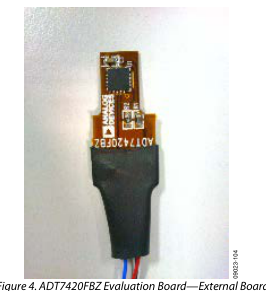
The ADT7x20FBZ flex boards are optional extras to the evaluation kit, which can be used as an extension to the ADT7x20 evaluation board or as standalone devices for interfacing with a microcontroller or FPGA. The evaluation kit allows the user to evaluate the performance of the ADT7320 and ADT7420 temperature sensors using a PC. The kit consists of two boards; a main board connected to the PC through the USB port and an external board. The external board and flex board are attached to the main board using wires that can withstand high temperatures, and can be used for remote temperature measurements in oil baths or ovens where the temperature exceeds the specifications of the USB cable.
The evaluation software allows the user to select the main board or the external board, as well as the desired temperature sensor device. When using the ADT7x20 evaluation board, in addition to this user guide, the user should also consult the ADT7320 and ADT7420 data sheets (available at the Analog Devices, Inc., website, www.analog.com).
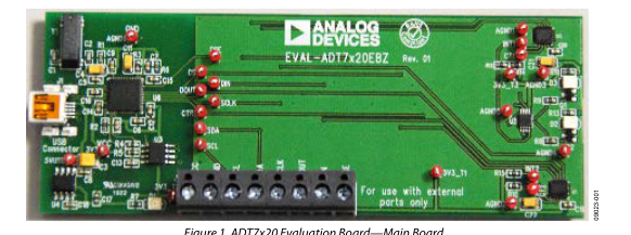
Figure 1. ADT7x20 Evaluation Board—Main Board
PLEASE SEE THE LAST PAGE FOR AN IMPORTANT
Rev. A | Page 1 of 16
WARNING AND LEGAL TERMS AND CONDITIONS.
Page 2
TABLE OF CONTENTS
Features .............................................................................................. 1 Evaluation Kit Contents ................................................................... 1 Optional Equipment ......................................................................... 1 General Description ......................................................................... 1 Revision History ............................................................................... 2 External Board Photographs ........................................................... 3 Evaluation Board Software .............................................................. 4
Software Installation .................................................................... 4 Using the ADT7x20 Evaluation Software ................................. 4
REVISION HISTORY
8/13—Rev. 0 to Rev. A Added Optional ADT7320FBZ and ADT7420FBZ Flex Boards .......................................................................... Universal 12/12—Revision 0: Initial Version
Device Selection ............................................................................4 Board Selection ..............................................................................4 Device Evaluation Software .........................................................5 Wiring Guidelines .............................................................................8 Evaluation Board Schematics and Artwork ...................................9 Ordering Information .................................................................... 15 Bill of Materials ........................................................................... 15 Related Links ................................................................................... 16
Rev. A | Page 2 of 16
Page 3
EXTERNAL BOARD PHOTOGRAPHS
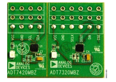
Figure 2. ADT7x20 Evaluation Board—External Board
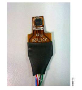
Figure 3. ADT7320FBZ Evaluation Board—External Board
Rev. A | Page 3 of 16
Page 4
EVALUATION BOARD SOFTWARE
SOFTWARE INSTALLATION
The ADT7x20 evaluation kit includes the evaluation software on a CD-ROM. The software is compatible with Windows® 2000/XP, Vista, and Windows 7. The evaluation software must be installed before connecting the evaluation board to the USB port of the PC to ensure that Windows recognizes it and to ensure that the driver is installed correctly. To install the software, run the ADT7x20 Evaluation Software Install.exe file from the CD-ROM. After the installation has completed, connect the ADT7x20 evaluation board to the PC USB port using the cable supplied. When the evaluation board is detected by the operating system, proceed through any dialog boxes that appear to finalize the
installation.
USING THE ADT7x20 EVALUATION SOFTWARE
During installation, a shortcut to the evaluation software is installed in the Start menu. From the Start menu, select All Programs, then Analog Devices, and click ADT7x20 Evaluation Software. You can launch the software using either this shortcut or by running the ADT7x20 Evaluation Software.exe file from the installation directory.
DEVICE SELECTION
When the evaluation software is launched, a window appears prompting you to select the desired device, as shown in Figure 5.
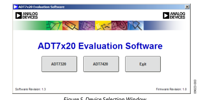
Figure 5. Device Selection Window
The ADT7320 uses the SPI interface whereas the ADT7420 uses the I2C. Other than the control interface, the two devices are identical in performance.
BOARD SELECTION
The device selected at the previous step in the Device Selection section can be located either on the main board or on the external board. After the desired device is selected, a window appears prompting you to select the location of the device (see Figure 6).
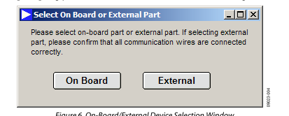
Figure 6. On-Board/External Device Selection Window
Rev. A | Page 4 of 16
Page 5
DEVICE EVALUATION SOFTWARE
After you complete the device and board selections, the evaluation software loads, allowing full control over the selected device. The software layout is the same for both the ADT7320 and ADT7420. There are three tabs in the evaluation software:
- Configuration Register
- Temperature Monitor
- ADT7x20 Registers The evaluation software also has Easy Setup and Close options.
Configuration Register This tab allows you full control over the configuration register of the selected device, as shown in Figure 7. At startup, the evaluation software initializes the configuration register to the default value of 0x90 (hexadecimal). For more details on how to set the configuration register, consult the device data sheet.
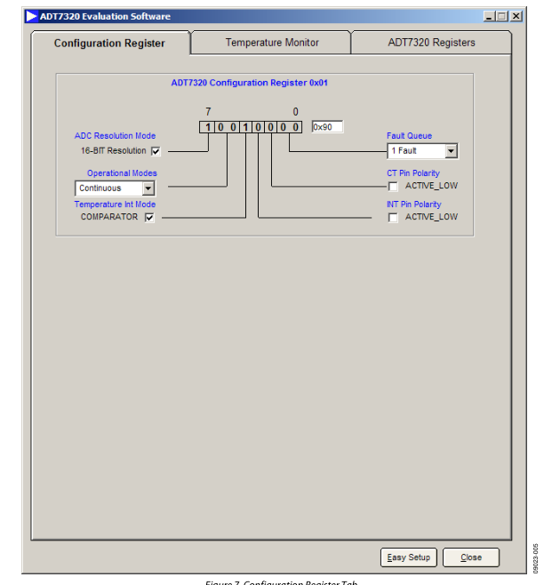
Figure 7. Configuration Register Tab
Rev. A | Page 5 of 16
Page 6
Temperature Monitor This tab displays the temperature reading from the selected device as well as the status of the alarms. This tab includes five control options (see Figure 8):
- Temperature Threshold
- Temperature Value
- Set Temperature Limits
- Log Data
- Temperature Values Temperature Threshold If the temperature goes above or below the high and low limits defined in the Set Temperature Limits section or above the critical threshold, the Temperature High Limit Threshold, Temperature Low Limit Threshold, and Temperature Critical Threshold indicators appear green.
Temperature Value This displays the actual ADC temperature in twos complement and degrees Celsius respectively. Set Temperature Limits This section allows you to update the high, low, critical, and hysteresis limits. These ADC values are loaded into the device. Because the conversion format is twos complement, any value over 4095 is a negative number. To change the value, you can use the arrow keys or type a number in the box to update the limits. The graph labeled Temperature Conversion Measurement displays the variation in time of the high and low temperature limits as well as the current temperature in twos complement format. At startup, the evaluation software initializes the tempera-
ture limits registers (THIGH, TLOW, TCRIT, and THYST) to the default values shown in Figure 6.
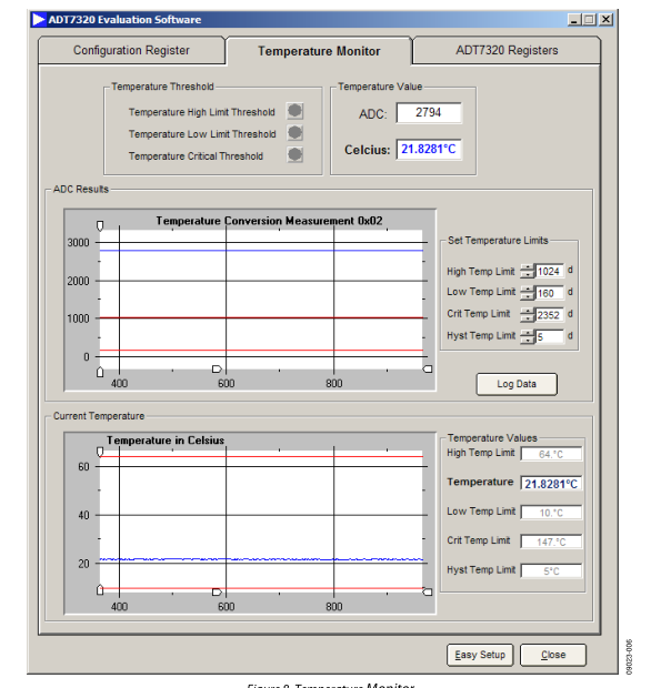
Figure 8. Temperature Monitor
Rev. A | Page 6 of 16
Page 7
Log Data The software can save the acquired data into an Excel or text file by clicking the Log Data button, which opens the dialog box shown in Figure 7 From this window, you can choose to log the ADC, the Celsius value, or both, as well as set the logging interval (see Figure 7).
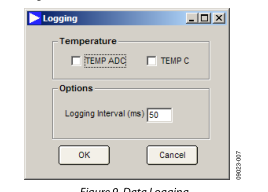
Figure 9. Data Logging
Temperature Values This section gives you an update of all the temperature limits and the temperature reading of the part. These values are a replica of the ADC values in the Set Temperature Limits section, converted into degrees Celsius. The graph labeled Temperature in Celsius displays the variation in time of the high and low temperature limits as well as the current temperature in degrees Celsius. Register Map This section displays all the register values for the part. You can read or write to any register by using the Read and Write buttons (see Figure 8). Easy Setup The Easy Setup button restores all registers with default values. Close This button closes the current window and returns to the
selection window (see Figure 3).
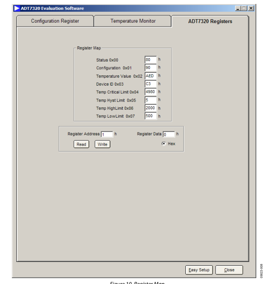
Figure 10. Register Map
Rev. A | Page 7 of 16
Page 8
WIRING GUIDELINES
Table 1 is a wiring guide for the ADT7320FBZ and Table 2 is a wiring guide for the ADT7420FBZ.
Table 2. ADT7420FBZ Wiring Guide
Table 1. ADT7320FBZ Wiring Guide
| Color | Reference Designator |
| Red Black White Blue Green Yellow | VCC Ground SCLK DOUT DIN CS |
| Color | Reference Designator |
| Red | VCC |
| Black | Ground |
| White | SCLK |
| Blue | DOUT |
| Green | DIN |
| Yellow | CS |
Rev. A | Page 8 of 16
Page 9
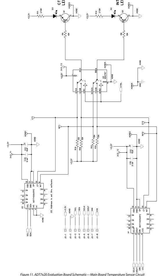
EVALUATION BOARD SCHEMATICS AND ARTWORK
09023-009
Rev. A | Page 9 of 16
Page 10
09023-010
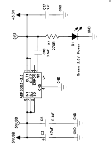
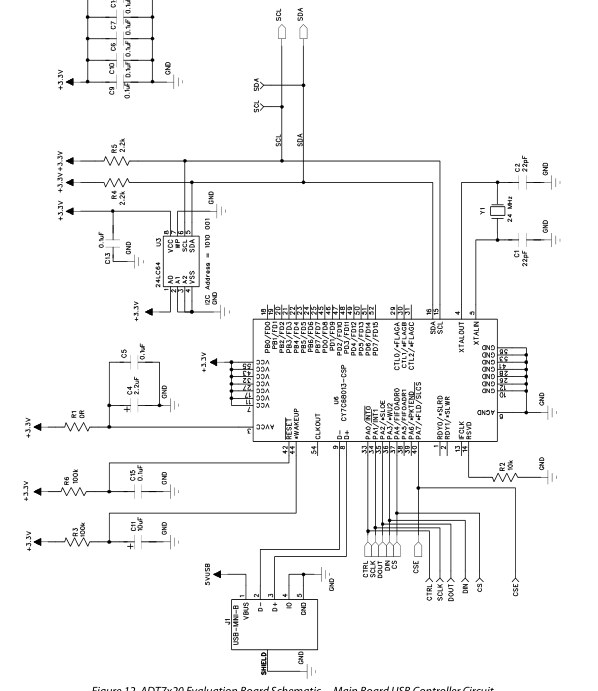
Figure 12. ADT7x20 Evaluation Board Schematic—Main Board USB Controller Circuit
Rev. A | Page 10 of 16
Page 11
09023-011
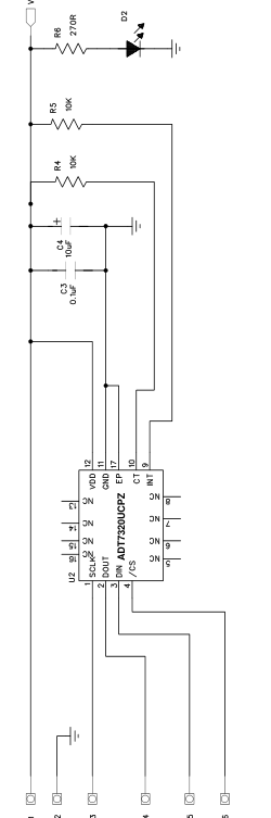
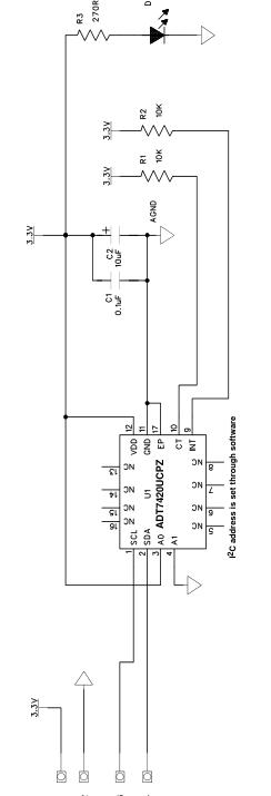
Figure 13. ADT7x20 Evaluation Board Schematic—External Board Circuit
Rev. A | Page 11 of 16
Page 12
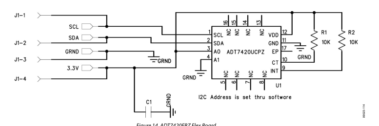
Figure 14. ADT7420FBZ Flex Board
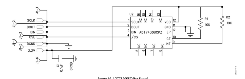
Figure 15. ADT7320FBZ Flex Board
Rev. A | Page 12 of 16
Page 13
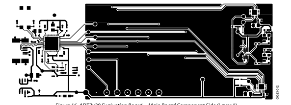
Figure 16. ADT7x20 Evaluation Board—Main Board Component Side (Layer 1)
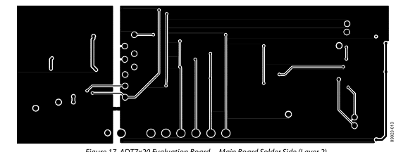
Figure 17. ADT7x20 Evaluation Board—Main Board Solder Side (Layer 2)
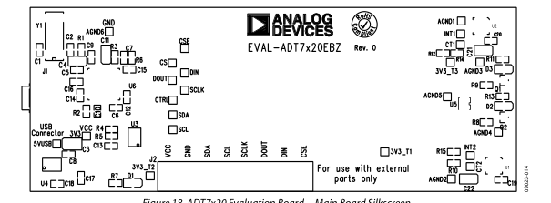
Figure 18. ADT7x20 Evaluation Board—Main Board Silkscreen
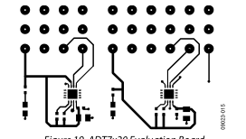
Figure 19. ADT7x20 Evaluation Board External Board Component Side (Layer 1)
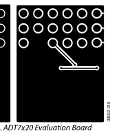
Figure 20. ADT7x20 Evaluation Board External Board Solder Side (Layer 2)
Rev. A | Page 13 of 16
Page 14
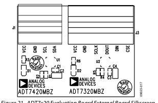
Figure 21. ADT7x20 Evaluation Board External Board Silkscreen
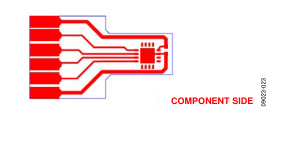
Figure 22. ADT7320FBZ Component Side (Layer1)
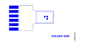
Figure 23. ADT7320FBZ Solder Side (Layer 2)
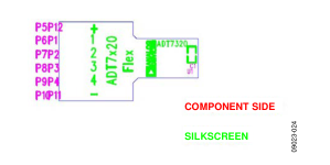
Figure 24. ADT7320FBZ Silkscreen
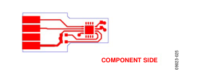
Figure 25. ADT7320FBZ Component Side(Layer1)
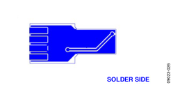
Figure 26. ADT7320FBZ Solder Side(Layer 2)
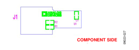
Figure 27. ADT7320FBZ Silkscreen
Rev. A | Page 14 of 16
Page 15
ORDERING INFORMATION
BILL OF MATERIALS
Table 3.Component Listing—Main Board
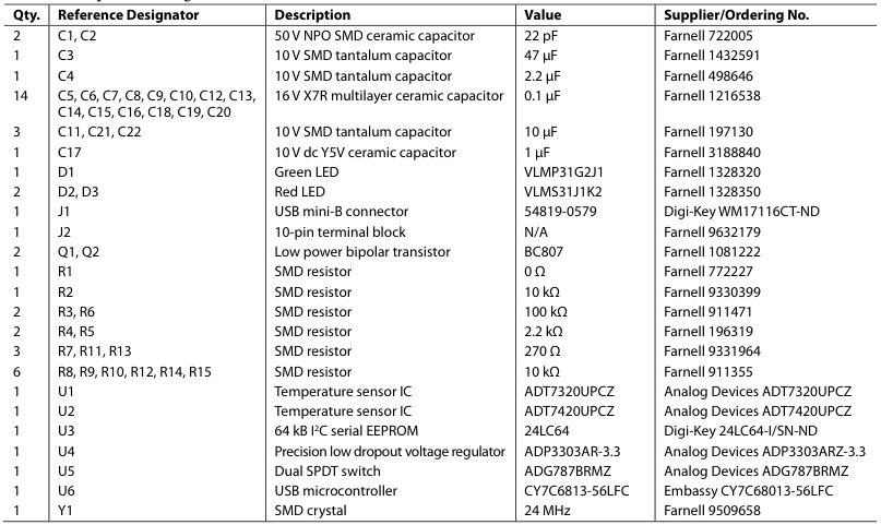
Table 4. Component Listing—External Board

Table 3. Component Listing—ADT7320FBZ Flexi Board

Table 4. Component Listing—ADT7420FBZ Flexi Board

Rev. A | Page 15 of 16
Page 16
RELATED LINKS
| Resource | Description |
|---|---|
| ADT7320 ADT7420 | Product Page, ±0.25°C Accurate, 16-Bit Digital SPI Temperature Sensor Product Page, ±0.25°C Accurate, 16-Bit Digital I2C Temperature Sensor |
I2C refers to a communications protocol originally developed by Philips Semiconductors (now NXP Semiconductors).
ESD Caution ESD (electrostatic discharge) sensitive device. Charged devices and circuit boards can discharge without detection. Although this product features patented or proprietary protection circuitry, damage may occur on devices subjected to high energy ESD. Therefore, proper ESD precautions should be taken to avoid performance degradation or loss of functionality. Legal Terms and Conditions By using the evaluation board discussed herein (together with any tools, components documentation or support materials, the “Evaluation Board”), you are agreeing to be bound by the terms and conditions set forth below (“Agreement”) unless you have purchased the Evaluation Board, in which case the Analog Devices Standard Terms and Conditions of Sale shall govern. Do not use the Evaluation Board until you
have read and agreed to the Agreement. Your use of the Evaluation Board shall signify your acceptance of the Agreement. This Agreement is made by and between you (“Customer”) and Analog Devices, Inc. (“ADI”), with its principal place of business at One Technology Way, Norwood, MA 02062, USA. Subject to the terms and conditions of the Agreement, ADI hereby grants to Customer a free, limited, personal, temporary, non-exclusive, non-sublicensable, non-transferable license to use the Evaluation Board FOR EVALUATION PURPOSES ONLY. Customer understands and agrees that the Evaluation Board is provided for the sole and exclusive purpose referenced above, and agrees not to use the Evaluation Board for any other purpose. Furthermore, the license granted is expressly made subject to the following additional
limitations: Customer shall not (i) rent, lease, display, sell, transfer, assign, sublicense, or distribute the Evaluation Board; and (ii) permit any Third Party to access the Evaluation Board. As used herein, the term “Third Party” includes any entity other than ADI, Customer, their employees, affiliates and in-house consultants. The Evaluation Board is NOT sold to Customer; all rights not expressly granted herein, including ownership of the Evaluation Board, are reserved by ADI. CONFIDENTIALITY. This Agreement and the Evaluation Board shall all be considered the confidential and proprietary information of ADI. Customer may not disclose or transfer any portion of the Evaluation Board to any other party for any reason. Upon discontinuation of use of the Evaluation Board or termination of this Agreement, Customer agrees to
promptly return the Evaluation Board to ADI. ADDITIONAL RESTRICTIONS. Customer may not disassemble, decompile or reverse engineer chips on the Evaluation Board. Customer shall inform ADI of any occurred damages or any modifications or alterations it makes to the Evaluation Board, including but not limited to soldering or any other activity that affects the material content of the Evaluation Board. Modifications to the Evaluation Board must comply with applicable law, including but not limited to the RoHS Directive. TERMINATION. ADI may terminate this Agreement at any time upon giving written notice to Customer. Customer agrees to return to ADI the Evaluation Board at that time. LIMITATION OF LIABILITY. THE EVALUATION BOARD PROVIDED HEREUNDER IS PROVIDED “AS IS” AND ADI MAKES NO
WARRANTIES OR REPRESENTATIONS OF ANY KIND WITH RESPECT TO IT. ADI SPECIFICALLY DISCLAIMS ANY REPRESENTATIONS, ENDORSEMENTS, GUARANTEES, OR WARRANTIES, EXPRESS OR IMPLIED, RELATED TO THE EVALUATION BOARD INCLUDING, BUT NOT LIMITED TO, THE IMPLIED WARRANTY OF MERCHANTABILITY, TITLE, FITNESS FOR A PARTICULAR PURPOSE OR NONINFRINGEMENT OF INTELLECTUAL PROPERTY RIGHTS. IN NO EVENT WILL ADI AND ITS LICENSORS BE LIABLE FOR ANY INCIDENTAL, SPECIAL, INDIRECT, OR CONSEQUENTIAL DAMAGES RESULTING FROM CUSTOMER’S POSSESSION OR USE OF THE EVALUATION BOARD, INCLUDING BUT NOT LIMITED TO LOST PROFITS, DELAY COSTS, LABOR COSTS OR LOSS OF GOODWILL. ADI’S TOTAL LIABILITY FROM ANY AND ALL CAUSES SHALL BE LIMITED TO THE
AMOUNT OF ONE HUNDRED US DOLLARS ($100.00). EXPORT. Customer agrees that it will not directly or indirectly export the Evaluation Board to another country, and that it will comply with all applicable United States federal laws and regulations relating to exports. GOVERNING LAW. This Agreement shall be governed by and construed in accordance with the substantive laws of the Commonwealth of Massachusetts (excluding conflict of law rules). Any legal action regarding this Agreement will be heard in the state or federal courts having jurisdiction in Suffolk County, Massachusetts, and Customer hereby submits to the personal jurisdiction and venue of such courts. The United Nations Convention on Contracts for the International Sale of Goods shall not apply to this Agreement and is expressly disclaimed.
©2013 Analog Devices, Inc. All rights reserved. Trademarks and registered trademarks are the property of their respective owners.
UG09023-0-8/13(A)