

 Download PDF
19280 DESCO
Document overview
- PDF pages: 7
Technical content
Page 1
TECHNICAL BULLETIN TB-3069
Combo Tester Installation, Operation and Maintenance
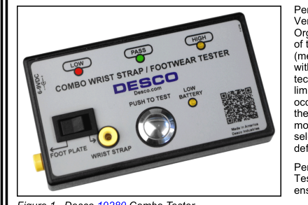
Figure 1. Desco 19280 Combo Tester
Description
The Desco Combo Tester verifies the functionality of an operator’s wrist strap and footwear (footwear test requires foot plate). It determines if an operator’s wrist strap and footwear will function correctly. A rocker switch allows the operator to select a wrist strap or footwear test. A green light indicates that the wrist strap or footwear is passing. Red and yellow lights plus an audible alarm indicate when the wrist strap or footwear is failing. If failure occurs, the tester will also display if the grounding device’s resistance is too low or too high.
The Combo Tester may also be used to test smocks or garments that feature a grounding mechanism for operators using a coiled cord connection.
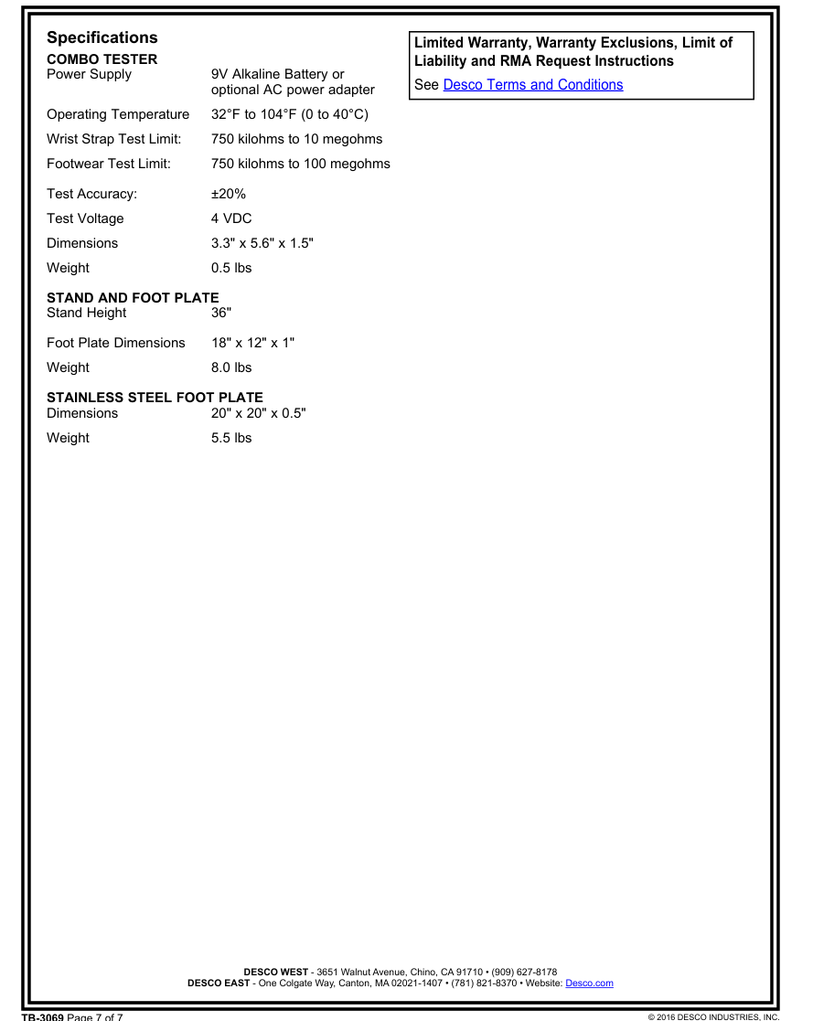
The factory test limits are set to:
Wrist Straps: 750 kilohms and 10 megohms Footwear:
750 kilohms and 100 megohms
Limits meet the required limits for Compliance Verification of ANSI/ESD S20.20 (Wrist Strap System < 3.5 x 10⁷ ohms and Footwear < 1 x 10⁹ ohms tested per ESD TR53).
Contact Desco Customer Service if custom test limits are required.
The Combo Tester can be powered by a 9 volt battery or the Desco 98256 (120VAC) and 98257 (220VAC) power adapters (sold separately). A warning light on the tester indicates when the battery power is too low and affecting the test results.
Each Combo Tester is calibrated with accepted procedures and standards traceable to the National Institute of Standards and Technology (NIST) and includes a NIST certificate.
TB-3069 Page 1 of 7 September 2016
Made in the United States of America
Per ANSI/ESD S20.20 section 7.4 “A Compliance Verification Plan shall be established to ensure the Organization’s fulfillment of the technical requirements of the ESD Control Program Plan. Process monitoring (measurements) shall be conducted in accordance with a Compliance Verification Plan that identifies the technical requirements to be verified, the measurement limits and the frequency at which those verifications shall occur. The Compliance Verification Plan shall document the test methods and equipment used for process monitoring and measurements. … The test equipment selected shall be capable of making the measurements defined in the Compliance Verification Plan.”
Per ANSI/ESD S1.1 Annex A.3 Frequency of System Testing “The wrist strap system should be tested daily to ensure proper electrical resistance.”
Per ESD Handbook ESD TR20.20 section 5.3.2.4.2 Additional User Wrist Strap Testing “Proper testing of the wrist strap includes the resistance of the groundable point on the end of the cord, the cord itself, the resistor, the cord-to-cuff snap connector, the resistance of the interface of the cuff, the cuff/wrist interface, and the resistance of the person between the wrist and the hand that contacts the test electrode.”
Per ESD Handbook ESD TR20.20 section 5.3.2.2.2 Wrist Strap Ground Cord “At first glance, the ground cord appears to be a relatively simple assembly. However, the design requirements are considerable, given the wide range of user applications and the durability requirements of constant tugging, flexing, and dragging over the edge of workstation tops and equipment chassis.”
| Item | Description |
|---|---|
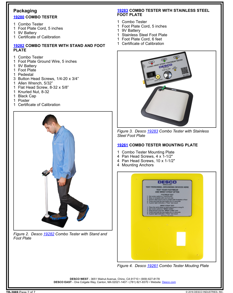
| 19280 | Combo Tester |
| 19282 | Combo Tester with Stand and Foot Plate |
| 19283 | Combo Tester with Stainless Steel Foot Plate |
| 19261 | Combo Tester Mounting Plate |
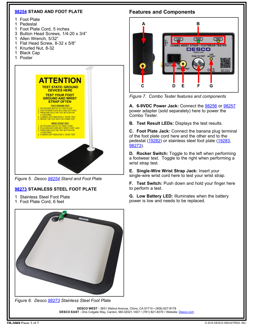
| 98254 | Stand and Foot Plate |
| 98273 | Stainless Steel Foot Plate |
| 98256* | Power Adapter, 120VAC Input, 6VDC Output |
| 98257* | Power Adapter, 220VAC Input, 9VDC Output |
\*Use only the Desco 98256 and 98257 power adapters with the Combo Tester. Using any other power adapter may damage the unit and void the warranty.
Page 2
TB-3069 Page 2 of 7
Page 3
TB-3069 Page 3 of 7
Page 4
Installation
The Combo Tester is portable when powered by a 9V alkaline battery, but it also has the flexibility of being permanently installed at a location. Use the three keyhole slots located on the back of the Combo Tester to mount it to a wall or stand.
INSTALLING THE 19280 / 19283 COMBO TESTER
- Install the 9V alkaline battery into the Combo Tester.
- Select a location to mount the Combo Tester.
- Install three #6 or #8 screws into a wall or other vertical surface as shown in the figure below. Make sure that the screw heads do not project out more than 1/4" from mounting surface.
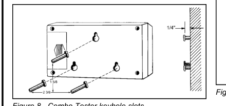
Figure 8. Combo Tester keyhole slots
- Mount the Combo Tester onto the screws, and pull it down to secure it into place.
- Set the Stainless Steel Foot Plate below the tester (if applicable).
- Insert the 6' long foot plate cord’s banana plug into the Combo Tester’s foot plate jack.
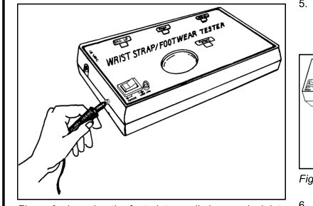
Figure 9. Inserting the foot plate cord’s banana jack into the Combo Tester
- Snap the opposite end of the foot plate cord onto the Stainless Steel Foot Plate.
TB-3069 Page 4 of 7
INSTALLING THE 19282 COMBO TESTER WITH
STAND AND FOOT PLATE
- Position the pedestal on top of the foot plate with the mounting bracket sloping toward the operator. Secure the pedestal to the foot plate using the 3 included button head screws and allen wrench.
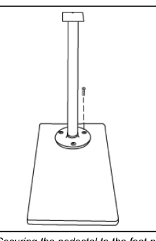
Figure 10. Securing the pedestal to the foot plate
- Install the 9V alkaline battery into the Combo Tester.
- Mount the Combo Tester onto the pedestal’s mounting bracket and flat head screw, and screw down to secure it into place.
- Insert the 5" long foot plate cord’s banana plug into the Combo Tester’s foot plate jack.
- Attach the foot plate cord’s ring terminal to the flat head screw located at the back of the pedestal’s mounting bracket, and tighten the knurled nut to secure.
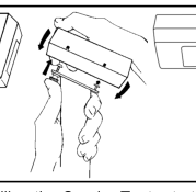
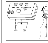
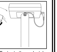
Figure 11. Installing the Combo Tester to the pedestal
- Cover the knurled nut and flat head screw with included insulative vinyl cap.
- Install the included poster at eye level nearby the test station.
Page 5
TB-3069 Page 5 of 7
Page 6
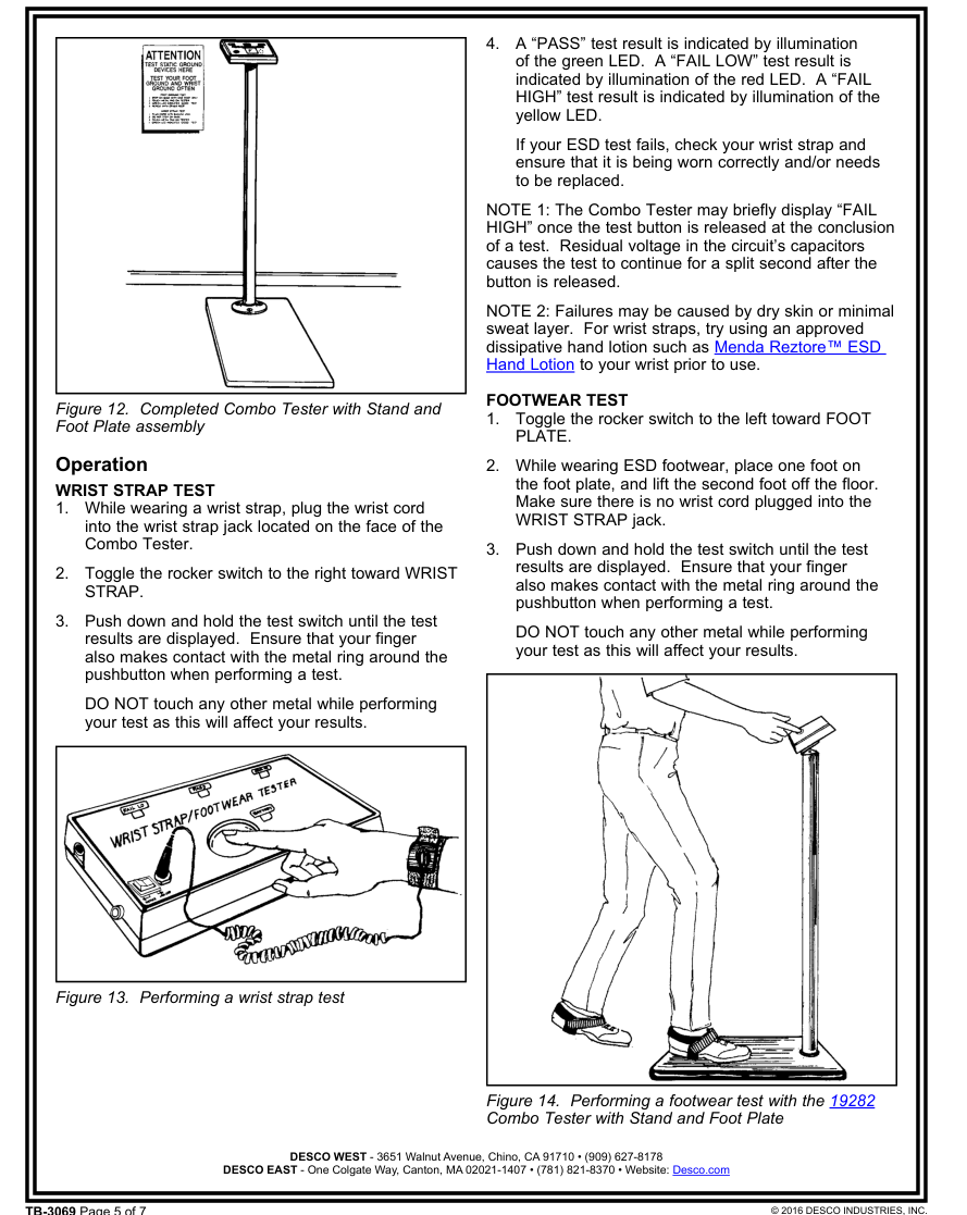
- A “PASS” test result is indicated by illumination of the green LED. A “FAIL LOW” test result is indicated by illumination of the red LED. A “FAIL HIGH” test result is indicated by illumination of the yellow LED.
If your ESD test fails, check your footwear and ensure that it is being worn correctly and/or needs to be replaced.
NOTE 1: The Combo Tester may briefly display “FAIL HIGH” once the test button is released at the conclusion of a test. Residual voltage in the circuit’s capacitors causes the test to continue for a split second after the button is released.
NOTE 2: Failures may be caused by dry skin or minimal sweat layer. Footwear test results can be improved by taking a short walk to build a sweat layer for better conductivity.
- Repeat steps 2-4 for the second foot.
Maintenance
The Combo Tester requires little maintenance. There are no user serviceable parts. If your meter requires service beyond cleaning the test switch or foot plate, please contact the factory.
Use a minimum of 80% isopropyl alcohol to clean the test switch. Other cleaners are susceptible to leaving residue.
BATTERY REPLACMENT
The low battery indicator flashes briefly every time the unit is used. Replace the battery once the indicator becomes constant during testing. Open the compartment located on the back of the tester to replace the battery. The tester uses one 9V alkaline battery.
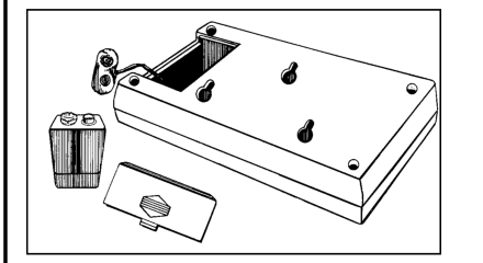
Figure 15. Replacing the battery
TB-3069 Page 6 of 7
Calibration
The Desco Combo Tester is calibrated to NIST traceable standards. There are no user adjustments necessary. We recommend that calibration be performed annually using the Desco 07010 Calibration Unit. It is a convenient product which allows the customer to perform NIST traceable calibration on single-wire personnel testers. The 07010 is designed to be used on the shop floor at the workstation, virtually eliminating downtime, verifying that the tester is operating within tolerances.
View technical bulletin TB-2039 for more information on the 07010 Calibration Unit and instructions to calibrate the Combo Tester.
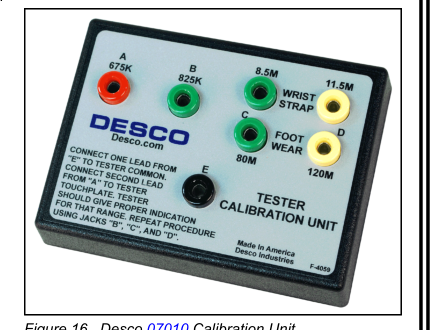
Figure 16. Desco 07010 Calibration Unit
Page 7
TB-3069 Page 7 of 7