

 Download PDF
DATASHEET SEARCH SITE
Document overview
- PDF pages: 5
Technical content
Page 1
General Specifications
GENERAL DESCRIPTION
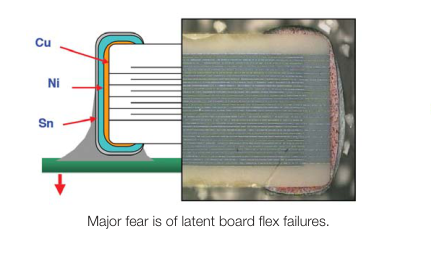
With increased requirements from the automotive industry for additional component robustness, AVX recognized the need to produce a MLCC with enhanced mechanical strength. It was noted that many components may be subject to severe flexing and vibration when used in various under the hood automotive and other harsh environment applications. To satisfy the requirement for enhanced mechanical strength, AVX had to find a way of ensuring electrical integrity is maintained whilst external forces are being applied to the component. It was found that the structure of the termination needed to be flexible and after much research and development, AVX launched FLEXITERM®. FLEXITERM® is designed to enhance the
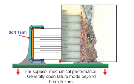
mechanical flexure and temperature cycling performance of a standard ceramic capacitor with an X7R dielectric. The industry standard for flexure is 2mm minimum. Using FLEXITERM®, AVX provides up to 5mm of flexure without internal cracks. Beyond 5mm, the capacitor will generally fail “open”. As well as for automotive applications FLEXITERM® will provide Design Engineers with a satisfactory solution when designing PCB’s which may be subject to high levels of board flexure.
PRODUCT ADVANTAGES
- High mechanical performance able to withstand, 5mm bend test guaranteed.
- Increased temperature cycling performance, 3000 cycles and beyond.
- Flexible termination system.
- Reduction in circuit board flex failures.
- Base metal electrode system.
- Automotive or commercial grade products available.
HOW TO ORDER
0805
5 C
104
K
A
Style Voltage Dielectric
Capacitance
Capacitance
Failure
Code (In pF)
Tolerance
Rate
0603 6 = 6.3V
C = X7R 2 Sig Digits +
J = ±5%\*
A=Commercial
0805 Z = 10V
F = X8R Number of Zeros
K = ±10%
4 = Automotive
1206 Y = 16V
e.g., 104 = 100nF
M = ±20%
1210 3 = 25V 1812 5 = 50V
\*≤1μF only
2220 1 = 100V 2 = 200V
NOTE: Contact factory for availability of Tolerance Options for Specific Part Numbers.
APPLICATIONS
High Flexure Stress Circuit Boards
- e.g. Depanelization: Components near edges of board.
Variable Temperature Applications
- Soft termination offers improved reliability per- formance in applications where there is tem- perature variation.
- e.g. All kind of engine sensors: Direct connection to battery rail.
Automotive Applications
- Improved reliability.
- Excellent mechanical performance and thermo mechanical performance.
2
A
Z
Terminations Packaging
Special Code A = Std. Product
Z = FLEXITERM® 2 = 7" reel
4 = 13" reel
For FLEXITERM® with Tin/Lead termination see AVX LD Series
Page 2
Specifications and Test Methods
PERFORMANCE TESTING
AEC-Q200 Qualification:
- Created by the Automotive Electronics
Council
- Specification defining stress test qualification for passive components
Testing: Key tests used to compare soft termination to AEC-Q200 qualification:
- Bend Test
- Temperature Cycle Test
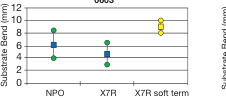
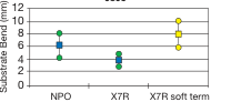
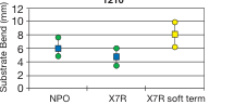
BOARD BEND TEST RESULTS
AEC-Q200 Vrs AVX FLEXITERM® Bend Test
0603
0805
BOARD BEND TEST PROCEDURE
According to AEC-Q200
Test Procedure as per AEC-Q200: Sample size:
20 components
Span: 90mm
Minimum deflection spec: 2 mm
LOADING KNIFE
- Components soldered onto FR4 PCB (Figure 1)
MOUNTING
- Board connected electrically to the test equipment
ASSEMBLY
(Figure 2)
DIGITAL CALIPER
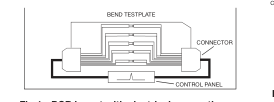
CONTROL PANEL
Fig 2 - Board Bend test
Fig 1 - PCB layout with electrical connections
equipment
AVX ENHANCED SOFT
TERMINATION BEND TEST PROCEDURE
Bend Test The capacitor is soldered to the printed circuit
1210
board as shown and is bent up to 10mm at
1206
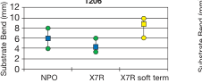
TABLE SUMMARY
Typical bend test results are shown below: Style Conventional Termination
FLEXITERM®
0603 >2mm
5mm
0805 >2mm
5mm
1206 >2mm
5mm
TEMPERATURE CYCLE TEST PROCEDURE
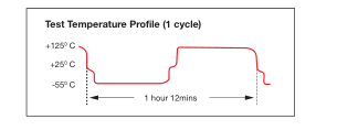
Test Procedure as per AEC-Q200: The test is conducted to determine the resistance of the component when it is exposed to extremes of alternating high and low temperatures.
- Sample lot size quantity 77 pieces
- TC chamber cycle from -55ºC to +125ºC for 1000 cycles
- Interim electrical measurements at 250, 500, 1000 cycles
- Measure parameter capacitance dissipation factor, insulation resistance
1mm per second:
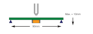
- The board is placed on 2 supports 90mm apart (capacitor side down)
- The row of capacitors is aligned with the load stressing knife
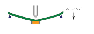
- The load is applied and the deflection where the part starts to crack is recorded (Note: Equipment detects the start of the crack using a highly sensitive current detection circuit)
- The maximum deflection capability is 10mm
Page 3
Specifications and Test Methods
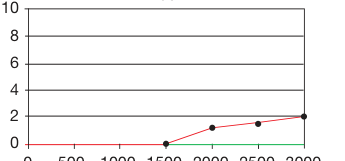
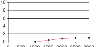
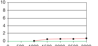
BEYOND 1000 CYCLES: TEMPERATURE CYCLE TEST RESULTS
0603
0 500 1000 1500 2000 2500 3000
1206
0 500 1000 1500 2000 2500 3000
0805
0 500
1000 1500 2000 2500 3000
1210
0 500
1000 1500 2000 2500 3000
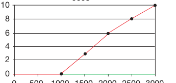
AEC-Q200 specification states
Soft Term - No Defects up to 3000 cycles
1000 cycles compared to AVX 3000 temperature cycles.
FLEXITERM® TEST SUMMARY
- Qualified to AEC-Q200 test/specification with the exception • Board bend test improvement by a factor of 2 to 4 times. of using AVX 3000 temperature cycles (up to +150°C bend test guaranteed greater than 5mm).
- FLEXITERM® provides improved performance compared to standard termination systems.
WITHOUT SOFT TERMINATION
- Temperature Cycling: – 0% Failure up to 3000 cycles – No ESR change up to 3000 cycles
WITH SOFT TERMINATION
Page 4
X8R Dielectric Capacitance Range
| SIZE | 0603 | 0805 | 1206 | ||||
| WVDC | 25V | 50V | 25V | 50V | 25V | 50V | |
| 271 | Cap 270 | G | G | ||||
| 331 | (pF) 330 | G | G | J | J | ||
| 471 | 470 | G | G | J | J | ||
| 681 | 680 | G | G | J | J | ||
| 102 | 1000 | G | G | J | J | J | J |
| 152 | 1500 | G | G | J | J | J | J |
| 182 | 1800 | G | G | J | J | J | J |
| 222 | 2200 | G | G | J | J | J | J |
| 272 | 2700 | G | G | J | J | J | J |
| 332 | 3300 | G | G | J | J | J | J |
| 392 | 3900 | G | G | J | J | J | J |
| 472 | 4700 | G | G | J | J | J | J |
| 562 | 5600 | G | G | J | J | J | J |
| 682 | 6800 | G | G | J | J | J | J |
| 822 | 8200 | G | G | J | J | J | J |
| 103 | Cap 0.01 | G | G | J | J | J | J |
| 123 | (μF) 0.012 | G | G | J | J | J | J |
| 153 | 0.015 | G | G | J | J | J | J |
| 183 | 0.018 | G | G | J | J | J | J |
| 223 | 0.022 | G | G | J | J | J | J |
| 273 | 0.027 | G | G | J | J | J | J |
| 333 | 0.033 | G | G | J | J | J | J |
| 393 | 0.039 | G | G | J | J | J | J |
| 473 | 0.047 | G | G | J | J | J | J |
| 563 | 0.056 | G | N | N | M | M | |
| 683 | 0.068 | G | N | N | M | M | |
| 823 | 0.082 | N | N | M | M | ||
| 104 | 0.1 | N | N | M | M | ||
| 124 | 0.12 | N | N | M | M | ||
| 154 | 0.15 | N | N | M | M | ||
| 184 | 0.18 | N | M | M | |||
| 224 | 0.22 | N | M | M | |||
| 274 | 0.27 | M | M | ||||
| 334 | 0.33 | M | M | ||||
| 394 | 0.39 | M | |||||
| 474 | 0.47 | M | |||||
| 684 | 0.68 | ||||||
| 824 | 0.82 | ||||||
| 105 | 1 | ||||||
| WVDC | 25V | 50V | 25V | 50V | 25V | 50V | |
| SIZE | 0603 | 0805 | 1206 | ||||
| Letter | A | C | E | G | J | K | M | N | P | Q | X | Y | Z |
| Max. Thickness | 0.33 (0.013) | 0.56 (0.022) | 0.71 (0.028) | 0.90 (0.035) | 0.94 (0.037) | 1.02 (0.040) | 1.27 (0.050) | 1.40 (0.055) | 1.52 (0.060) | 1.78 (0.070) | 2.29 (0.090) | 2.54 (0.100) | 2.79 (0.110) |
| PAPER | EMBOSSED | ||||||||||||
= AEC-Q200 Qualified
Page 5
X7R Dielectric Capacitance Range
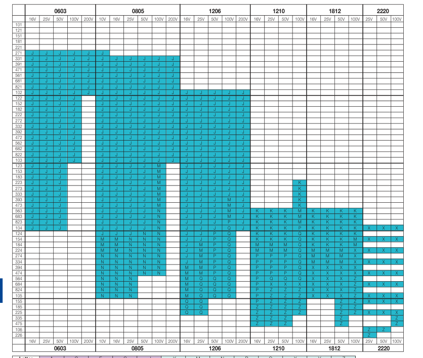
| Letter | A | C | E | G | J | K | M | N | P | Q | X | Y | Z |
| Max. Thickness | 0.33 (0.013) | 0.56 (0.022) | 0.71 (0.028) | 0.90 (0.035) | 0.94 (0.037) | 1.02 (0.040) | 1.27 (0.050) | 1.40 (0.055) | 1.52 (0.060) | 1.78 (0.070) | 2.29 (0.090) | 2.54 (0.100) | 2.79 (0.110) |
| PAPER | EMBOSSED | ||||||||||||