
DATASHEET SEARCH SITE
Document overview
- Manufacturer or author: Provided By digicamel.com
- PDF pages: 15
Technical content
© PHOENIX CONTACT 2019 PCB hybrid connector, Push-in spring connection Order No.: 1717003 Type: LPCH 6/ 5+4-STL5-7,62 Data sheet
1 Main features
2 Your advantages
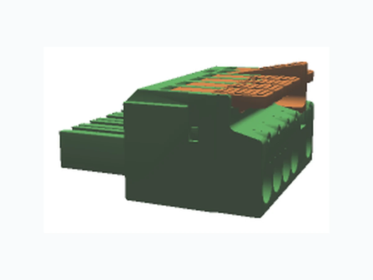
No. of pos. 9 Nominal current 41 A Conductor cross section 6 mm² Nominal voltage 1000 V Color green (6021) Connection direction 0 ° Pitch 7.62 mm Type of packaging packed in cardboard Connection method Push-in spring connection Tool-free lever principle enables time-saving connection and release of conductors with/without ferrules Clear lever positions provide reliable feedback on opened or closed clamping spaces Defined contact force ensures that contact remains stable over the long term Time-saving push-in connection when lever is closed Make sure you always use the latest documentation. It can be downloaded at: phoenixcontact.net/product/1717003 2019-03-15 Product version 00 Figure shows a 4+4-pos. version with locking flange at position 4 Document revision 00
1717003 LPCH 6/ 5+4-STL5-7,62
REF 1716970 PHOENIX CONTACT 2 / 15 © PHOENIX CONTACT 2019 2019-03-15 Product version 00 Document revision 00 3T a b l e o f c o n t e n t s
REF 1716970 PHOENIX CONTACT 3 / 15 © PHOENIX CONTACT 2019 2019-03-15 Product version 00 Document revision 00 4 3D model in PDF can be acti vated (Acrobat Reader only)
REF 1716970 PHOENIX CONTACT 4 / 15 © PHOENIX CONTACT 2019 2019-03-15 Product version 00 Document revision 00
5 General Technical Data
Order No. 1717003 Type LPCH 6/ 5+4-STL5-7,62 Plug-in system POWER COMBICON 6 Hybrid Product type PCB hybrid connector Type of contact Female connector Range of articles LPCH 6/..-STL Number of positions 9 Number of connections 9 Number of potentials 9 Type of locking Snap-in locking Self-locking flange Connection direction of the connector to the PCB 0 ° 5.1 item properties Power Signal Pitch 7.62 mm 3.81 mm Connection method Push-in spring connection Push-in spring connection Number of levels 1 2 Number of positions 5 4 Number of connections 5 4 Number of potentials 5 4 Power Signal Stripping length 18 mm 10 mm
5.2 Connection capacity
Connection data AWG Power Signal
5.3 Connection capacity AWG
REF 1716970 PHOENIX CONTACT 5 / 15 © PHOENIX CONTACT 2019 2019-03-15 Product version 00 Document revision 00
6 Material properties
Note WEEE/RoHS-compliant, free of whis kers according to IEC 60068-2-82/JEDEC JESD 201
6.1 RoHs/WEEE compliant
Contact material Cu alloy Cu alloy Terminal point surface Tin (4 - 8 µm Sn) Tin (4 - 8 µm Sn) Surface contact area Tin (4 - 8 µm Sn) Tin (4 - 8 µm Sn) Surface characteristics Tin-plated hot-dip tin-plated
6.2 Material of metal parts
Insulating material PA GF PA Insulating material group I I CTI according to IEC 60112 600 600 Flammability rating according to UL 94 V0 V0 Color green (6021) green (6021)
6.3 Material Kunststoffteile
Insulating material PA GF PBT Insulating material group I I CTI according to IEC 60112 600 600 Flammability rating according to UL 94 V0 V0 Color orange (2003) orange (2003)
6.4 Insulation material specifications for actuating element
REF 1716970 PHOENIX CONTACT 6 / 15 © PHOENIX CONTACT 2019 2019-03-15 Product version 00 Document revision 00 7D i m e n s i o n s Length 48 mm Width 55.54 mm Total height 35.65 mm Dimension a 38.1 mm
7.1 Dimensions for the product
REF 1716970 PHOENIX CONTACT 7 / 15 © PHOENIX CONTACT 2019 2019-03-15 Product version 00 Document revision 00 8S e r i e s d r a w i n g
REF 1716970 PHOENIX CONTACT 8 / 15 © PHOENIX CONTACT 2019 2019-03-15 Product version 00 Document revision 00 Type of packaging p acked in cardboard Pieces per package 25
9 Packaging information
Ambient temperature (storage/transport) -40 °C ... 70 °C Ambient temperature (assembly) -5 °C ... 100 °C Ambient temperature (operation) -40 °C (dependent on the derating curve)
10.1 Temperature limit values
REF 1716970 PHOENIX CONTACT 9 / 15 © PHOENIX CONTACT 2019 2019-03-15 Product version 00 Document revision 00
11 General tests
12 Mechanical tests
Brief description PCB hybrid connector
11.1 Specification
Specification IEC 60999-1:1999-11
12.1 Check for damage to conductor or loosening
Specification IEC 60999-1:1999-11 Result Test passed Conductor cross section/conductor type/tractive force actual value 0.75 mm² / solid / > 30 N Conductor cross section/conductor type/tractive force actual value 0.75 mm² / flexible / > 30 N Conductor cross section/conductor type/tractive force actual value 10 mm² / solid / > 90 N Conductor cross section/conductor type/tractive force actual value 6 mm² / flexible / > 80 N
12.2 Pull-out test
Specification IEC 60999-1:1999-11 Result Test passed
12.3 Repeated connection and disconnection
Specification IEC 60999-1:1999-11 Result Test passed
12.4 Conductor connection
Specification IEC 61984:2008-10 Visual examination Test passed Specification IEC 60512-1-1:2002-02 Dimensional test Test passed Specification IEC 60512-1-2:2002-02 Resistance of marking Test passed Specification IEC 60068-2-70:1995-12 Insertion and withdrawal force Test passed Specification IEC 60512-13-2:2006-02 No. of cycles 25 Insertion strength per pos. approx. 7 N Withdraw strength per pos. approx. 4 N
12.5 Mechanical test group A
REF 1716970 PHOENIX CONTACT 10 / 15 © PHOENIX CONTACT 2019 2019-03-15 Product version 00 Document revision 00 Polarization and coding Test passed Specification IEC 60512-13-5:2006-02 Test force 20 N Contact retention in insert Test passed Specification IEC 60512-15-1:2008-05 Test force per pos. 20 N
REF 1716970 PHOENIX CONTACT 11 / 15 © PHOENIX CONTACT 2019 2019-03-15 Product version 00 Document revision 00 Rated current / conductor cross section 41 A / 6 mm² Rated insulation voltage (III/2) 1000 V Rated surge voltage (III/2) 8 kV Contact resistance 0.42 mΩ Degree of pollution 2
13.1 Electrical data
Component PCB hybrid connector Specification IEC 60664-1:2007-04 Mains type unearthed mains Insulating material group I Comparative tracking index (IEC 60112:2003-01) CTI 600 Rated insulation voltage 800 V 1000 V 1000 V Rated surge voltage 8 kV 8 kV 6 kV Degree of pollution 3 2 2 Overvoltage category III III II Minimum clearance case A (inhomogeneous field) 8 mm 8 mm 5.5 mm Minimum value of the creepage path requirement in acc. with table 10 mm 5 mm 5 mm
13.2 Air and creepage distances
Specification IEC 60999-1:1999-11 Result Test passed Voltage drop Voltage drop (U) after the load ≤ 15 mV Conductor cross section, flexible 0.75 mm² ... 6 mm² Conductor cross section, solid 0.75 mm² ... 10 mm²
13.3 Electrical function
Specification IEC 60999-1:1999-11 Result Test passed Voltage drop Voltage drop (U) after the load ≤ 22.5 mV or 1.5 x U after 24 h The small value is to be used. Test current (minimum cross section) 9 A DC Test current (maximum cross section) 41 A DC Temperature cycles 192 Conductor cross section, flexible 0.75 mm² ... 6 mm² Conductor cross section, solid 0.75 mm² ... 10 mm²
13.4 Temperature cycles
REF 1716970 PHOENIX CONTACT 12 / 15 © PHOENIX CONTACT 2019 2019-03-15 Product version 00 Document revision 00
14 Current carrying capacity/derating curves
Specification IEC 61984:2008-10 Note Representation based on IEC 60512-5-2:2002-02 Reduction factor 0.8 Number of positions See diagram Conductor cross section 6 mm² 0 10 20 30 40 50 60 70 80 90 100 110 120130 = 4+4-pos. = 1000 h∑< Ambient temperature [°C] Current strength [A] Insulation resistance Specification IEC 60512-3-1:2002-02 Result Test passed Insulation resistance, neighboring positions > 5 M Ω
REF 1716970 PHOENIX CONTACT 13 / 15 © PHOENIX CONTACT 2019 2019-03-15 Product version 00 Document revision 00
15 Environmental and durability tests
Specification IEC 60068-2-6:2007-12 Result Test passed Frequency 10 - 150 - 10 Hz Sweep speed 1 octave/min Amplitude 0.35 mm (10 - 60.1 Hz) Acceleration 5 g (60.1 - 150 Hz) Test duration per axis 2.5 h Test directions X-, Y- and Z-axis Note The connected conductor loops were guided to the test sample at a distance of approx. 10 cm.
15.1 Vibration test
Specification IEC 60068-2-27:2008-02 Result Test passed Pulse shape Semi-sinusoidal Peak acceleration 30g Shock duration 18 ms Number of shocks per direction 3 Test directions X-, Y- and Z-axis (pos. and neg.) Specification IEC 61984:2008-10 Main features Connectors with out switching capacity (COC) Construction form Fixed connectors Strain relief elements w ithout strain relief Connection method Can be reconnected Protection against electric shock not encapsul ated - back of hand safety when plugged in Protective conductor without PE Lock no Connection method Screwless terminal points
16 Classification for connectors
Specification IEC 60512-3-1:2002-02 Result Test passed Insulation resistance, neighboring positions > 5 M Ω
16.1 Insulation resistance
17 Approvals
cULus Recognized Use group B1 F F1 mm²/AWG/kcmil 24-16 18-8 24-16 Voltage 150 V 600 V 160 V Current 6 A 35 A 6 A
REF 1716970 PHOENIX CONTACT 14 / 15 © PHOENIX CONTACT 2019 2019-03-15 Product version 00 Document revision 00
18 Commercial Data
Order No. 1717003 Type LPCH 6/ 5+4-STL5-7,62 Pieces per package 25 Net weight 22.22 g GTIN 4055626532585 Information that applies locally, see link on page 1 Country of origin Information that applies locally, see link on page 1 Description Order No. Type Coding profile, for plugging into the coding ribs of the plug at a later date, insulating material, color: Red
1701967 CP-PC RD
3200603 AI 6 -18 YE
Crimping pliers, for uninsulated and insulated ferrules, DIN 46228 Part 1 and 4, from 0.14 mm² 6 mm², also for TWIN ferrules up to 2 x 4 mm², au- tomatic cross section adjustment, lateral insertion, equipped with fall pro- tection
1213144 CRIMPFOX CENTRUS 6S
Stripping tool, for cables and conductors from 0.02 - 10 mm², self-adjus- ting, stripping length of up to 18 mm, cutting capacity of up to 10 mm² stran- ded/1.5 mm² solid, replaceable stripping blade
1212150 WIREFOX 10
19 Accessories
REF 1716970 PHOENIX CONTACT 15 / 15PHOENIX CONTACT GmbH & Co. KG • 32823 Blomberg • Germany phoenixcontact.com © PHOENIX CONTACT 2019
20 Combination tests
LPCH 6/..-STL PCH 6/..-GL4 IEC 61984 IEC 61984 Mechanical tests (A) Insertion/withdrawal force per position approx. 7 N / 4 N Polarization when inserted Requirement >20 N Test passed Contact holder in insert Requirements >20 N Test passed Durability tests (B) Contact resistance R1 0.42 mΩ Insertion/withdrawal cycles 25 Contact resistance R2 0.46 mΩ Rated impulse voltage at sea level Voltage waveform ≥ (1.2/50 μs) 7.3 kV Power-frequency withstand voltage Voltage waveform ≥ (50/60 Hz) 3.31 kV Thermal tests (C) Tested number of positions 4 Tested conductor cross section 6 mm² Test current 41 A Upper limiting temperature Requirements < 100°C Test passed Climatic tests (D) Test sequence 1: low temperature storage -40 °C/2 h Test sequence 2: heat storage 100 °C/168 h Test sequence 3: noxious gas storage (ISO 6988) 0.2 dm3 SO2 on 300 dm3/ 40 °C/1 cycle Rated impulse voltage at sea level Voltage waveform ≥ (1.2/50 μs) 7.3 kV Power-frequency withstand voltage Voltage waveform ≥ (50/60 Hz) 3.31 kV Environmental and endurance tests (E) Specification IEC 61984:2008-10 Degree of protection Back of hand safety with IP10 access probe