
DATASHEET SEARCH SITE
Document overview
- Manufacturer or author: Provided By digicamel.com
- PDF pages: 6
Technical content
Features
Applications
- 100A short circuit rating
- 16V Operating voltages
- Fast time–to–trip
- Meets all USB protection requirements
- RoHS compliant, Lead- Free and Halogen-Free*
- Computers & peripherals
- Any USB application
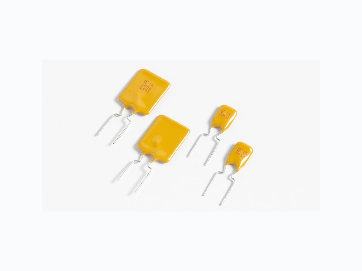
- General Electronics I hold = Hold current: maximum current device will pass without tripping in 20°C still air. I trip = Trip current: minimum current at which the device will trip in 20°C still air. V max = Maximum voltage device can withstand without damage at rated current (Imax) I max = Maximum fault current device can withstand without damage at rated voltage (Vmax) Pd = Power dissipated from device when in the tripped state at 20°C still air. R min = Minimum resistance of device in initial (un-soldered) state. R 1max = Maximum resistance of device at 20°C measured one hour after tripping. Caution: Operation beyond the specified rating may result in damage and possible arcing and flame. Agency Approvals * Effective January 1, 2010, all 16R PTC products will be manufactured Halogen Free (HF). Existing Non-Halogen Free 16R PTC products may continue to be sold, until supplies are depleted. 16R Series RoHS AGENCY AGENCY FILE NUMBER E183209 R501 19318 Additional Information Datasheet SamplesResources Samples
© 2017 Littelfuse, Inc. Specifications are subject to change without notice. Revised: 03/22/17 Radial Leaded > 16R Series T emperature Rerating CurveAverage Time Current Curves Ambient Operation Temperature -40°C -20°C 0°C 20°C 40°C 50°C 60°C 70°C 85°C Part Number Hold Current (A) T emperature Rerating The average time current curves and Temperature Rerating curve performance is affected by a number or variables, and these curves provided as guidance only. Customer must verify the performance in their application. Note: Typical Temperature rerating curve, refer to table for derating data -40 -30 -20 -10 01 02 03 04 05 06 07 08 0 10% 30% 50% 70% 90% 110% 130% 150% 170% Temperature (°C) Percentage of Rated Current T emperature Rerating Curve 2.5 A 3.0 A 4.0 A 5.0 A 6.0 A 7.0 A 8.0 A 9.0 A 10.0 A 11.0 A 12.0 A 14.0 A 0.0001 0.001 0.01 0.1 11 0 100 1000 Current in Amperes Time in Hectoseconds (100 Seconds)
© 2017 Littelfuse, Inc. Specifications are subject to change without notice. Revised: 03/22/17 Radial Leaded > 16R Series Environmental Specifications Operating/Storage T emperature -40°C to +85°C Maximum Device Surface T emperature in T ripped State 125°C Passive Aging +85°C, 1000 hours -/+ 5% typical resistance change Humidity Aging +85°C, 85% R.H., 1000 hours -/+ 5% typical resistance change Thermal Shock +85°C to -40°C 10 times -/+ 5% typical resistance change Solvent Resistance MIL–STD–202, Method 215 No change Moisture Resistance Level Level 1, J–STD–020 Physical Specifications Lead Material 2.5A: Tin-plated Copper clad Steel 3.0 - 14.0A: Tin-plated Copper Soldering Characteristics Solderability per MIL–STD–202, Method 208 Insulating Material Cured, flame retardant epoxy polymer meets UL 94V-0 requirements. Device Labeling Marked with ‘LF’, voltage, current rating, and date code. Soldering Parameters - Wave Soldering Pre-Heating Zone Refer to the condition recommended by the flux manufacturer. Max. ramping rate should not exceed 4°C/ Sec. Soldering Zone Max. solder temperature should not exceed 260°C Time within 5°C of actual Max. solder temperature within 3 – 5 seconds Total time from 25°C room to Max. solder temperature within 5 minutes including Pre-Heating time Cooling Zone Cooling by natural convection in air. Max. ramping down rate should not exceed 6°C/Sec. Preheating 100 125 255 260 5 max. Temperature(°C) SolderingC ooling 60 - 180 Time(s)
© 2017 Littelfuse, Inc. Specifications are subject to change without notice. Revised: 03/22/17 Radial Leaded > 16R Series Dimensions Part Number Figu re A B C D E F Physical Characteristics Inches mm Inches mm Inches mm Inches mm Inches mm Inches mm Lead (dia) Material CuFe 16R700G Part Marking System Figure 2Figure 1 WARNING
- Users shall independently assess the suitability of these devices for each of their applications
- Operation of these devices beyond the stated maximum ratings could result in damage to the devices and lead to electrical arcing and/or fire
- These devices are intended to protect against the effects of temporary over-current or over-temperature conditions and are not intended to perform as protective devices where such conditions are expected to be repetitive or prolonged in duration
- Exposure to silicon-based oils, solvents, electrolytes, acids, and similar materials can adversely affect the performance of these PPTC devices
- These devices undergo thermal expansion under fault conditions, and thus shall be provided with adequate space and be protected against mechanical stresses
- Circuits with inductance may generate a voltage (L di/dt) above the rated voltage of the PPTC device. A E B C F E F D A B C D Single Sided Marking 250G XXXX Voltage Rating Current Rating Date Code (Contact Littelfuse for additional information) Littelfuse Trademark
© 2017 Littelfuse, Inc. Specifications are subject to change without notice. Revised: 03/22/17 Radial Leaded > 16R Series Packaging Options Part Number Ordering Number I hold (A) I hold Code Packaging Option Quantity Quantity & Packaging Codes 16R250G 16R250GU 2.50 250 Bulk 500 U 16R250GPR Tape and Ammo 2000 PR 16R300G 16R300GU 3.00 300 Bulk 500 U 16R300GPR Tape and Ammo 2000 PR 16R400G 16R400GU 4.00 400 Bulk 500 U 16R400GPR Tape and Ammo 2000 PR 16R500G 16R500GU 5.00 500 Bulk 500 U 16R500GPR Tape and Ammo 2000 PR 16R600G 16R600GU 6.00 600 Bulk 500 U 16R600GDR Tape and Ammo 1500 DR 16R700G 16R700GF 7. 0 0 700 Bulk 200 F 16R700GKLF 16R700GMR Tape and Ammo 1000 MR 16R700GKLMR 16R800G 16R800GF 8.00 800 Bulk 200 F 16R800GMR Tape and Ammo 1000 MR 16R900G 16R900GF 9.00 900 Bulk 200 F 16R900GMR Tape and Ammo 1000 MR 16R1000G 16R1000GF 10.00 1000 Bulk 200 F 16R1000GMR Tape and Ammo 1000 MR 16R1100G 16R1100GF 11. 0 0 110 0 Bulk 200 F 16R1100GMR Tape and Ammo 1000 MR 16R1200G 16R1200GH 12.00 1200 Bulk 100 H 16R1200GMR Tape and Ammo 1000 MR 16R1400G 16R1400GH 14.00 1400 Bulk 100 H Part Ordering Number System PACKAGING STYLE I HOLD CURRENT CODE (SEE TABLE BELOW) QUANTITY CODE: F=200 H=100 M=1000 D=1500 P=2000 U=500 BLANK: Bulk R: Tape & Ammo
16 R 700 G KL M R
TYPE: G (16VDC) Kinked Lead Device Option Identifier (16R700GKL product only) R: RADIAL SERIES VOLTAGE RATING (VDC) Disclaimer Notice - Information furnished is believed to be accurate and reliable. However, users should independently evaluate the suitability of and test each product selected for their own applications. Littelfuse products are not designed for, and may not be used in, all applications. Read complete Disclaimer Notice at www.littelfuse.com/disclaimer-electronics.
© 2017 Littelfuse, Inc. Specifications are subject to change without notice. Revised: 03/22/17 Radial Leaded > 16R Series T ape and Ammo Specifications Devices taped using EIA468-B/IE286-2 standards. See table below and Figure 1 for details. Dimension EIA Mark IEC Mark Dimensions Dim. (mm) T ol. (mm) Carrier tape width W W 18 -0.5 /+1 .0 Hold down tape width: W4 W0 11 min. Top distance between tape edges W6 W2 3 max. Sprocket hole position W5 W1 9 -0.5 /+0.75 Sprocket hole diameter* D0 D0 4 -0.32 /+0.2 Abscissa to plane(straight lead) H H 18.5 -/+ 3.0 Abscissa to plane(kinked lead) H0 H0 16 -/+ 0.5 Abscissa to top 45.0 max. Overall width w/o lead protrusion 56 max. Overall width w/ lead protrusion 57 max. Lead protrusion L1 l1 1. 0 max. Protrusion of cut out L L 11 max. Protrusion beyond hold-down tape l2 l2 Not specified Sprocket hole pitch P0 P0 25.4 -/+ 0.5 Device pitch: 25.4 Pitch tolerance 20 consecutive. -/+ 1 Tape thickness t t 0.9 max. Tape thickness with splice t1 2.0 max. Splice sprocket hole alignment 0 -/+ 0.3 Body lateral deviation Δh Δh 0 -/+ 1 .0 Body tape plane deviation Δp Δp 0 -/+ 1 .3 Ordinate to adjacent component lead* P1 P1 3.81 -/+ 0.7 Ordinate to adjacent component lead* 7 .62 -/+ 0.7 Lead spacing:16R250G-16R1100G F F 5.08 -/+ 0.8 Lead spacing:16R1200G-16R1400G F F 10.18 -/+ 0.8 *Differs from EIA specification A B L1 P0 D0 F L W Reference plane ∆h ∆h H ∆h ∆p Direction of unreeling Cross section A - B t Cross section Optional shape: Circular or polygonal Direction of unreeling Reel Tape Upper side Lower side T ape and Ammo Diagram Figure 1