
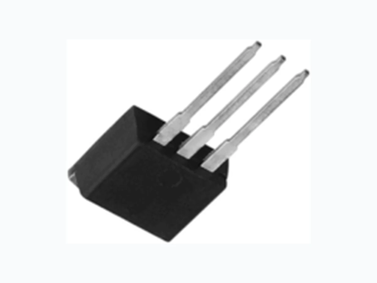
16CTU04SPBF_10 VISHAY
Document overview
- Manufacturer or author: Provided By digicamel.com
- PDF pages: 9
Technical content
Document Number: 94009 For tec hnical questions, contact: diodestech@vishay.com www.vishay.com Revision: 11-Mar-10 1 Ultrafast Rectifier, 2 x 8 A FRED Pt® VS-16CTU04SPbF, VS-16CTU04-1PbF Vishay High Power Products
FEATURES
- Ultrafast recovery time
- Low forward voltage drop
- Low leakage current
- 175 °C operating junction temperature
- Meets MSL level 1, per J-STD-020, LF maximum peak of 260 °C
- Halogen-free according to IEC 61249-2-21 definition
- Compliant to RoHS directive 2002/95/EC
- AEC-Q101 qualified DESCRIPTION/APPLICATIONS Vishay HPP’s FRED Pt ® series are the state of the art ultrafast recovery rectifiers specifically designed with optimized performance of forward voltage drop and ultrafast recovery time. The planar structure and th e platinum doped life time control, guarantee the best overall performance, ruggedness and reliability characteristics. These devices are intended for use in the output rectification stage of SMPS, UPS, dc-to- dc converters as well as freewheeling diode in low voltage inverters and chopper motor drives. Their extremely optimized stored charge and low recovery current minimize the switch ing losses and reduce over dissipation in the switching element and snubbers. PRODUCT SUMMARY trr 60 ns IF(AV) 2 x 8 A VR 400 V V S-16CTU04SPbF D2PAK VS-16CTU04-1PbF TO-262 Anode 1 3 Base Common Cathode Common Cathode Anode Anode 1 3 Base Common Cathode Common Cathode Anode ABSOLUTE MAXIMUM RATINGS PARAMETER SYMBOL TEST CONDITIONS VALUES UNITS Peak repetitive reverse voltage V RRM 400 V Average rectified forward current per leg IF(AV) A total device Rated V R, TC = 155 °C 16 Non-repetitive peak surge current I FSM TC = 25 °C 100 Peak repetitive forward current I FRM Rated VR, square wave, 20 kHz, TC = 155 °C 16 Operating junction and storage temperatures T J, TStg - 65 to 175 °C ELECTRICAL SPECIFICATIONS PER LEG (TJ = 25 °C unless otherwise specified) PARAMETER SYMBOL TEST CONDITI ONS MIN. TYP. MAX. UNITS Breakdown voltage, blocking voltage VBR, VR IR = 100 μA 400 - - V Forward voltage V F IF = 8 A - 1.19 1.3 IF = 8 A, TJ = 150 °C - 0.94 1.0 Reverse leakage current I R VR = VR rated - 0.2 10 μA TJ = 150 °C, VR = VR rated - 20 500 Junction capacitance C T VR = 400 V - 14 - pF Series inductance L S Measured lead to lead 5 mm from package body - 8.0 - nH
www.vishay.com For technical questions, contact: diodestech@vishay.com Document Number: 94009
2 Revision: 11-Mar-10
VS-16CTU04SPbF, VS-16CTU04-1PbF Vishay High Power Products Ultrafast Rectifier, 2 x 8 A FRED Pt® DYNAMIC RECOVERY CHARACTERISTICS PER LEG (TJ = 25 °C unless otherwise specified) PARAMETER SYMBOL TEST CONDITIO NS MIN. TYP. MAX. UNITS Reverse recovery time t rr IF = 1.0 A, dIF/dt = 50 A/μA, VR = 30 V - 35 60 nsTJ = 25 °C IF = 8 A dIF/dt = 200 A/μs VR = 200 V -4 3- TJ = 125 °C - 67 - Peak recovery current I RRM TJ = 25 °C - 2.8 - A Reverse recovery charge Q rr TJ = 25 °C - 60 - nC TJ = 125 °C - 210 - THERMAL - MECHANICAL SPECIFICATIONS PARAMETER SYMBOL TEST CONDITIONS MIN. TYP. MAX. UNITS Maximum junction and storage temperature range TJ, TStg - 65 - 175 °C Thermal resistance, junction to case per leg RthJC -1 . 8 2 . 0 °C/WThermal resistance, junction to ambient per leg RthJA Typical socket mount - - 50 Thermal resistance, case to heatsink RthCS Mounting surface, flat, smooth and greased -0 . 5- Weight -2 . 0- g -0 . 0 7- o z . Mounting torque 6.0 (5.0) - 12 (10) kgf · cm (lbf · in) Marking device Case style D2PAK 16CTU04S Case style TO-262 16CTU04-1
Document Number: 94009 For tec hnical questions, contact: diodestech@vishay.com www.vishay.com Revision: 11-Mar-10 3 VS-16CTU04SPbF, VS-16CTU04-1PbF Ultrafast Rectifier, 2 x 8 A FRED Pt® Vishay High Power Products Fig. 1 - Typical Forward Voltage Drop Characteristics Fig. 2 - Typical Values of Reverse Current vs. Reverse Voltage Fig. 3 - Typical Junction Capacitance vs. Reverse Voltage Fig. 4 - Maximum Thermal Impedance ZthJC Characteristics 100 VF - Forward Voltage Drop (V) IF - Instantaneous Forward Current (A) 0.1 TJ = 175 °C TJ = 150 °C TJ = 25 °C 0.001 0.01 0.1 100 1000 0 100 200 300 400 0.0001 VR - Reverse Voltage (V) IR - Reverse Current (µA) TJ = 175 °C TJ = 150 °C TJ = 125 °C TJ = 100 °C TJ = 25 °C TJ = 25 °C 0 100 200 300 400 1000 100 VR - Reverse Voltage (V) CT - Junction Capacitance (pF) 0.01 0.1 t1 - Rectangular Pulse Duration (s) ZthJC - Thermal Impedance (°C/W) Single pulse (thermal resistance) PDM Notes: 1. Duty factor D = t1/t2 2. Peak TJ = PDM x ZthJC + TC D = 0.50 D = 0.20 D = 0.10 D = 0.05 D = 0.02 D = 0.01
www.vishay.com For technical questions, contact: diodestech@vishay.com Document Number: 94009
4 Revision: 11-Mar-10
VS-16CTU04SPbF, VS-16CTU04-1PbF Vishay High Power Products Ultrafast Rectifier, 2 x 8 A FRED Pt® Fig. 5 - Maximum Allowable Case Temperature vs. Average Forward Current Fig. 6 - Forward Power Loss Characteristics Fig. 7 - Typical Reverse Recovery Time vs. dIF/dt Fig. 8 - Typical Stored Charge vs. dIF/dt Note (1) Formula used: TC = TJ - (Pd + PdREV) x RthJC; Pd = Forward power loss = IF(AV) x VFM at (IF(AV)/D) (see fig. 6); PdREV = Inverse power loss = VR1 x IR (1 - D); IR at VR1 = Rated VR See note (1) Square wave (D = 0.50) Rated VR applied DC 02468 1 2 10 180 170 160 150 140 130 IF(AV) Average Forward Current (A) Allowable Case Temperature (°C) 02468 1 2 10 IF(AV) - Average Forward Current (A) Average Power Loss (W) RMS limit D = 0.01 D = 0.02 D = 0.05 D = 0.1 D = 0.2 D = 0.5 DC 100 1000 trr (ns) dIF/dt (A/µs) IF = 16 A IF = 8 A VR = 200 V TJ = 125 °C TJ = 25 °C 500 100 1000 Qrr (nC) dIF/dt (A/µs) 100 200 300 400 450 IF = 16 A IF = 8 A 150 250 350 VR = 200 V TJ = 125 °C TJ = 25 °C
Document Number: 94009 For tec hnical questions, contact: diodestech@vishay.com www.vishay.com Revision: 11-Mar-10 5 VS-16CTU04SPbF, VS-16CTU04-1PbF Ultrafast Rectifier, 2 x 8 A FRED Pt® Vishay High Power Products Fig. 9 - Reverse Recovery Parameter Test Circuit Fig. 10 - Reverse Recovery Waveform and Definitions IRFP250 D.U.T. L = 70 μH VR = 200 V 0.01 Ω G D S dIF/dt adjust Qrr
0.5 IRRM
dI(rec)M/dt
0.75 IRRM
(1) (2) (3) (4) (5) (1) dIF/dt - rate of change of current through zero crossing (2) IRRM - peak reverse recovery current (3) trr - reverse recovery time measured from zero crossing point of negative going IF to point where a line passing through 0.75 IRRM and 0.50 IRRM extrapolated to zero current. (4) Qrr - area under curve defined by trr and IRRM trr x IRRM 2Qrr = (5) dI(rec)M/dt - peak rate of change of current during tb portion of trr
www.vishay.com For technical questions, contact: diodestech@vishay.com Document Number: 94009
6 Revision: 11-Mar-10
VS-16CTU04SPbF, VS-16CTU04-1PbF Vishay High Power Products Ultrafast Rectifier, 2 x 8 A FRED Pt® ORDERING INFORMATION TABLE 2 - Current rating (16 A) 3 - C = Common cathode 4 - T = TO-220, D 2PAK 5 - U = Ultrafast recovery 6 - Voltage rating (04 = 400 V) - PbF = Lead (Pb)-free 7 - S = D2PAK -1 = TO-262 8 - None = Tube (50 pieces) TRL = Tape and reel (left oriented, for D2PAK package) TRR = Tape and reel (right oriented, for D2PAK package) Device code 51 324 6789 VS- 16 C T U 04 S TRL PbF - HPP product suffix LINKS TO RELATED DOCUMENTS Dimensions www.vishay.com/doc?95014 Part marking information www.vishay.com/doc?95008 Packaging information www.vishay.com/doc?95032
Document Number: 95014 For technical questi ons concerning discrete products, contact: diodes-tech@vishay.com www.vishay.com Revision: 31-Mar-09 For technical questi ons concerning module products, contact: ind-modules@vishay.com D2PAK, TO-262 Outline Dimensions Vishay High Power Products DIMENSIONS FOR D2PAK in millimeters and inches Notes (1) Dimensioning and tolerancing per ASME Y14.5 M-1994 (2) Dimension D and E do not include mold flash. Mold flash shall not exceed 0.127 mm (0.005") per side. These dimensions are measured at the outmost extremes of the plastic body (3) Thermal pad contour optional within dimension E, L1, D1 and E1 (4) Dimension b1 and c1 apply to base metal only (5) Datum A and B to be determined at datum plane H (6) Controlling dimension: inch (7) Outline conforms to JEDEC outline TO-263AB c B Detail A AA A ± 0.004 BM A Lead tip (3) (3) View A - A (E) (D1) B H Detail “A” Rotated 90 °CW Scale: 8:1 L Gauge plane 0° to 8° Seating plane Section B - B and C - C Scale: None (4) (4) (b, b2) b1, b3 (c) Base MetalPlating Conforms to JEDEC outline D2PAK (SMD-220) 13 2 D C A E (2)(3) (2) H BB 2 x b 2 x b2
0.010 A BMM
(3) e2 x Pad layout MIN.11.00 (0.43) MIN.9.65 (0.38) MIN.3.81 (0.15) MIN.2.32 (0.08) 17.90 (0.70) 15.00 (0.625) 2.64 (0.103) 2.41 (0.096) Lead assignments Diodes 1. - Anode (two die)/open (one die) 2., 4. - Cathode 3. - Anode
www.vishay.com For technical questions c oncerning discrete products, contact: diodes-tech@vishay.com Document Number: 95014 2 For technical questions concer ning module products, contact: ind-modules@vishay.com Revision: 31-Mar-09 Outline Dimensions Vishay High Power Products D2PAK, TO-262 DIMENSIONS FOR TO-262 in millimeters and inches Notes (1) Dimensioning and tolerancing as per ASME Y14.5M-1994 (2) Dimension D and E do not include mold flash. Mold flash shall not exceed 0.127 mm (0.005") per side. These dimensions are measured at the outmost extremes of the plastic body (3) Thermal pad contour optional within dimension E, L1, D1 and E1 (4) Dimension b1 and c1 apply to base metal only (5) Controlling dimension: inches (6) Outline conform to JEDEC TO-262 except A1 (maximum), b (minimum) and D1 (minimum) where dimensions derived the actual package outline SYMBOL MILLIMETERS INCHES NOTESMIN. MAX. MIN. MAX. A 4.06 4.83 0.160 0.190 A1 2.03 3.02 0.080 0.119 b 0.51 0.99 0.020 0.039 b1 0.51 0.89 0.020 0.035 4 b2 1.14 1.78 0.045 0.070 b3 1.14 1.73 0.045 0.068 4 c 0.38 0.74 0.015 0.029 c1 0.38 0.58 0.015 0.023 4 c2 1.14 1.65 0.045 0.065 D 8.51 9.65 0.335 0.380 2 D1 6.86 8.00 0.270 0.315 3 E 9.65 10.67 0.380 0.420 2, 3 E1 7.90 8.80 0.311 0.346 3 e 2.54 BSC 0.100 BSC L 13.46 14.10 0.530 0.555 L1 - 1.65 - 0.065 3 L2 3.56 3.71 0.140 0.146 (4) (4) Base metalPlating b1, b3 (b, b2) c1c Section B - B and C - C Scale: None Section A - A (3)E1 (3)D1 E BA A A c Seating plane Lead tip (3) (2) (3) (2) AE (Datum A) B B C C 321 L D 2 x e 3 x b2 3 x b Modified JEDEC outline TO-262 Lead assignments Diodes 1. - Anode (two die)/open (one die) 2., 4. - Cathode 3. - Anode
Document Number: 91000 www.vishay.com Revision: 11-Mar-11 1 Disclaimer Legal Disclaimer Notice Vishay ALL PRODUCT, PRODUCT SPECIFICATIONS AND DATA AR E SUBJECT TO CHANGE WITHOUT NOTICE TO IMPROVE RELIABILITY, FUNCTION OR DESIGN OR OTHERWISE. Vishay Intertechnology, Inc., its affiliates, agents, and employees, and all persons acting on its or their behalf (collectivel y, “Vishay”), disclaim any and all liability for any errors, inaccuracies or incompleteness contained in any datasheet or in any other disclosure relating to any product. Vishay makes no warranty, representation or guarantee regarding the suitability of the products for any particular purpose or the continuing production of any product. To the maximum extent permitted by applicable law, Vishay disclaims (i) any and all liability arising out of the application or use of any product, (ii) any and all liability, incl uding without limitation specia l, consequential or incidental dama ges, and (iii) any and all impl ied warranties, including warran ties of fitness for particular purpose, non-infringement and merchantability. Statements regarding the suitability of pro ducts for certain types of applications are based on Vishay’s knowledge of typical requirements that are often placed on Vishay products in gene ric applications. Such statements are not binding statements about the suitability of products for a partic ular application. It is the customer’s responsibility to validate that a particu lar product with the properties described in th e product specification is su itable for use in a particul ar application. Parameters provided in datasheets an d/or specifications may vary in different applications and perfo rmance may vary over time. All operating parameters, including typical pa rameters, must be validated for each customer application by the customer’s technical experts. Product specifications do not expand or otherwise modify Vishay’s term s and conditions of purchase, including but not limited to the warranty expressed therein. Except as expressly indicated in writing, Vishay products are not designed for use in medical, life-saving, or life-sustaining applications or for any other application in which the failure of the Vishay product co uld result in person al injury or death. Customers using or selling Vishay products not expressly indicated for use in such applications do so at their own risk and agree to fully indemnify and hold Vishay and it s distributors harmless from and against an y and all claims, liabilities, expenses and damages arising or resulting in connection with such use or sale, including attorneys fees, even if such claim alleges that Vishay or its distributor was negligent regarding the design or manufacture of the part. Please contact authorized Vishay personnel to obtain written terms and conditions regarding products designed for such applications. No license, express or implied, by estoppel or otherwise, to any intellectual property rights is granted by this document or by any conduct of Vishay. Product names and markings noted herein may be trademarks of their respective owners.