

 Download PDF
165-62 AMPHENOL
Document overview
- PDF pages: 10
Technical content
Page 1
Amphenol 67 and 165 Series
®
Miniaturized Standard Connectors
Amphenol
Page 2
Table of Contents
Page No.
Amphenol® 67 Series “Minni E”
General Information, Design Characteristics, Customer Options. . . . . . . . . . . . . . . . . . . . . . . . . 1
Connector Applications, Mounting Dimensions . . . . . . . . . . . . . . . . . . . . . . . . . . . . . . . . . . . . . 2, 3
Insert Arrangements. . . . . . . . . . . . . . . . . . . . . . . . . . . . . . . . . . . . . . . . . . . . . . . . . . . . . . . . . . . . 4
How to Order . . . . . . . . . . . . . . . . . . . . . . . . . . . . . . . . . . . . . . . . . . . . . . . . . . . . . . . . . . . . . . . . . 5
Amphenol® 165 Series - Miniaturized MIL-C-5015
General Information, Design Characteristics, Customer Options. . . . . . . . . . . . . . . . . . . . . . . . . 6
Connector Applications. . . . . . . . . . . . . . . . . . . . . . . . . . . . . . . . . . . . . . . . . . . . . . . . . . . . . . . . . . 7
Insert Arrangements, Ordering Information . . . . . . . . . . . . . . . . . . . . . . . . . . . . . . . . . . . . . . . . . . 8
Sales Office Listing
Page 3
Amphenol 67 Series “Minni E”
®
environmental resistant cylindrical connectors
Voltage Rating
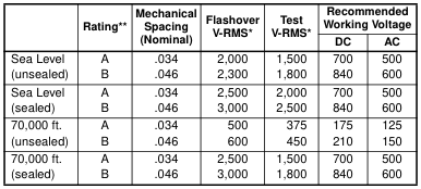
\* RATING - “B” rating is for insert 14-5 which takes a higher voltage; “A” rating is for other inserts. \*\* TYPICAL FLASHOVER VOLTAGES AT STANDARD CONDITIONS (unsealed) Refers to connectors with no provisions for sealing front or rear areas. (sealed) Refers to connectors that are potted or pressurized in mounting, with front and rear areas sealed.
DESIGN CHARACTERISTICS
- Approximately half the weight of standard cylindricals
- Quick, positive, stainless steel bayonet coupling
- Operating temperatures from -67°F to +257°F per
MIL-C-5015
- Sealed connectors capable of 1500 VRMS at 70,000 ft. altitude
- Vibration resistance of 10 to 2,000 cps at 20Gs
- Interfacial seal of neoprene rubber with individual contact barriers
- Moisture resistance exceeds MIL-C-5015 require- ments with potting
- UL approved recognition file E115497
CUSTOMER OPTIONS
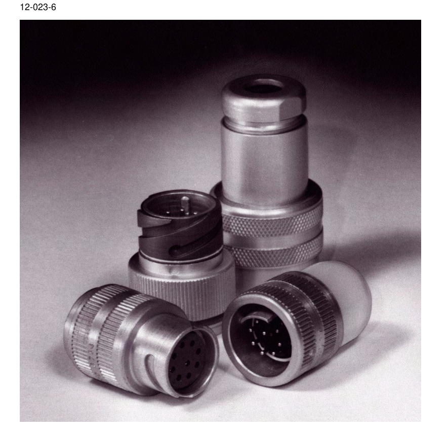
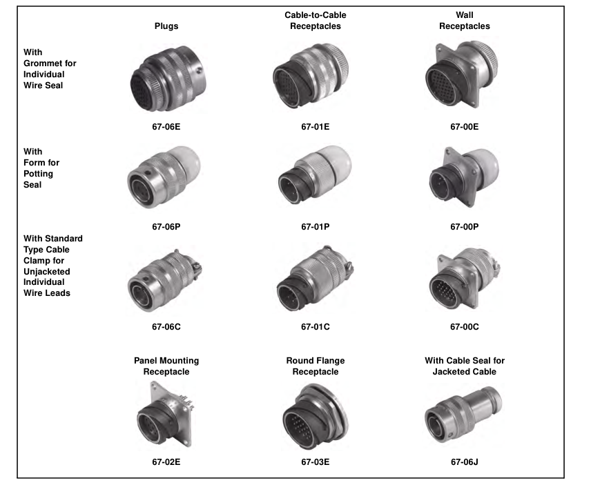
- Five shell styles
- Choice of unitized back end grommet or provision for potting
- Seventeen insert configurations
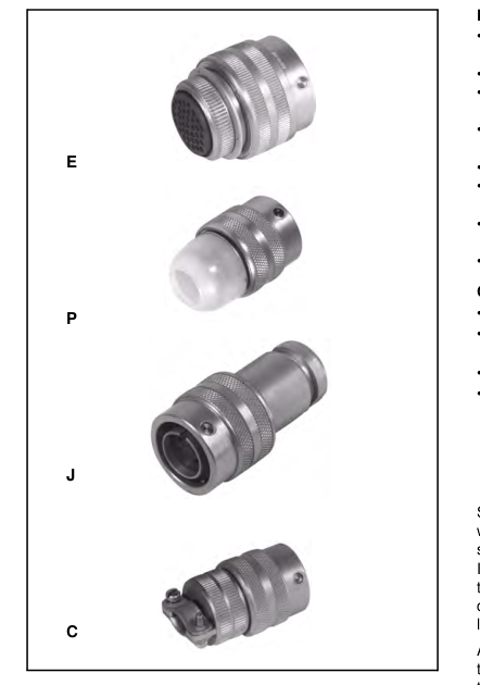
- Four construction classes available:
- E - with unitized grommet for individual wire seal
- P - includes potting mold
- J - sealing clamp for jacketed cable
- C - vise action with two-screw strain relief
Shell components are fabricated from high grade aluminum with gray anodize finish and stainless steel bayonet pins and slots. Contacts are copper alloy gold over nickel plate. Inserts are diallyl phthalate, providing high arc and insulation resistance under both humidity and thermal stress conditions. Positive locking action is provided by the springloaded coupling ring. Amphenol® 67 Series connectors are ideal for applications that require a light to medium weight, durable, environmentally sealed connector. For additional information on Amphenol® 67 Series connectors, or for special application requirements, contact your local sales office, authorized distributor, or
Amphenol Corporation Amphenol Aerospace 40-60 Delaware Avenue Sidney, New York 13838-1395 Phone: 607-563-5011 Fax: 607-563-5157 www.amphenol-aerospace.com
Amphenol Aerospace is a certified ISO 9001 manufacturer.
Page 4
67 Series
connector applications
Mounting Dimensions (For all 67 Series square flange connectors)
| Connector Size | A | B | Suggested Mounting Hole |
| 12 | .812 | 1.031 | .700 |
| 14 | .906 | 1.125 | .822 |
| 18 | 1.062 | 1.312 | 1.072 |
| 20 | 1.156 | 1.437 | 1.197 |
| 22 | 1.250 | 1.562 | 1.291 |
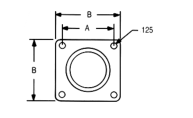
NOTE: All dimensions for reference only.
Page 5
67 Series
connector applications
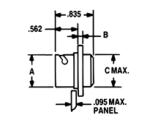
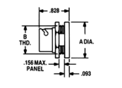
Suggested
67-02E
67-03E
Mounting Hole
| Connector Size | A | B | C |
| 12 | .662 | .062 | .690 |
| 14 | .781 | .062 | .812 |
| 18 | 1.032 | .093 | 1.062 |
| 20 | 1.156 | .093 | 1.187 |
| 22 | 1.281 | .093 | 1.281 |
| Connector Size | A | B | E | F |
| 12 | 1.031 | .750 | .695 | .755 |
| 14 | 1.156 | .875 | .820 | .880 |
| 18 | 1.406 | 1.125 | 1.079 | 1.130 |
| 20 | 1.531 | 1.250 | 1.195 | 1.255 |
| 22 | 1.656 | 1.375 | 1.320 | 1.380 |
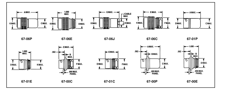
| Connector Size | A | B | C | D | E | F | G | H | J | K |
| 12 | 1.687 | .093 | .795 | .895 | 1.870 | .817 | 1.937 | .706 | .250 | .957 |
| 14 | 1.687 | .093 | .920 | 1.000 | 1.870 | .967 | 1.937 | .812 | .375 | 1.082 |
| 18 | 1.687 | .093 | 1.170 | 1.250 | 1.870 | 1.185 | 1.937 | 1.062 | .656 | 1.375 |
| 20 | 1.734 | .093 | 1.223 | 1.375 | 1.970 | 1.312 | 2.312 | 1.187 | .750 | 1.500 |
| 22 | 1.734 | .093 | 1.352 | 1.468 | 1.970 | 1.440 | 2.312 | 1.317 | .875 | 1.625 |
NOTE: All dimensions for reference only.
Page 6
67 Series
insert arrangements
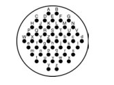
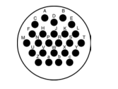
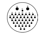
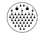
front face of insert illustrated
Insert Arrangement
12-7
12-60
14-5
14-9
14-12
Number of Contacts
7
3
5
9
12
Contact Size
20
16
20
20
20
Insert Arrangement
14-61
14-63
18-24
18-62
Number of Contacts
8
5
24
19
Contact Size
20
16
20
20
plus 1 shielded contact
plus 1 shielded contact
Insert Arrangement
18-64
18-65
20-37
20-66
Number of Contacts
14
7 4
37
19
Contact Size
16
20 16
20
16
Insert Arrangement
22-67
22-48
22-68
22-69
Number of Contacts
25
48
36 2
40 2
Contact Size
16
20
20 16
20 16
Current rating - #20 contact: 7.5 amps, #16 contact: 12 amps
Contact Legend
Shielded contact: 7.5 amps
shielded
Page 7
67 Series
how to order
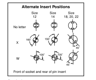
Amphenol® 67 Series “Minni E” Connectors can be ordered by coded part number. Ordering procedure is illustrated by part number 67-06E12-7PW-100 as shown below:
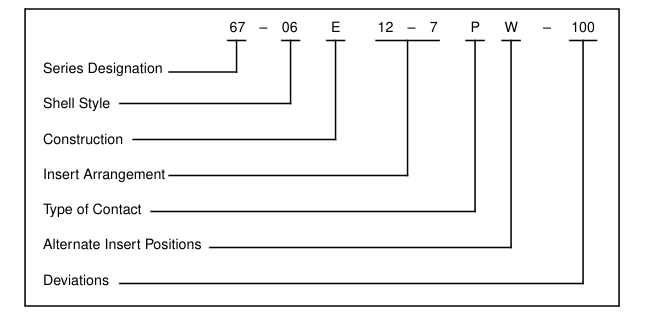
Series Designation 67 –
Shell Style 00 - Wall mounting receptacle 01 - Cable mounting receptacle 02 - Panel mount receptacle 03 - Rear panel mount, round flange receptacle 06 - Cable plug - straight
Construction E Environmentally sealed (Unitized grommet) P Environmentally sealed (Disposable polyethylene potting form furnished) J Sealing clamp for jacketed cable (Waterproof) C Mechanical Clamp (Sealed only when potted)
Insert Arrangement See available insert arrangements, page 4
Type of Contact P - Pin S - Socket
Deviations 100 - 100 µin. gold over silver contacts 106 - Pretinned solder wells 113 - Aluminum parts iridite finish
Page 8
®
Amphenol 165 Series
miniaturized standard connectors
DESIGN CHARACTERISTICS
- Approximately one-third the size and weight of standard MIL-C-5015 connectors
- Quick, positive, bayonet coupling
- O-ring seals in both plugs and receptacles make connectors pressure proof and water protected when mated
- Meets pressure seal requirements of MIL-C-5015, Class C construction
- UL approved recognition file E115497
CUSTOMER OPTIONS
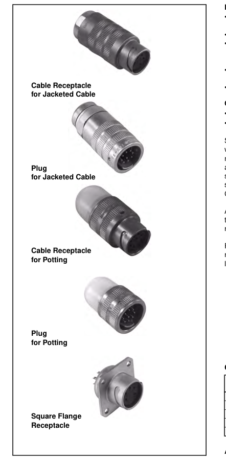
- Five shell styles in two sizes - large and small
- Seven insert configurations
Shell components are fabricated from high grade aluminum with gray anodize finish. Contacts are copper alloy gold over nickel plate. Inserts are diallyl phthalate, providing high arc and insulation resistance under both humidity and thermal stress conditions. Connectors using female inserts feature a sandwich construction with the insert spun into a cartridge. Connectors are factory sealed to prevent leakage.
Amphenol® 165 Series connectors are ideal for applications that demand a lightweight connector that meets MIL-C-5015 requirements.
For additional information on Amphenol® 165 Series connectors, or for special application requirements, contact your local sales office, authorized distributor, or Amphenol Corporation Amphenol Aerospace 40-60 Delaware Avenue Sidney, New York 13838-1395 Phone: 607-563-5011 Fax: 607-563-5157
Connector Weights
| Style | Weight (pounds) | |
| Small | Large | |
| Cable receptacle for potting | 0.0415 | 0.0599 |
| Cable receptacle | 0.0600 | 0.0945 |
| Panel receptacle | 0.0264 | 0.0439 |
| Plug | 0.0659 | 0.0975 |
| Plug for potting | 0.0302 | 0.0490 |
Amphenol Aerospace is a certified ISO 9001 manufacturer.
Page 9
165 Series
connector applications
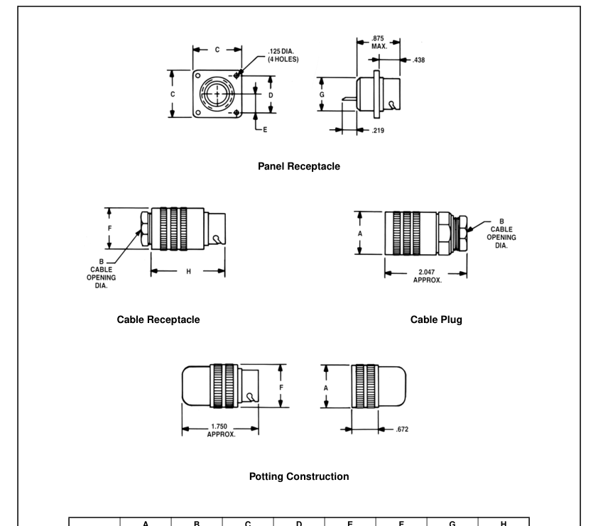
| A | B | C | D | E | F | G | H | |
| Small | .891 | .375* | 1.063 | .781 | .391 | .875 | .813 | 1.922 |
| Large | 1.141 | .656 | 1.313 | .969 | .484 | 1.125 | 1.063 | 1.938 |

Page 10
165 Series
insert arrangements, order information
front face of insert illustrated
The following chart provides ordering information. For example, to
order a 165 Series plug with pin contacts use part number 165-33.
| Insert Arrangements | Insert Style | Plug | Receptacle Sq. Flange | Cable Receptacle | Potting Constructions | |
| Plug | Receptacle | |||||
| 5 #20 contacts Current Rating (Amperes) 7.5 Voltage rating (Volts RMS at sea level) 600 | Pin Socket | 165-33 165-34 | 165-35 165-36 | 165-35-1002 165-36-1003 | 165-33-1000 165-34-1000 | 165-35-1000 165-36-1000 |
| 9 #20 contacts Current Rating (Amperes) 7.5 Voltage rating (Volts RMS at sea level) 500 | Pin Socket | 165-13 165-14 | 165-15 165-16 | 165-15-1002 165-16-1003 | 165-13-1000 165-14-1000 | 165-15-1000 165-16-1000 |
| 8 #20 contacts, 1 Shielded contact Current Rating (Amperes) 10.0 Voltage rating (Volts RMS at sea level) 500 | Pin Socket | 165-82 165-61-1008 | 165-73 165-83 | 165-73-1001 165-83-1001 | 165-82-1000 165-61 | 165-73-1000 165-83-1000 |
| 12 #20 contacts Current Rating (Amperes) 7.5 Voltage rating (Volts RMS at sea level) 500 | Pin Socket | 165-9 165-10 | 165-11 165-12 | 165-11-1002 165-12-1002 | 165-9-1000 165-10-1000 | 165-11-1000 165-12-1000 |
| 14 #16 contacts Current Rating (Amperes) 17.0 Voltage rating (Volts RMS at sea level) 500 | Pin Socket | 165-29 165-30 | 165-31 165-32 | 165-31-1003 165-32-1006 | 165-29-1000 165-30-1000 | 165-31-1000 165-32-1000 |
| 19 #20 contacts, 1 Shielded contact Current Rating (Amperes) 10.0 Voltage rating (Volts RMS at sea level) 500 | Pin Socket | 165-86 165-62-1007 | 165-84 165-85 | 165-84-1001 165-85-1001 | 165-86-1000 165-62 | 165-84-1000 165-85-1000 |
| 24 #20 contacts Current Rating (Amperes) 7.5 Voltage rating (Volts RMS at sea level) 500 | Pin Socket | 165-25 165-26 | 165-27 165-28 | 165-27-1005 165-28-1003 | 165-25-1000 165-26-1000 | 165-27-1000 165-28-1000 |