
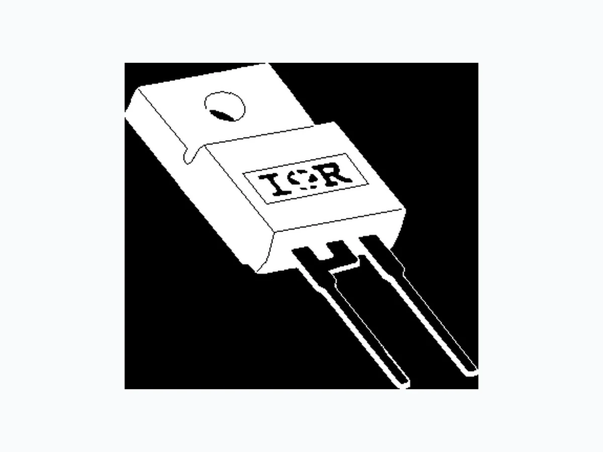
15ETH06FP IRF
Document overview
- Manufacturer or author: Provided By digicamel.com
- PDF pages: 7
Technical content
Features
Bulletin PD-20765 rev. A 02/04 2 www.irf.com VBR, Vr Breakdown Voltage, 600 - - V I R = 100µA Blocking Voltage VF Forward Voltage - 1.8 2.2 V I F = 15A, TJ = 25°C - 1.3 1.6 V I F = 15A, TJ = 150°C IR Reverse Leakage Current - 0.2 50 µA V R = VR Rated - 30 500 µA T J = 150°C, VR = VR Rated CT Junction Capacitance - 20 - pF V R = 600V LS Series Inductance - 8.0 - nH Measured lead to lead 5mm from package body Electrical Characteristics @ TJ = 25°C (unless otherwise specified) Parameters Min Typ Max Test Conditions Parameters Min Typ Max Units TJ Max. Junction Temperature Range - - 175 °C TStg Max. Storage Temperature Range - 65 - 175 RthJC Thermal Resistance, Junction to Case Per Leg - 3.0 3.5 °C/W RthJA Thermal Resistance, Junction to Ambient Per Leg - - 70 RthCS Thermal Resistance, Case to Heatsink - 0.5 - Weight - 2.0 - g - 0.07 - (oz) Mounting Torque 6.0 - 12 Kg-cm 5.0 - 10 lbf.in Thermal - Mechanical Characteristics c Typical Socket Mount d Mounting Surface, Flat, Smooth and Greased d c Units trr Reverse Recovery Time - 22 30 ns I F = 1A, diF/dt = 100A/µs, VR = 30V -2 8 3 5 I F = 15A, diF/dt = 100A/µs, VR = 30V -2 9 - T J = 25°C -7 5 - T J = 125°C IRRM Peak Recovery Current - 3.5 - A T J = 25°C -7 - T J = 125°C Qrr Reverse Recovery Charge - 57 - nC T J = 25°C - 300 - T J = 125°C trr Reverse Recovery Time - 51 - ns IRRM Peak Recovery Current - 20 - A T J = 125°C Qrr Reverse Recovery Charge - 580 - nC Dynamic Recovery Characteristics @ TC = 25°C (unless otherwise specified) IF = 15A diF /dt = 200A/µs VR = 390V Parameters Min Typ Max Test ConditionsUnits IF = 15A diF /dt = 800A/µs VR = 390V
Bulletin PD-20765 rev. A 02/04 15ETH06FP www.irf.com Fig. 1 - Typical Forward Voltage Drop Characteristics Fig. 4 - Max. Thermal Impedance Z thJC Characteristics Forward Voltage Drop - VFM (V) Instantaneous Forward Current - I F (A) Reverse Voltage - VR (V) Reverse Voltage - VR (V) Junction Capacitance - C T ( p F ) t1, Rectangular Pulse Duration (Seconds) Thermal Impedance Z thJC (°C/W) Fig. 3 - Typical Junction Capacitance Vs. Reverse Voltage Reverse Current - I R (µA) Fig. 2 - Typical Values Of Reverse Current Vs. Reverse Voltage 100 0.5 1 1.5 2 2.5 3 T = 175˚C T = 150˚C T = 25˚C J J J 0.001 0.01 0.1 100 1000 0 100 200 300 400 500 600 25˚C T = 175˚CJ 100˚C 125˚C 150˚C 100 1000 0 100 200 300 400 500 60 0 T = 25˚CJ 0.01 0.1 Single Pulse (Thermal Resistance) D = 0.50 D = 0.20 D = 0.10 D = 0.05 D = 0.02 D = 0.01 PDM Notes: 1. Duty factor D = t1/ t2 2. Peak Tj = Pdm x ZthJC + Tc
Bulletin PD-20765 rev. A 02/04 4 www.irf.com Fig. 5 - Max. Allowable Case Temperature Vs. Average Forward Current Fig. 8 - Typical Stored Charge vs. di F /dt Fig. 6 - Forward Power Loss Characteristics (3) Formula used: TC = TJ - (Pd + PdREV) x RthJC ; Pd = Forward Power Loss = IF(AV) x VFM @ (IF(AV) / D) (see Fig. 6); PdREV = Inverse Power Loss = VR1 x IR (1 - D); IR @ VR1 = rated VR Average Forward Current - IF(AV) (A) Average Forward Current - IF(AV) (A) Fig. 7 - Typical Reverse Recovery vs. di F /dt Allowable Case Temperature (°C) Average Power Loss ( Watts ) trr ( ns ) Qrr ( nC ) di F /dt (A/µs )di F /dt (A/µs ) 0 5 10 15 20 25 DC RMS Limit D = 0.01 D = 0.02 D = 0.05 D = 0.1 D = 0.2 D = 0.5 100 100 1000 IF = 30 A IF = 15 A R J J V = 390V T = 125˚C T = 25 ˚C 200 400 600 800 1000 100 1000 IF = 30 A IF = 15 A R J J V = 390V T = 125˚C T = 25 ˚C 100 120 140 160 180 0 4 8 12 16 20 24 DC Square wave (D = 0.50) 80% Rated Vr applied see note (3)
Bulletin PD-20765 rev. A 02/04 15ETH06FP www.irf.com IRFP250 D.U.T. L = 70µH V = 200VR 0.01 Ω G D S dif/dt ADJUST ta tb trr Qrr IF IRRM I RRM0.5 di(rec)M/dt
0.75 IRRM
Fig. 10 - Reverse Recovery Waveform and Definitions Fig. 9- Reverse Recovery Parameter Test Circuit Reverse Recovery Circuit diF /dt diF /dt 4. Qrr - Area under curve defined by t rr and IRRM 5. di (rec) M / dt - Peak rate of change of current during t b portion of t rr 1. diF/dt - Rate of change of current through zero crossing 2. IRRM - Peak reverse recovery current 3. trr - Reverse recovery time measured from zero crossing point of negative going IF to point where a line passing through 0.75 IRRM and 0.50 IRRM extrapolated to zero current Q rr = t rr x I RRM
Bulletin PD-20765 rev. A 02/04 6 www.irf.com Outline Table Dimensions in millimeters 5°± 0.5° 3.1 3.3 13.5 13.7 R0.5 R0.7 (2 PLACES) 3.1 HOLE ø 3.4 10.4 0.7 4.6 TYP. 5°± 0.5° 4.8 0.9 2.54 TYP. 2.54 10.6 16.4 16.0 3.7 7.1 0.48 2.85 2.8 1.4 1.15 15.4 3.2 6.7 15.8 1.05 1.3 0.44 2.65 2.6 TYP 10° Ordering Information Table Device Code 1 524 3 1 - Current Rating (15 = 15A) 2 - E = Single Diode 3 - T = TO-220 4 - H = HyperFast Recovery 5 - Voltage Rating (06 = 600V) 6 - TO-220 FULLPACK
15 E T H 06 FP
Bulletin PD-20765 rev. A 02/04 15ETH06FP www.irf.com IR WORLD HEADQUARTERS: 233 Kansas St., El Segundo, California 90245, USA Tel: (310) 252-7105 TAC Fax: (310) 252-7309 Visit us at www.irf.com for sales contact information. 02/04 Data and specifications subject to change without notice. This product has been designed and qualified for Industrial Level. Qualification Standards can be found on IR's Web site.