
159 LITTELFUSE
Document overview
- Manufacturer or author: Provided By www.digicamel.com(FREE DATASHEET DOWNLOAD SITE)
- PDF pages: 4
Technical content
Features
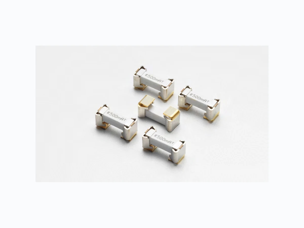
% of Ampere Rating Opening Time 100% 4 hours, Minimum 250% 1 sec., Minimum 120 secs., Maximum AGENCY AGENCY FILE NUMBER AMPERE RANGE E14721 0.5A, 1.25A, 2.0A The 159 Series product is a metal fuse clip with pre- installed Littelfuse 461 Series TeleLink® fuse. This fuse and clip combination can be automatically installed in PC Boards in one efficient manufacturing operation. It permits quick and easy fuse replacement without exposing the PC Board and other components to risks of rework solder heat as required with direct surface mount fuses. It meets UL 60950 power cross requirements and is designed to allow compliance with Telcordia GR-1089- CORE and TIA-968-A Surge Specifications. The product provides coordinated protection with Littelfuse SIDACtor protection thyristors without series resistors.
Applications
- Offer low profile easily-replaceable fuse alternative compatible with automated PCB surface mount equipment
- Come supplied with surge resistant Littelfuse 461 series TeleLink ® Slo- Blo® fuse
- Fuse designed to allow compliance with Telcordia GR-1089-CORE and TIA- 968-A (formerly FCC Part 68) Surge Specifications
- Provide coordinated protection with Littelfuse SIDACtor ® protection thyristor devices and GDTs, without series resistors
- RoHS compliant and Halogen Free
- Clip fully compatible with RoHS/lead-free solder alloys and higher temperature profiles associated with lead-free assembly
- Available in ratings of 0.5-2.0 Amperes
- Telecom equipment (POTS) applications such as modems, answering machines, telephones, fax machines, and security systems
- Network equipment, such as: - SLIC interface portion of Fiber to the Curb (FTTC) and Fiber to the Premises (FTTP) - Non-Fiber SLIC interface for Central Office (CO) locations and Remote Terminals (RT) - xDSL applications such as ADSL, ADSL2+, VDSL, and VDSL2+ - Ethernet 10/100/1000BaseT - ISDN “U” interface - Baystation T1/E1/J1, T3 (DS3) trunk cards Specifications are subject to change without notice. Application testing is strongly recommended. Additional Information Datasheet SamplesResources
© 2015 Littelfuse, Inc. Specifications are subject to change without notice. Revised: 05/20/15 Surface Mount Fuses
159 Fuse and Clip Series
Average Time Current CurvesT emperature Re-rating Curve Maximum T emperature Rise Telecom Nano2® Fuse Temperature 04611 .25 ≤82oC (180oF) 0461002 ≤50oC (122oF) Electrical Specifications by Item Ampere Rating (A) Amp Code Max Voltage Rating (V) Interrupting Rating Nominal Cold Resistance (Ohms) Nominal Melting I2t (A2sec) Agency Approvals 0.50 .500 600
60 A @600 VAC
0.560 0.8401 x 1 .25 1 .25 600 .1040 16.51 x 2.00 002. 600 .0450 1 7. 51 x
- Typical inductance < 40nH up to 500 MHz.
- Resistance changes 0.5% for every °C.
- Resistance is measured at 10% rated current. 10001001010.1 0.001 0.01 0.1 100 CURRENT IN AMPERES TIME IN SECONDS 1.25A .500A TIA-968-A (formerly FCC part 68) Surge Waveforms Surge Voltage (V) Waveform (µs) Current (A) Repititions Recommended Fuse Metallic A 800 10×560 100 1 ea. polarity 1 .25 Longitudinal A 1500 10×160 200 1 ea. polarity 1 .25 Metallic B 1000 9×720 25 1 ea. polarity 1 .25 Longitudinal B 1500 9×720 37 .5 1 ea. polarity 1 .25 (fuse can not open during type B events) For the type A events the 0.5 fuse will open, providing non-operational compliance. The 1.25 & 2.0 will not open, providing for operational compliance with TIA-968-A type A surge events. Note: 1 . Re-rating depicted in this curve is in addition to the standard re-rating of 25% for continuous operation.
© 2015 Littelfuse, Inc. Specifications are subject to change without notice. Revised: 05/20/15 Surface Mount Fuses GR 1089 AC power fault 1st level inter-building (fuse not allowed to open) GR 1089 AC power fault 2nd level (fuse can open but must open in a safe and controlled manner) Test Vrms Short Circuit Current (A) Hits Duration Primary Protector Fuse Choices 1 50 .33 1 15 min. removed 1 .25, 2.0 2 100 .17 1 15 min. removed 1 .25, 2.0 3 200,400, 600 1 60 1 sec. removed 1 .25, 2.0 4 1000 1 60 1 sec. operative 1 .25, 2.0 5 Diagram Diagram 60 5 secs. removed 1 .25, 2.0 6 600 0.5 1 30 secs. removed 1 .25, 2.0 7 440 2.2 5 2 secs. removed 1 .25, 2.0 8 600 3 1 1 .1 secs. removed 1 .25, 2.0 9 1000 5 1 0.4 sec. in place 1 .25, 2.0 Test Circuite Vrms Short (A) Duration Fuse 1 120,277 25 15 min. 0.5, 1 .25, 2.0 2 600 60 5 secs. 0.5, 1 .25, 2.0 3 600 7 5 secs. 0.5, 1 .25, 2.0 5 Diagram Diagram 15 min. 0.5, 1 .25, 2.0 Fuse must open before wiring simulator fuse (MDL 2.0). Test Number Voltage (V) Current (A) Time Fuse Choices L2 600 7 5 secs. 0.5, 1 .25, 2.0 L5 120 25 30 min. 0.5, 1 .25, 2.0 M2 600 7 5 secs. 0.5, 1 .25, 2.0 Selection of test number depends on current limiting F fire enclosure/spacing of end product
- 26 AWG line cord removes L1/M1 test requirement
- L5 conducted only if product does not pass section 6.1.2
- L2,M2,L3,M3,L4,M4 conducted if not in a fire enclosure Fuse must open before the wiring simulator fuse (MDL 2.0). UL60950 Requirements Test Voltage (V) Current (A) Waveform Repeti- tions Fuse Choices Impulse For handheld units 2500 62.5 10×700ms + 10 w/60 secs. rest 0.5, 1 .25, 2.0 Non handheld 1500 37 .5 10×700ms + 10 w/60 secs. rest 0.5, 1 .25, 2.0 Steady-State For handheld units 1500 60Hz 0.5, 1 .25, 2.0 Non handheld 1000 60Hz 0.5, 1 .25, 2.0 GR 1089 Inter-building requirements GR 1089 1st level lighting surge inter-building (Equipment under test can not be damaged and must continue to operate properly) Surge Minimum Peak Voltage (V) Minimum Peak Current (A) Max. Rise/Min. Decay (µs) Repetitions Each Polarity Fuse Choices 1 600 100 10/1000 25 1 .25, 2.0 2 1000 100 10/360 25 1 .25, 2.0 3 1000 100 10/1000 25 1 .25, 2.0 4 2500 500 2/10 10 1 .25, 2.0 5 1000 25 10/360 5 0.5, 1 .25, 2.0 GR 1089 2nd level lightning surge telecom port (Equipment under test shall not become a fire, fragmentation, or electrical safety hazard) Surge Minimum Peak Voltage (V) Minimum Peak Current (A) Max. Rise/Min. Decay (µs) Repe- titions Each Polarity Fuse Choices 1 5000 500 2/10 1 0.5, 1 .25, 2.0 Alter- native 5000 500/8=625 8/10 1 0.5, 1 .25, 2.0 If sufficient series resistance is used, then the 0.5 fuse may be used in test conditions 1-4. The 0.5 fuse will open during these test conditions. The 1 .25 & 2.0 will not open thus providing operational compliance. UL 60950 (EN 60950, formerly UL 1950) Power Cross T est (L=Longitudinal, M=Metallic) UL 60950 (EN 60950, formerly UL 1950) Impulse T est and Steady-State Electric Strength T est
© 2015 Littelfuse, Inc. Specifications are subject to change without notice. Revised: 05/20/15 Surface Mount Fuses Fuse Body: Ceramic Fuse Caps/T erminals: Silver-plated Brass Clip Base: Gold-plated Clip T erminals: Nickel-plated Product Marking Brand Logo, Current Rating, 'T' Insulation Resistance (after opening) MIL -STD-202, Method 302, Test condition A (10,000 ohms, minimum) Operating T emperature -55°C to 125°C with proper re-rating Humidity T est 85°C/ 85% RH, 1000 hours Solderability MIL -STD-202, Method 208/IPC EIA J-STD-002, Test Condition A Resistance to Solvents MIL -STD-202, Method 215 (3 solvent types) Thermal Shock MIL -STD-202, Method 107 , Test Condition B3 (95 cycles -65°C to +125°C) Mechanical Shock MIL -STD-202, Method 213, Test Condition I (100G’s peak for 6 msecs.) Vibration MIL -STD-202, Method 201, (10-55 Hz) Moisture Resistance MIL -STD-202, Methold 106, High Humidity (90-98% RH), Heat (65°C) Salt Spray/ Atmosphere MIL -STD-202, Method 101, Test Condition B (48 hours) T erminal Attachment MIL -STD-202, Method 211, Test Condition A, 5 lbs applied to end caps Product Characteristics Reflow Condition Pb – free assembly Pre Heat - Temperature Min (Ts(min)) 150°C - Temperature Max (Ts(max)) 200°C - Time (Min to Max) (ts) 60 – 120 seconds Average Ramp-up Rate (Liquidus Temp (TL) to peak) 3°C/second max. TS(max) to TL - Ramp-up Rate 3°C/second max. Reflow - Temperature (TL) (Liquidus) 217°C - Temperature (tL) 60 – 90 seconds Peak Temperature (TP) 260+0/–5 °C Time within 5°C of actual peak Temperature (t p) 20 – 40 seconds Ramp-down Rate 6°C/second max. Time 25°C to peak Temperature (TP) 8 minutes max. Do not exceed 260°C Soldering Parameters Packaging Part Numbering System Packaging Option Packaging Specification Quantity Quantity & Packaging Code 24mm Tape and Reel EIA RS-481-2 (IEC 286, part 3) 1000 MR 0159 1.25 M R SERIES AMP Code QUANTITY Code PACKAGING Code Refer to Electrical Characteristics table M = 1000 pcs R = Tape and Reel Example: 0.5 amp product is 0159 .500 MR (1 .25 amp shown) Dimensions 3.12 [0.123] 4.80 [0.189] 4.80 [0.189] L 1.25 A TF 10.90 [0.429] 10.10 [0.398] 13.00 [0.512] 3.88 [0.153] 4.40 [0.173] 4.30 [0.169] 4.90 [0.193] "A" "B".004 3.50 [0.138] 3.12 [0.123] 4.80 [0.189] 4.00 [0.157] 3.00 [0.118] 1.70 [0.067] Recommended Pad Layout Time Temperature TP TL TS(max) TS(min) tP tL tS time to peak temperature (t 25ºC to peak) Ramp-down Ramp-up Preheat Critical Zone TL to TP