


 Download PDF
14D-X8 YAGEO
Document overview
- PDF pages: 14
Technical content
Page 1
DATA SHEET
HIGH SURGE SERIES
14D-X8 series RoHS compliant & Halogen free
Page 2
| INDEX | Page |
| ■ Featu res | 3 |
| ■ Recom mended Applications | 3 |
| ■ Parameters | 3 |
| ■ Part Number Code | 4 |
| ■ Marking Code | 4 |
| ■ Structure and Dimensions | 5 |
| ■ Electrical Characteristics | 6 |
| ■ Power Derating Curve | 7 |
| ■ Surge Current Standard Waveform | 7 |
| ■ Max. Surge Current Derating Curves | 7 |
| ■ Max. Leakage Current and Max. Clamping Voltage Curves | 8 |
| ■ Reliability | 9 |
| ■ Soldering Recommendation | 10 |
| ■ Taping Dimensions | 11-12 |
| ■ Quantity | 12-13 |
| ■ Legal Disclaimer | 14 |
Page 3
Metal Oxide Varistor:14D-X8 Series
◼ Features
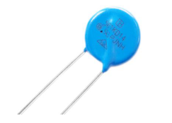
- RoHS compliant 2. Halogen-free series are available. 3. Body size:Ф14mm 4. High peak surge current rating up to 8KA (8/20μs pulse) 5. Operating voltage range:130Vac ~ 550Vac 6. Agency recognition:UL / CSA / VDE/ CQC
◼ Recommended Applications
- Power supply 2. Home appliance 3. Industrial equipment 4. Telecommunication or telephone system 5. Smart meter 6. PLC (Power line communication) 7. Lighting products 8. Photovoltaic industry
◼ Parameters
| 14D-X8 Series | Units | |
|---|---|---|
| AC Voltage Range (Vac) | 130 to 550 | V |
| DC Voltage Range (Vdc) | 170 to 745 | V |
| Peak Current for 8/20µS Current Wave | 8000 | A |
| Energy Range For 10/1000µS Current Wave | 82 to 295 | J |
| Operation Ambient Temperature Range | -40 to +105 | ℃ |
| Storage Temperature Range | -40 to +125 | ℃ |
| Varistor Voltage Range Vn (Vdc) | 200 to 910 | V |
| Voltage Proof | >2500 | V |
| Temperature Cycle (-40~125℃) | 5 | c ycles |
Page 4
◼ Part Number Code
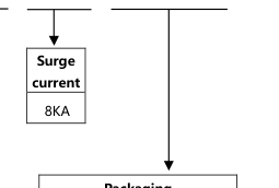
4 7 1 K D 14
J O X8
T R
7
1 2 3 4 5 6
8 9 10 11
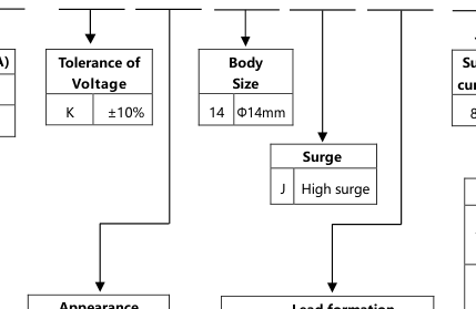
| Varistor Voltage(V1mA) | |
| 471 | 47x101V=470V |
| 561 | 56x101V=560V |
| Packaging | |
| TR | Tape & reel packing (hole pitch:12.7mm) |
| TB | Tape & ammo box packing (hole pitch:12.7mm) |
| ER | Tape & reel packing (hole pitch:15.0mm) |
| EB | Tape & ammo box packing (hole pitch:15.0mm)) |
| Blank | Bulk |
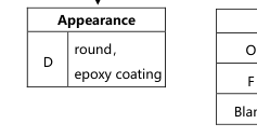
| Lead formation | |
| O | Outside Kink Lead |
| F | In Line Kink Lead |
| Blank | Straight lead |
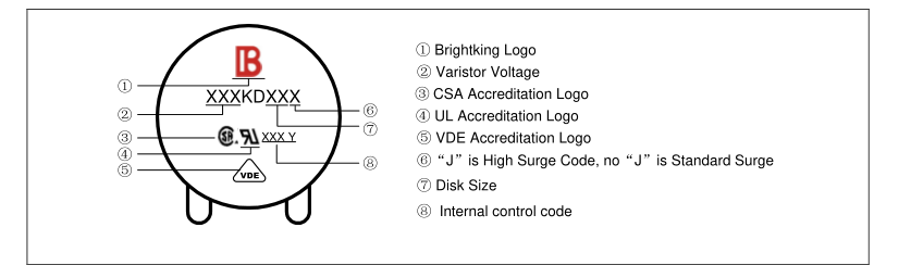
◼ Marking Code
Page 5
◼ Structure and Dimensions
Structure
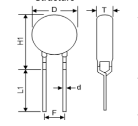
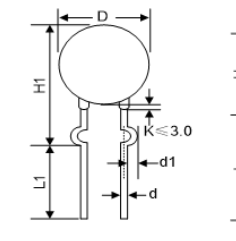
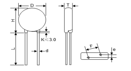
Fig 1. In Line Kink Lead Fig 2. Outside Kink Lead Fig 3. Straight Lead
◼ Dimension Table
| Table 2 Unit: mm | |||||
|---|---|---|---|---|---|
| Model | T (max.) | e | Model | T (max.) | e |
| 201K | 4.3 | 2.0 | 471K | 5.8 | 3.2 |
| 221K | 4.4 | 2.1 | 511K | 6.1 | 3.4 |
| 241K | 4.5 | 2.2 | 561K | 6.4 | 3.6 |
| 271K | 4.6 | 2.4 | 621K | 6.8 | 3.9 |
| 301K | 4.8 | 2.5 | 681K | 7.1 | 4.2 |
| 331K | 5.0 | 2.5 | 751K | 7.2 | 4.3 |
| 361K | 5.2 | 2.7 | 781K | 7.3 | 4.4 |
| 391K | 5.4 | 2.8 | 821K | 7.5 | 4.6 |
| 431K | 5.6 | 3.0 | 911K | 7.5 | 5.0 |
| Table 1 Unit: mm | |
|---|---|
| Symbol | Dimension |
| H (max.) | 21.5 |
| H1 (max.) | 23.0 |
| L (min.) | 20.0 |
| L1 (min.) | 15.0 |
| D (max.) | 18.5 |
| F (±0.8) | 7.5 |
| T (max.) | Table 2 |
| e (±0.8) | Table 2 |
| d (±0.05) | 0.8 |
| d1 (±0.4) | 1.4 |
Page 6
◼ Electrical Characteristics
14D-8KA Series
| Part No . | Varistor Voltage (@ 1mA DC) | Max. Continuous Voltage | Max. Clamping Voltage (8/20μs) | Max. Surge Current (8/20μs) | Rated Power | Max. Energy (10/1000μs) | ||
|---|---|---|---|---|---|---|---|---|
| V1mA | Vac(rms) | Vdc | IP | VP | Imax | P | Wmax | |
| (V) | (V) | (V) | (A) | (V) | (A) | (W) | (J) | |
| 201KD14J-X8 | 200 (180~220) | 130 | 170 | 50 | 340 | 8000 | 0.6 | 82 |
| 221KD14J-X8 | 220 (198~242) | 140 | 180 | 50 | 360 | 8000 | 0.6 | 90 |
| 241KD14J-X8 | 240 (216~264) | 150 | 200 | 50 | 395 | 8000 | 0.6 | 98 |
| 271KD14J-X8 | 270 (243~297) | 175 | 225 | 50 | 455 | 8000 | 0.6 | 116 |
| 301KD14J-X8 | 300 (270~330) | 190 | 250 | 50 | 500 | 8000 | 0.6 | 128 |
| 331KD14J-X8 | 330 (297~363) | 210 | 275 | 50 | 550 | 8000 | 0.6 | 140 |
| 361KD14J-X8 | 360 (324~396) | 230 | 300 | 50 | 595 | 8000 | 0.6 | 158 |
| 391KD14J-X8 | 390(351~429) | 250 | 320 | 50 | 650 | 8000 | 0.6 | 170 |
| 431KD14J-X8 | 430(387~473) | 275 | 350 | 50 | 710 | 8000 | 0.6 | 185 |
| 471KD14J-X8 | 470(423~517) | 300 | 385 | 50 | 775 | 8000 | 0.6 | 205 |
| 511KD14J-X8 | 510(459~561) | 320 | 415 | 50 | 845 | 8000 | 0.6 | 220 |
| 561KD14J-X8 | 560(504~616) | 350 | 460 | 50 | 930 | 8000 | 0.6 | 240 |
| 621KD14J-X8 | 620(558~682) | 385 | 505 | 50 | 1020 | 8000 | 0.6 | 250 |
| 681KD14J-X8 | 680(612~748) | 420 | 560 | 50 | 1120 | 8000 | 0.6 | 260 |
| 751KD14J-X8 | 750(675~825) | 460 | 615 | 50 | 1240 | 8000 | 0.6 | 270 |
| 781KD14J-X8 | 780(702~858) | 485 | 640 | 50 | 1290 | 8000 | 0.6 | 275 |
| 821KD14J-X8 | 820(738~902) | 510 | 670 | 50 | 1355 | 8000 | 0.6 | 280 |
| 911KD14J-X8 | 910(819~1001) | 550 | 745 | 50 | 1500 | 8000 | 0.6 | 295 |
Page 7
◼
Surge Current Standard Waveform
Power Derating Curve
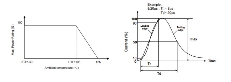
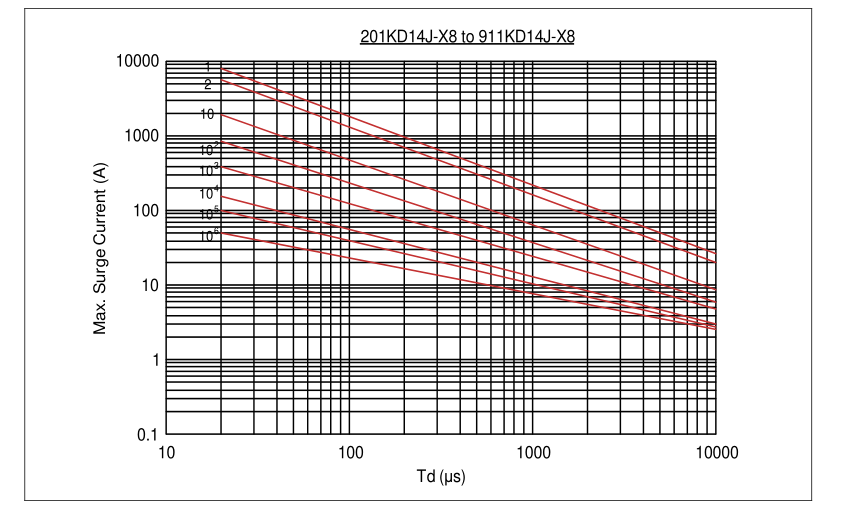
◼ Maximum Surge Current Derating Curve
14D Max. Surge Current Derating Curves
Page 8
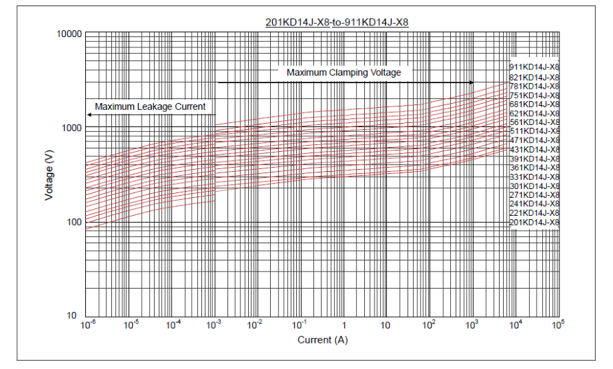
◼ Maximum Leakage Current and Maximum Clamping Voltage Curve
14D Max. Leakage Current and Max. Clamping Voltage Curves
Page 9
◼ Reliability
| Item | Standard | Test conditions / Methods | Specifications | ||
|---|---|---|---|---|---|
| Tensile Strength of Terminals | IEC 60068-2-21 | Gradually apply the specified force and keep the unit fixed for 10±1 sec Terminal diameter Force (mm) (Kg) 0.5<d≦0.8 1.0 0.8<d≦1.25 2.0 | │△V1mA /V1mA│ ≦5% No visible damage | ||
| Bending Strength of Terminals | IEC 60068-2-21 | Hold specimen and apply the force specified below to each lead. Bend the specimen to 90°, then return to the original position. Repeat the procedure in the opposite direction Terminal diameter Force (mm) (Kg) 0.5<d≦0.8 0.5 0.8<d≦1.25 1.0 | │△V1mA /V1mA│ ≦5% No visible damage | ||
| Vibration | IEC 60068-2-6 | Frequency range: 10 ~ 55 Hz Amplitude: 0.75mm or 98 m/s2 Direction: 3 mutually perpendicular directions, 2 hrs each. | │△V1mA /V1mA│ ≦5% No visible damage | ||
| Solderability | IEC 60068-2-20 | 245 ± 3 ℃, 3 ± 0.3 sec | At least 95% of terminal electrode is covered by new solder | ||
| Resistance to Soldering Heat | IEC 60068-2-20 | 260 ± 3 ℃, 10 ± 1 sec | │△V1mA /V1mA│ ≦5% No visible damage | ||
| High Temperature Storage | IEC 60068-2-2 | 125±5℃ x 1000± 24hrs | │△V1mA /V1mA│ ≦5% No visible damage | ||
| Low Temperature Storage | IEC 60068-2-1 | -40±2℃ x 1000± 24hrs | │△V1mA /V1mA│ ≦5% No visible damage | ||
| Damp Heat, Steady State | IEC 60068-2-78 | The test is divided into two groups: a. 40±2℃, 90 ~ 95 % RH, 1344hrs b. 40±2℃, 90 ~ 95 % RH, at 10%Vdc, 1344hrs | │△V1mA /V1mA│ ≦5% No visible damage Insulation Resistance ≧100MΩ | ||
| Rapid Change of Temperature | IEC 60068-2-14 | The conditions shown below shall be repeated 5 cycles。 | │△V1mA /V1mA│ ≦5% No visible damage | ||
| Step | Temperature (℃) | Period (minutes) | |||
| 1 | -40±3 | 30±3 | |||
| 2 | Room temperature | 5±3 | |||
| 3 | 125±3 | 30±3 | |||
| 4 | Room temperature | 5±3 | |||
| High Temp. Load | MIL-STD-202 Method 108 | 105±2℃, 1000±24hrs at VDC or V rms (Max. Continuous Voltage) | │△V1mA /V1mA│≦10 % No visible damage | ||
| 8/20μs Surge Life | IEC 61051-1 | 8/20μs waveform, 10 surge currents, unipolar, interval 30 sec, amplitude corresponding to max. surge current derating curves for 20μs. | │△V1mA /V1mA│≦10 % No visible damage | ||
| 10/1000μs Surge Life | IEC 61051-1 | 10/1000μs waveform, 10 surge currents, unipolar, interval 2 mins, amplitude corresponding to max. surge current derating curves for 1000μs. | │△V1mA /V1mA│≦10 % No visible damage | ||
| Voltage Proof | IEC 61051-1 | Metal balls method, 2500 Vac 1 min | No visible damage | ||
Page 10
◼ Soldering Recommendation
⚫ Wave Soldering Profile
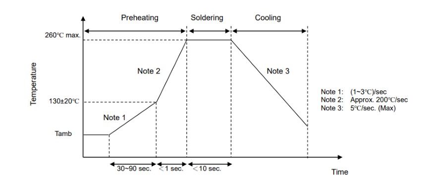
Recommended Reworking Conditions with Soldering Iron ⚫
| Item | Conditions |
|---|---|
| Temperature of Soldering Iron-tip | 360℃ (max.) |
| Soldering Time | 3 sec (max.) |
| Distance from Varistor | 2 mm (min.) |
Page 11
◼
Taping Dimensions
⚫ Straight lead
| P2 P h B W2 H2 W0 W D0 I P1 F W1 P0 t | Symbol | Dimension (mm) |
| P | 25.4±1.0 | |
| P0 | 12.7±1.0 | |
| P1 | 8.95±0.7 | |
| P2 | 12.7±1.3 | |
| F | 7.5±0.8 | |
| h | 0±4 | |
| W | 18.0±1.0 | |
| W0 | 12.0±1.0 | |
| W1 | 9.0±0.5 | |
| W2 | 3.0max | |
| H2 | 20.0±2.0 | |
| I | 2.0max | |
| D0 | 4.0±0.2 | |
| t | 0.6±0.3 | |
| B | 42max |
⚫
In Line Kink Lead
| P2 P h B W2 H0 W0 W D0 I P1 F W1 P0 t | Symbol | Dimension (mm) |
| P | 25.4±1.0 | |
| P0 | 12.7±1.0 | |
| P1 | 8.95±0.7 | |
| P2 | 12.7±1.3 | |
| F | 7.5±0.8 | |
| h | 0±4 | |
| W | 18.0±1.0 | |
| W0 | 12.0±1.0 | |
| W1 | 9.0±0.5 | |
| W2 | 3.0max | |
| H0 | 16.0±1.0 | |
| I | 2.0max | |
| D0 | 4.0±0.2 | |
| t | 0.6±0.3 | |
| B | 42max |
Page 12
⚫ Outside Kink Lead
| P2 P h B W2 H0 W0 W D0 I P1 F W1 P0 t | Symbol | Dimension (mm) |
| P | 25.4±1.0 | |
| P0 | 12.7±1.0 | |
| P1 | 8.95±0.7 | |
| P2 | 12.7±1.3 | |
| F | 7.5±0.8 | |
| h | 0±4 | |
| W | 18.0±1.0 | |
| W0 | 12.0±1.0 | |
| W1 | 9.0±0.5 | |
| W2 | 3.0max | |
| H0 | 16.0±1.0 | |
| I | 2.0max | |
| D0 | 4.0±0.2 | |
| t | 0.6±0.3 | |
| B | 42max |
◼ Quantity
⚫ Bulk Packing
| Packaging Dimensions (Unit: mm) | Voltage Type | Quantity |
|---|---|---|
| In bulk for Terminals Untrimmed Products Max. 130 Max. 165 250 Max. | 201K~331K | 400pcs/bag, 4bags/box |
| 361K~621K | 300pcs/bag, 4bags/box | |
| 681K~911K | 250pcs/bag, 4bags/box | |
| In bulk for Terminals Trimmed Products ax. M 165 66 Max. 252 Max. | 201K~331K | 400pcs/bag, 4bags/box |
| 361K~621K | 300pcs/bag, 4bags/box | |
| 681K~911K | 250pcs/bag, 4bags/box |
Page 13
⚫ Reel Packing
| Packaging Dimensions (Unit: mm) | Voltage Type | P0:12.7mm (pcs/box) | P0:15.0mm (pcs/box) |
|---|---|---|---|
| Tape & Box ax. M 60 Max. 250 340 Max. | 201K-241K | 750 | 500 |
| 271K-331K | 600 | 500 | |
| 361K-621K | 500 | 400 | |
| 681K-751K | 400 | 400 | |
| 781K-911K | 350 | 300 | |
| Tape & Reel Max. 60 Max. 365 365 Max. 55 Max. 30±1 Φ365 Max. | 201K-331K | 1000 | 750 |
| 361K-621K | 750 | 600 | |
| 681K-751K | 500 | 600 | |
| 781K-911K | 400 | 500 |
Page 14
Legal Disclaimer
YAGEO, its distributors and agents (collectively, “YAGEO”), hereby disclaims any and all liabilities for any errors, inaccuracies or incompleteness contained in any product related information, including but not limited to product specifications, datasheets, pictures and/or graphics. YAGEO may make changes, modifications and/or improvements to product related information at any time and without notice.
YAGEO makes no representation, warranty, and/or guarantee about the fitness of its products for any particular purpose or the continuing production of any of its products. To the maximum extent permitted by law, YAGEO disclaims (i) any and all liability arising out of the application or use of any YAGEO product, (ii) any and all liability, including with out limitation special, consequential or incidental damages, and (iii) any and all implied warranties, including warranties of fitness for a particular purpose, non -infringement and merchantability.
YAGEO products are designed for general purpose applications under normal operation and usage conditions. Please contact YAGEO for the applications listed below which require especially high reliability for the prevention of defects which might directly cause damage to the third party's life, body or property: Aerospace equipment (artificial satellite, rocket, etc.), Atomic energy-related equipment, Aviation equipment, Disaster prevention equipment, crime prevention equipment, Electric heating apparatus, burning equipment, Highly public information network equipment, data-processing equipment , Medical devices, Military equipment, Power generation control equipment, Safety equipment, Traffic signal equipment, Transportation
equipment and Undersea equipment, or for any other application or use in which the failure of YAGEO products could result in personal injury or death, or serious property damage. Particularly YAGEO Corporation and its affiliates do not recommend the use of commercial or automotive grade products for high reliability applications or manned space flight.
Information provided here is intended to indicate product specifications only. YAGEO reserves all the rights for revising thi s content without further notification, as long as products are unchanged. Any product change will be announced by PCN.