
1401 VISHAY
Document overview
- Manufacturer or author: Provided By www.digicamel.com(free datasheet download site)
- PDF pages: 1
Technical content
www.vishay.com 119 1401 Vishay Foil Resistors Document Number: 63037 Revision 31-Jul-02 THROUGH HOLE
- GERMANY +49.9287.710 FAX: +49 9287.70435
- SINGAPORE +65.788.6668 FAX: +65.788.0988
- UK +44 191 514 8237 FAX: +44 1953 457 722
- USA +1 610 407-4800 FAX: +1 610 640-9081 Bulk Metal® Foil Technology
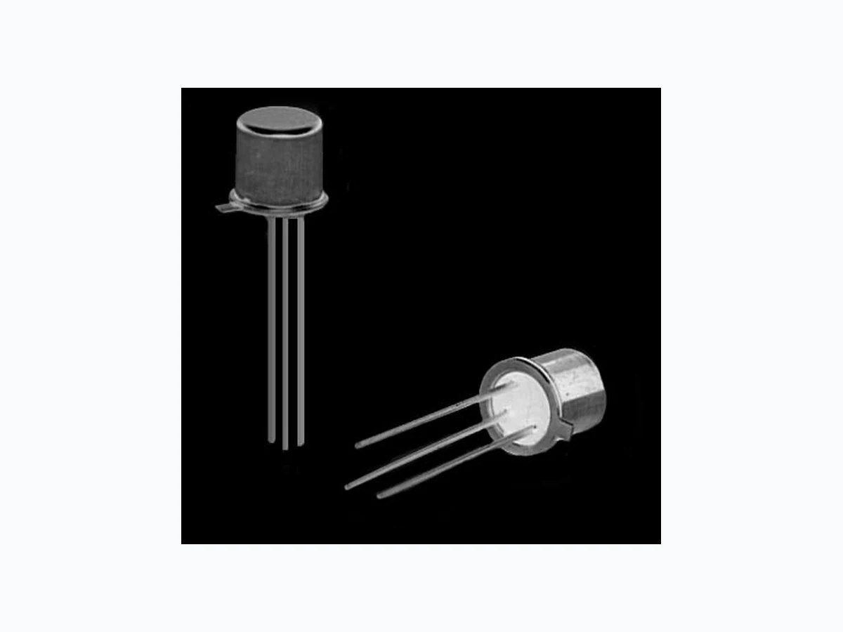
3 Pin Transistor Outline Hermetic Resistor Network
The three pin TO-18 package is suitable for single resistor hermetic packaging with case and lid grounded for electrical isolation. This unique package may also be used to provide a voltage divider, but the user is cautioned that the center tap must go to ground. Review data sheet “7 Technical Reasons to Specify Bulk Metal® Foil Resistor Networks.” 3 pins on a 0.100" pin circle– pin 3 case grounded. FIGURE 1 - STANDARD DIMENSIONS in inches (millimeters) ORDERING INFORMATION - 1401 PARTS Networks are built to your requirements. Send your schematic and electrical requirements to the Applications Engineering Department. (See data sheet “Network Worksheet.”) A unique part number will be assigned which defines all aspects of your network. VISHAY CHIP MAXIMUM POWER RATING MODEL NUMBER CAPACITY (WATTS) @ +70°C V15X5 - 1 chip V15X5 - 1 chip 1401 and
0.15 Watt
0.036 –0.046 (0.91 –1.17) DIAMETER 0.178 –0.195 (4.52 –4.95) 0.500 (12.7) 0.209 –0.230 (5.31 –5.84) DIAMETER MAXIMUM 0.200 (5.08) 0.016 –0.021 (0.41 –0.48)
3 LEADS
0.028 –0.048 (0.71 –1.22) 0.100 (2.54) CASE GROUNDED 45° NOTES: 1. These networks utilize Vishay Bulk Metal® Foil resistor chips V5X5 and V15X5 or VTF15X10 Thin Film chips. 2. The V5X5 and V15X5 chips have maximum resistance values of 10K and 33K respectively in Bulk Metal® Foil and 500K in VTF15X5 Thin Film chips. FIGURE 2 - SAMPLE CIRCUIT DESIGNS AND CHIP LAYOUTS NOTE: Usable area is represented by the dotted lines— a cross 0.150 Inches x 0.150 Inches with arm width of 0.05 Inches. Illustrations not to scale. Chips shown undersize for clarity. Drawing view is from the top looking down into the package. CASE CASE ONE RESISTOR CASE GROUNDED DIVIDER CENTER TAP GROUNDED (VIEWED FROM BOTTOM) Product may not be to scale MINIMUM