
12PT_18 NELLSEMI
Document overview
- Manufacturer or author: Provided By www.digicamel.com(FREE DATASHEET DOWNLOAD SITE)
- PDF pages: 7
Technical content
A A G K Page 1 of 7 Sensitive and Standard SCRs, 12A SYMBOL IT(RMS)RMS on-state current full sine wave ITSMNon repetitive surge peak on-state current (full cycle, T initial = 25°C)j A 2I t2I t Value for fusing 98 2A s dI/dtCritical rate of rise of on-state current 50 IGMPeak gate current PG(AV)Average gate power dissipation TstgStorage temperature range Operating junction temperature range - 40 to + 150 - 40 to + 125 ºC A/µs A A W UNITV ALUE 140 145 F =50 Hz F =60 Hz t = 20 ms t = 16.7 ms t = 10 msp F = 60 Hz T =125ºCj T = 125ºCj T = 125ºCj T = 20 µsp Tj ABSOLUTE MAXIMUM RATINGS PARAMETER TEST CONDITIONS Main Features Symbol Value Unit IT(RMS) V /VDRM RRM IGT 12 A V mA0.2 to 15 600 to 1000
DESCRIPTION
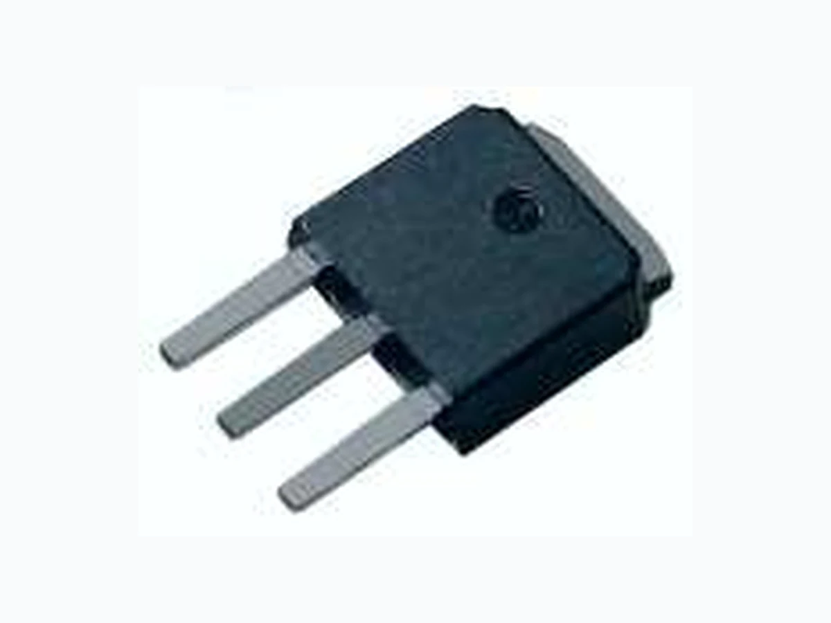
(180° conduction angle ) Average on-state current (180° conduction angle) IT(AV) 8 A A K A G TO-220AB (Non-lnsulated) I = 2xl , t ≤100nsG GT r K A G TO-220AB (lnsulated) (12PTxxA) (12PTxxAI) www.nellsemi.com T =105°CC T =90°CC TO-251-4R/TO-252-4R/TO-220AB/TO-263 TO-220AB insulated TO-251-4R/TO-252-4R/TO-220AB/TO-263 TO-220AB insulated T =105°CC T =90°CC Available either in sensitive or standard gate triggering levels, the 12A SCR series is suitable to fit all modes of control found in applications such as overvoltage crowbar protection, motor control circuits in power tools and kitchen aids, inrush current limiting circuits, capacitive discharge ignition and voltage regulation circuits. Available in through-hole or surface-mount packages, they provide an optimized performance in a limited space. 2TO-263 (D PAK) (12PTxxH) 3(G) 1(K) 2(A) 12PT Series RoHS RoHS TO-251-4R (I-PAK) TO-252-4R (D-PAK) (12PTxxF) (12PTxxG) K A G A K A G A
V = 12 V, R = 33ΩD L V = V , R = 3.3K ΩD DRM L I = 500 mA, gate openT I = 1.2 IG GT V = 67% V gate openD DRM , 0.2 200 0.85 mA V V mA V/µs I = 24A, t = 380 µsTM P T = 125°Cj T = 25°Cj T = 125°Cj V µA STANDARD ELECTRICAL SPECIFICATIONS TEST CONDITIONS SYMBOL V = VDRM RRM 1.6 Min. Max. Max. Min. Max. Min. Max. Max. Max. DYNAMIC CHARACTERISTICS tgt tq 2.0 µS UNITV ALUE SYMBOL PARAMETER I = 40A, V = V (Max.),TM D DRM I = 0.1 A, dI /dt = 5A/ μs, T = 25°CG G J VGT 0.5 T 1.3 T = 125°Cj Max. 30 30 60 Vto Threshold voltage V Rd T = 125°Cj Max. 30 mΩ mA T = 25°Cj T = 125°Cj Dynamic resistance 12PTxxxx-S Unit IGT VGD mA dV/dt VTM IDRM IRRM mA IH V = 12 V, R = 140ΩD L V = V , R = 3.3K Ω, R =220 ΩD DRM L GK I = 10 µARG I = 50 mA R = 1 KΩT , GK V = 67% V R = 220ΩD DRM GK , 0.1 0.85 µA V V V/µs I = 24A, t = 380 µsTM P T = 125°Cj T = 25°Cj T = 125°Cj V µA SENSITIVE ELECTRICAL CHARACTERISTICS TEST CONDITIONS SYMBOL V = V R = 220 ΩDRM RRM, GK 1.6 Max. Max. Min. Max. Min. Max. Max. Max. VGT 0.8 200 T = 125°Cj Vto Threshold voltage V Rd T = 125°Cj Max. 30 mΩ V T = 25°Cj T = 125°Cj Dynamic resistance VRG Min. IL I = 1 mA R = 1 KΩG , GK Max. mA Page 2 of 7www.nellsemi.com turn-on time TEST CONDITIONS Min. Typ. Max. -- µSCommutated V = 67% V , I = 20A, D DRM TM V = 25V , R = 100Ω, dI /dt = 30A/ μs,R GK TM dV /dt = 50V/ μs, T = 125°C D J turn-off time Gate-controlled 12PT Series RoHS RoHS (T = 25 ºC unless otherwise specified)J (T = 25 ºC unless otherwise specified)J
Page 3 of 7www.nellsemi.com
ORDERING INFORMATION
ORDERING TYPE MARKING PACKAGE WEIGHT ,BASE Q TY DELIVERY MODE TO-220AB 2.0g 50 Tube 12PTxxAI-y 12PTxxAI-y 2.3g 50 Tube 12PTxxF-y 12PTxxF-y TO-251-4R (I-PAK) 0.40g 80 12PTxxG-y 12PTxxG-y 0.38g 80 TubeTO-252-4R (D-PAK) TO-220AB (insulated) Tube Note: xx = voltage, y = sensitivity PRODUCT SELECTOR PART NUMBER VOL T AGE (xx) SENSITIVITY 600 V 200 µA 1000 V 12PTxxA-S/12PTxxAl-S 12PTxxF-S 12PTxxG-S V VV V 800 V V V PACKAGE TO-220AB D-PAK VV V VV V V V V 12PTxxA-T/12PTxxAl-T VV V V V V V V V V V V 12PTxxA/12PTxxAl 12PTxxF-T 12PTxxF 12PTxxG-T 12PTxxG D-PAK D-PAK I-PAK I-PAK I-PAK TO-220AB TO-220AB 0.5~5 mA 2~15 mA 200 µA 2~15 mA 200 µA 0.5~5 mA 2~15 mA 12PTxxH-S 200 µA D²-PAK D²-PAK D²-PAK 0.5~5 mA 2~15 mA V V V V V V V V V 12PTxxH-T 12PTxxH 12PTxxH-y 12PTxxH-y 50 Tube2.0gTO-263(D²-PAK) THERMAL RESISTANCE Rth(j-c) Junction to case (DC) Rth(j-a) Junction to ambient (DC) 1.3 °C/W °C/W UNITV ALUESYMBOL Parameter IPAK/DPAK/TO-220AB/TO-263 D-PAK I-PAK TO-220AB, TO-220AB insulated 4.6 2S = 0.5 cm TO-220AB insulated S=Copper surface under tab D²PAK2S = 1 cm 100 12PT Series RoHS RoHS 0.5~5 mA
ORDERING INFORMATION SCHEME SCR series Package type Current V oltage Code I Sensitivity GT A = TO-220AB (non-insulated) AI = TO-220AB ( insulated) 12 = 12A, IT(RMS) T = 0.5~5 mA
12 PT 06 - S
06 = 600V F = TO-251-4R (I-PAK) G = TO-252-4R (D-PAK) 08 = 800V Blank = 2~15 mA 10 = 1000V S = 70~200 µA H = TO-263 (D²PAK) Page 4 of 7www.nellsemi.com Fig.3 Average and DC on-state current versus ambient temperature (DPAK) Fig.4 Relative variation of thermal impedance junction to case versus pulse duration 2.5 2.0 1.5 1.0 0.5 0.0 0 25 50 75 100 125 1E+0 0.1 0.2 0.5 1.0 I (AV)(A)T Fig.1 Maximum average power dissipation versus average on-state current Fig.2 Average and DC on-state current versus case temperature P(W) 0 1 2 4 5 6 0 25 50 75 100 125 I (A)T(AV) 1E+11E+21E+3 K=[Z th(j-c) /Rth(j-c) ] α=180° 360° αI (A)T(AV) 3 7 8 9 T (°C)case Insulated TO-220AB TO-251-4R/TO-252-4R TO-263/TO-220AB Device mounted on F R4 with Recommended pad layout T (°C)amb α=180° DPAK DC D²PAK 3.0 t (s)p 12PT Series RoHS RoHS α=180° DC
0.0 0.2 0.4 0.6 0.8 1.6 0.01 0.10 1.00 Fig.5 Relative variation of thermal impedance Junction to ambient versus pulse duration Fig.6 Relative variation of gate trigger and holding current versus junction temperature for I =200 µA GT -401E+11E-2 1E-1 1E+0 1E+2 5E+2 1.0 1.2 1.4 1.8 2.0 -20 0 20 40 60 80 100 120 140 I ,I ,I [T ] / I ,I ,I [Tj=25°C]GT H L j GT H LK=[Z th(j-a) /Rth(j-a) ] t (s)p D²PAK TO-220AB/IPAK Device mounted on F R4 with Recommended pad layout DPAK IGT l & I LH R =1KΩGK T (°C)j (DANK) Page 5 of 7www.nellsemi.com 0.1 0 200 400 1.0 Fig.9 Relative variation of dV/dt immunity versus gate-cathode resistance 0.0 0.5 1.0 1.5 0.0 0.2 4.0 5.0 -20 0 6020-40 40 3.5 4.5 100 14080 120 0.4 dV/dt[R ] / dV/dt[R =220Ω]GK GK Fig.7 Relative variation of gate trigger and holding current versus junction temperature Fig.8 Relative variation of holding current versus gate-cathode resistance (typical values) dV/dt[C ] / dV/dt[R =220Ω]GK GK 0.6 0.8 1.0 1.2 1.4 1.6 1.8 2.0 2.2 2.4 1E-2 1E-1 1E+0 1E+1 600 800 1000 1200 10.0 25 7550 125 150100 2.0 2.5 3.0 IH[RGK] / IH[RGK=1KΩ]I ,I ,I [Tj] / I ,I ,I [Tj=25 °C]GT H L GT H L 3.0 2.5 2.0 1.5 1.0 0.5 0.0 (Typical values) Fig.10 Relative variation of dV/dt immunity versus gate-cathode capacitance (typical values) for I =200µA GT 5mA & 15mA Series IGT l & I LH T (°C)j R (KΩ)GK Tj=125 °C V =0.67 X VD DRM R (KΩ)GK C (nF)GK V =0.67 X VD DRM Tj=125 °C R =220ΩGK 3.5 4.0 200µA Series Tj=25 °C 12PT Series RoHS RoHS
I (A)STM Fig.11 Surge peak on-state current versus number of cycles Fig.12 Non-repetitive surge peak on-state current and corresponding values of l²t versus 0.0110 1 100 1000 100 0.10 1.00 10.00 100 1000 I (A),I²t(A²s)TSM t =10msp One cycle Non repetitive T initial=25 °Cj Number of cycles 110 120 130 140 150 Repetitive Tc=105 °C I²t ITSM Tj inital=25 °C t (ms)p dI/dt Iimitation 2000 sinusoidal pulse width Page 6 of 7www.nellsemi.com Fig.13 On-state characteristics (maximum values) Fig.14 Thermal resistance junction to ambient versus copper surface under tab (D²PAK) 100 200 0 2 4 6 8 10 12 14 16 18 20 100 I (A)TM Rth(j-a)( °C/W) VTM(V) Tj=25 °C Tj=max Tjmax Vt0=0.85V Rd=30mΩ 4.5 5.0 S(cm²) Epoxy printed circuit board FR4 copper thickness = 35µm DPAK D²PAK Case Style 2.87 (0.113) 2.62 (0.103) 9.40 (0.370) 9.14 (0.360) 10.54 (0.415) MAX. 16.13 (0.635) 15.87 (0.625) PIN 4.06 (0.160) 3.56 (0.140) 1.45 (0.057) 1.14 (0.045) 2.67 (0.105) 2.41 (0.095) 2.65 (0.104) 4.95 (0.195) 0.90 (0.035) 0.70 (0.028) 3.91 (0.154) 3.74 (0.148) K G A 4.70 (0.185) 4.44 (0.1754) 1.39 (0.055) 1.14 (0.045) 3.68 (0.145) 3.43 (0.135) 8.89 (0.350) 8.38 (0.330) 29.16 (1.148) 28.40 (1.118) 14.22 (0.560) 13.46 (0.530) 0.56 (0.022) 0.36 (0.014) 2.79 (0.110) 2.54 (0.100) 15.32 (0.603) 14.55 (0.573) TO-220AB 3(G) 1(K) 2(A) 12PT Series RoHS RoHS
Page 7 of 7www.nellsemi.com Case Style 3(G) 1(K) 2(A) 2TO-263(D PAK) 2.79 (0.110) 0.36 (0.014) 2.79 (0.110) 2.29 (0.090) 1.40 (0.055) 1.19 (0.047) 0 to 0.254 (0 to 0.01) 1.40 (0.055) 1.14 (0.045) 4.83 (0.190) 4.06 (0.160) 10.45 (0.411) 9.65 (0.380) 6.22 (0.245) 9.14 (0.360) 8.13 (0.320) 15.00 (0.591) 0.940 (0.037) 0.686 (0.027) 2.67 (0.105) 2.41 (0.095) 5.20 (0.205) 4.95 (0.195) 15.85 (0.624) 3.56 (0.140) 0.53 (0.021) K G A A 12PT Series RoHS RoHS TO-252-4R (D-PAK) TO-251-4R (I-PAK) K G A A K G A A