

 Download PDF
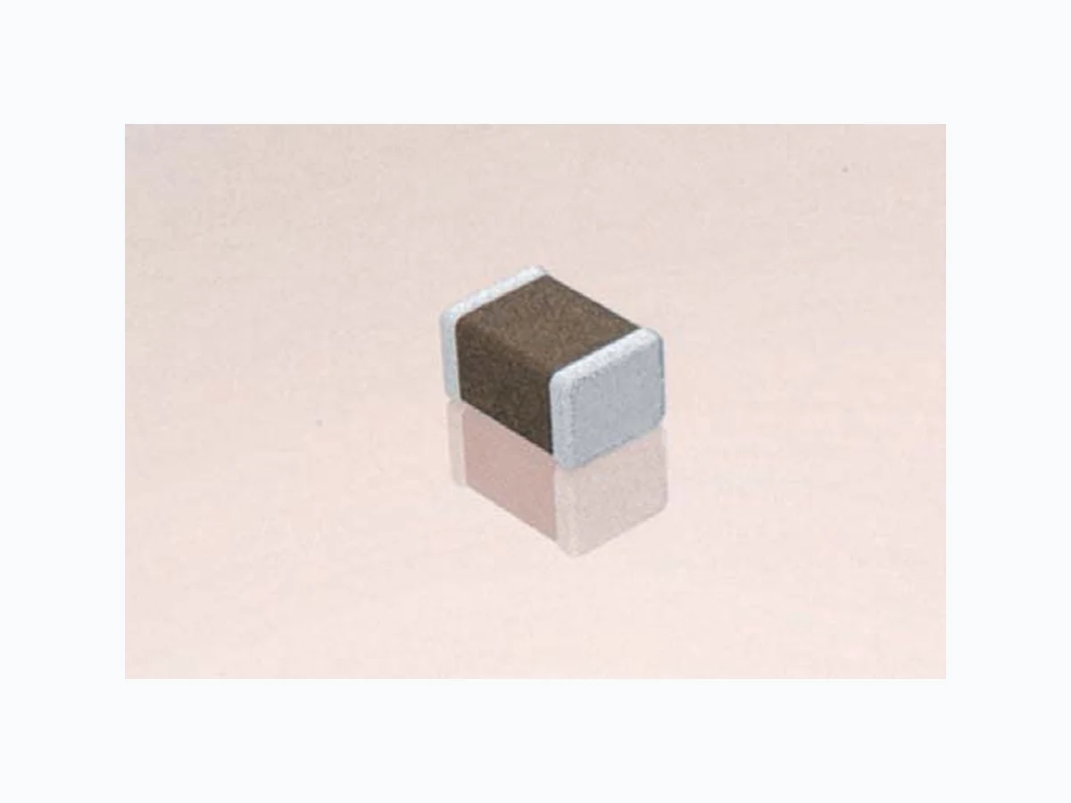
1210ZG226ZAT2A AVX
Document overview
- Manufacturer or author: Provided By digicamel.com
- PDF pages: 3
Technical content
Y5V formulations are for general-purpose use in a limited temperature range. They have a wide temperature characteristic of +22% –82% capacitance change over the operating temperature range of –30°C to +85°C. These characteristics make Y5V ideal for decoupling applications within limited temperature range. 0805 Size (L" x W") Voltage 6.3V = 6 10V = Z 16V = Y 25V = 3 50V = 5 G Dielectric Y5V = G 104 Capacitance Code (In pF) 2 Sig. Digits + Number of Zeros Z Capacitance Tolerance Z = +80 –20% A Failure Rate A = Not Applicable T Terminations T = Plated Ni and Sn Packaging 2 = 7" Reel 4 = 13" Reel A Special Code A = Std. Product PART NUMBER (see page 2 for complete part number explanation) % /H9004 Capacitance +20 +10 -55 -35 -15 +5 +25 +45 +65 +85 +105 +125 Temperature °C Temperature Coefficient -60 -50 -40 -30 -20 -10 -70 -80 /H9004 c/c (%) +20 +40 % DC Bias Voltage Capacitance Change vs. DC Bias Voltage -60 -40 -20 -100 -80 20 40 60 80 100 Insulation Resistance (Ohm-Farads) 1,000 10,000 100 0 +20 +30 +40 +60 +50 +70 +80 +90 Temperature °C Insulation Resistance vs. Temperature |Z| (Ohms) 10,000 1,000 10,000 Frequency (Hz) 0.1 /H9262F - 0603 Impedance vs. Frequency 100 0.01 0.1 100,000 1,000,000 10,000,000 |Z| (Ohms) 1,000 10,000 Frequency (Hz) 0.22 /H9262F - 0805 Impedance vs. Frequency 100 0.01 0.1 100,000 1,000,000 10,000,000 |Z| (Ohms) 1,000 10,000 Frequency (Hz) 1 /H9262F - 1206 Impedance vs. Frequency 100 0.01 0.1 100,000 1,000,000 10,000,000
Specifications and Test Methods Parameter/Test Y5V Specification Limits Measuring Conditions Operating Temperature Range -30ºC to +85ºC Temperature Cycle Chamber Capacitance Within specified tolerance ≤ 5.0% for ≥ 50V DC rating Freq.: 1.0 kHz ± 10% Dissipation Factor ≤ 7.0% for 25V DC rating Voltage: 1.0Vrms ± .2V ≤ 9.0% for 16V DC rating For Cap > 10 μF, 0.5Vrms @ 120Hz ≤ 12.5% for ≤ 10V DC rating Insulation Resistance 100,000MΩ or 500MΩ - μF, Charge device with rated voltage for whichever is less 120 ± 5 secs @ room temp/humidity Charge device with 300% of rated voltage for Dielectric Strength No breakdown or visual defects 1-5 seconds, w/charge and discharge current limited to 50 mA (max) Appearance No defects Deflection: 2mm Capacitance Test Time: 30 seconds Resistance to Variation ≤ ±30% Flexure Dissipation Meets Initial Values (As Above)Stresses Factor Insulation ≥ Initial Value x 0.1Resistance Solderability ≥ 95% of each terminal should be covered Dip device in eutectic solder at 230 ± 5ºC with fresh solder for 5.0 ± 0.5 seconds Appearance No defects, <25% leaching of either end terminal Capacitance Variation ≤ ±20% Dip device in eutectic solder at 260ºC for 60Dissipation Meets Initial Values (As Above) seconds. Store at room temperature for 24 ± 2Resistance to Factor hours before measuring electrical properties.Solder Heat Insulation Meets Initial Values (As Above)Resistance Dielectric Meets Initial Values (As Above)Strength Appearance No visual defects Step 1: -30ºC ± 2º 30 ± 3 minutes Capacitance Variation ≤ ±20% Step 2: Room Temp ≤ 3 minutes Dissipation Meets Initial Values (As Above) Step 3: +85ºC ± 2º 30 ± 3 minutesThermal FactorShock Insulation Meets Initial Values (As Above) Step 4: Room Temp ≤ 3 minutesResistance Dielectric Meets Initial Values (As Above) Repeat for 5 cycles and measure after Strength 24 ±2 hours at room temperature Appearance No visual defects Capacitance Variation ≤ ±30% Dissipation ≤ Initial Value x 1.5 (See Above)Load Life Factor Insulation ≥ Initial Value x 0.1 (See Above)Resistance Dielectric Meets Initial Values (As Above)Strength Appearance No visual defects Capacitance Variation ≤ ±30% Load Dissipation ≤ Initial Value x 1.5 (See above)Humidity Factor Insulation ≥ Initial Value x 0.1 (See Above)Resistance Dielectric Meets Initial Values (As Above)Strength Charge device with twice rated voltage in test chamber set at 85ºC ± 2ºC for 1000 hours (+48, -0) Remove from test chamber and stabilize at room temperature for 24 ± 2 hours before measuring. Store in a test chamber set at 85ºC ± 2ºC/ 85% ± 5% relative humidity for 1000 hours (+48, -0) with rated voltage applied. Remove from chamber and stabilize at room temperature and humidity for 24 ± 2 hours before measuring. 1mm/sec 90 mm
PREFERRED SIZES ARE SHADED SIZE 0201 0402 0603 0805 1206 1210 Soldering Reflow Only Reflow Only Reflow Only Reflow/Wave Reflow/Wave Reflow Only Packaging All Paper All Paper All Paper Paper/Embossed Paper/Embossed Paper/Embossed WVDC 6.3 10 16 25 50 10 16 25 50 10 16 25 50 10 16 25 50 10 16 25 50 Cap 820 (pF) 1000 A 2200 A
4700 A C
Cap 0.010 A A C C G (μF) 0.022 A C C G
0.047 A C G G
0.10 C G J K
0.22 GG NN
0.47 GK N M
1.0 G G N N N
2.2 NN MM
4.7 NP N
10.0 QQ Q Q
22.0 QX 47.0 WVDC 6.3 10 16 25 50 10 16 25 50 10 16 25 50 10 16 25 50 10 16 25 50 SIZE 0201 0402 0603 0805 1206 1210 Letter A C E G J K M N P Q X Y Z PAPER EMBOSSED L/H17010 /H17010 /H17010 /H17010 W /H17010/H17010 /H17010 /H17010 T t