
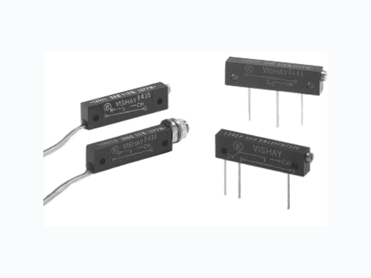
1202 VISHAY
Document overview
- Manufacturer or author: Provided By www.digicamel.com(free datasheet download site)
- PDF pages: 6
Technical content
Document Number: 63055 For any ques tions, contact: foil@vishay.com www.vishay.com Revision: 13-Nov-07 1 1202 Vishay Foil Resistors Bulk Metal® Foil Technology Precision Trimming Potentiometers, 1 1/4 Inch Rectilinear, RJ12 Style, Designed to Meet or Exceed The Requirements of MIL-PRF-22097, Char. F Note 1. See Figures 1 and 2.
FEATURES
- Temperature coefficient of resistance (TCR): ± 10 ppm/°C maximum3) (- 55 °C to + 150 °C ref. at + 25 °C); through the wiper 4); ± 25 ppm/°C
- Load life stability: 0.1 % typical ΔR, 0.5 % maximum ΔR under full rated power at + 85 °C for 2000 h
- Settability: 0.05 % typical; 0.1 % maximum
- Setting stability: 0.1 % typical; 0.5 % maximum, ΔSS
- Power rating: 0.5 W at + 85 °C
- Resistance range: 2 Ω to 20 kΩ
- “O“-ring prevents ingress of fluids during any board cleaning operation
- Electrostatic discharge: above 25 000 V
- Terminal finishes available: gold plated Notes † Under full rated power of 0.5 W at + 85 °C. Refer to page 4 for footnotes. * Pb containing terminations are not RoHS compliant, exemptions may apply TABLE 1 - MODEL SELECTION† MODEL TERMINATION STYLE AVERAGE WEIGHT (g) POWER RATING at + 85 °C AMBIENT NO. OF TURNS 1202 P-In line PC pins 2.5
0.5 W 25 ± 2
Y -staggered PC pins1) 2.5 L-flexible wire leads 3.3 LB-flexible wire leads with bushings 5.1 TABLE 2 - VALUES VS. TOLERANCES STANDARD RESISTANCE VALUES (in Ω) STANDARD TOLERANCES 20, 50, 100, 200, 250, 500, 1K, 2K, 5K, 10K, 20K 5 %, 10 % Available Pb-free RoHS* COMPLIANT TABLE 3 - 1202 (RJ12) SERIES ELECTRICAL SPECIFICATIONS Temperature Coefficient of Resistance (TCR) end-to-end3) ± 10 ppm/°C maximum (- 55 °C to + 25 °C) ± 10 ppm/°C maximum (+ 25 °C to + 150 °C) 2 Ω, 5 Ω, 10 Ω, 20 Ω through the wiper ± 20 ppm/°C ± 25 ppm/°C Stability load life at 2000 h load life at 10 000 h† 0.1 % typical ΔR; 0.5 % maximum ΔR 0.1 % typical ΔR; 1.0 % maximum ΔR Power Rating5) 0.5 W at + 85 °C Settability 0.05 % typical; 0.1 % maximum Setting Stability 0.1 % typical; 0.5 % maximum ΔSS Contact Resistance variation - CRV (noise) 3 Ω typical; 10 Ω maximum Hop-off 0.25 % typical; 1.0 % maximum High-Frequency Operation Rise time Inductance Capacitance to 100 MHz 10 ns at 1 kΩ 0.08 µH typical 0.5 pF typical Operating Temperature Range - 55 °C to + 150 °C TABLE 4 - MECHANICAL SPECIFICATIONS Adjustment Turns 25 ± 2 Case Material Glass fortified diallyl-phthalate (DAP); black Mechanical Stops Wiper idles - no discontinuity Shaft Torque 8 oz. in. maximum; 3 oz. in. typical Internal Terminations All welded - no flux Backlash 0.05 % typical
Vishay Foil Resistors Bulk Metal® Foil Technology Precision Trimming Potentiometers, 1 1/4 Inch Rectilinear, RJ12 Style, Designed to Meet or Exceed The Requirements of MIL-PRF-22097, Char. F www.vishay.com For any questions, contact: foil@vishay.com Document Number: 63055
2 Revision: 13-Nov-07
FIGURE 1 - SCHEMATIC AND DIMENSIONS in inches (millimeters) TOLERANCES Note 1. Pin leads are gold plated nickel which are solderable or weldable. STANDARD MARKING ILLUSTRATION 0.125" (3.18 mm) A 0.070" (1.78 mm) C 0.700" (17.78 mm) C 0.235" (5.97 mm) C 0.260" (6.60 mm) C 0.125" (3.18 mm) A 0.093" (2.36 mm) DIA (A) 2 Mtg. Holes Slot 0.025" (0.64 mm) W x Schematic 0.125" (3.18 mm) DIA (A) 0.195" (4.95 mm) A 0.325" (8.26 mm) A 0.500" (12.70 mm) C 0.028" (0.71 mm) DIA (B)
3 Pin Type Leads
(In-Line Pins)1) 0.125" (3.18 mm) A 0.070" (1.78 mm) C 0.300" (7.62 mm) C 0.235" (5.97 mm) C 0.265" (6.73 mm) C 0.125" (3.18 mm) A 0.093" (2.36 mm) DIA (A) 2 Mtg. Holes Slot 0.025" (0.64 mm) W x Schematic CW 0.125" (3.18 mm) DIA (A) 0.195" (4.95 mm) A 0.325" (8.26 mm) A 0.500" (12.70 mm) C 0.028" (0.71 mm) DIA (B) 0.100" (2.54 mm) C 1 2 3 1202Y (Staggered Pins)1) Model No., Resistance Value, Tolerance, TCR Schematic CW Vishay Date Code
Document Number: 63055 For any ques tions, contact: foil@vishay.com www.vishay.com Revision: 13-Nov-07 3 1202 Bulk Metal® Foil Technology Precision Trimming Potentiometers, 1 1/4 Inch Rectilinear, RJ12 Style, Designed to Meet or Exceed The Requirements of MIL-PRF-22097, Char. F Vishay Foil Resistors FIGURE 2 - SCHEMATIC AND DIMENSIONS in inches (millimeters) TOLERANCES Standard marking shown on previous page. 0.125" (3.18 mm) DIA (A) G Y R 0.195" (4.95 mm) A 0.325" (8.26 mm) A Schematic R GY CW
3 Color Coded Leads—
# 30 AWG Teflon Coated Insulated Stranded Wire 11.50" (292.10 mm) Min. Length G Y R 0.125" (3.18 mm) A 0.070" (1.78 mm) C 0.235" (5.97 mm) C 2 Mtg. Holes Slot 0.025" (0.64 mm) W x 1202L (Flexible Leads) # 30 AWG Teflon Coated Insulated Stranded Wire 11.50" (292.10 mm) Min. Length G Y R Schematic R GY CW 0.125" (3.18 mm) C 0.042" (1.07 mm) B 0.325" (8.26 mm) A 0.125" (3.18 mm) A 0.093" (2.36 mm) DIA (A) 2 Mtg. Holes # 10 - 32 N.C. - 2 Rubber Gasket Lockwasher Hexnut G Y R 0.280" (7.11 mm) B 0.195" (4.95 mm) A 0.400" (10.16 mm) A 0.300" (7.62 mm) A 0.235" (5.97 mm) A Slot: 0.025" (0.64 mm) W x 1202LB (Panel Mounted) FIGURE 3 - POWER DERATING CURVE - 75 - 50 - 25 0 + 25 + 50 + 75 + 100 + 125 + 150 + 175 Ambient Temperature °C + 85 °C+ 100 + 75 + 50 + 25 Percent of Rated Power
Vishay Foil Resistors Bulk Metal® Foil Technology Precision Trimming Potentiometers, 1 1/4 Inch Rectilinear, RJ12 Style, Designed to Meet or Exceed The Requirements of MIL-PRF-22097, Char. F www.vishay.com For any questions, contact: foil@vishay.com Document Number: 63055
4 Revision: 13-Nov-07
- Preferred Termination style fo r current 1-1/4 inch rectilinear trimmers (staggered PC pins present a sturdier mounting arrangement for shock, vibration, and impact situations). 2. 10 W at ± 5 % available on special order. 3. Maximum TCR applies to the 3 σ (sigma) limit or 99.73 % of a production lot. (Measured end-to-end with wiper off the element.) 4. Measurements of TCR through the wiper are influenced more by setting stability and the percentage of the total resistance in use (at the wiper) than by fundamental resistance change due to temperature alone. The parameter shown in Table 3 is a 2 σ distribution typifying the behavior of the device when used with 40 % or more of the total resistance in use. 5. Derated linearly from full power at + 85 °C to zero (0) W at + 150 °C. See Figure 3 in this data sheet. 6. All ΔR’s are measured to the tolerance specified + 0.01 Ω. 7. Whichever is greater. 8. Load-Life test performed at nominal rated power, 0.5 W, at + 85 °C. Special Available Options: Special marking Special lengths for lead wires (L, LB Style) Hooked leads Alternate bushing and PC combinations Power conditioning and screening operations VISHAY TRIMMERS ARE INSPECTED 100 % for: Short-time overload (6.25 x rated power for 5 s on; and for 30 s off - 3 cycles) Immersion Resistance tolerance check End resistance Visual-mechanical Dynamic tests for continuity, CRV By Sample for: T C R D W V TABLE 5 - COMPARISON MIL-PRF-22097/2 CHARACTERISTIC F7) 1202 MAXIMUM (Worst Case) TEST GROUP I Visual and mechanical Total resistance Actual effective electrical travel End resistance Contact resistance variation - CRV (noise) Dielectric withstanding voltage - DWV (atmospheric and barometric pressure) Insulation resistance Shaft torque Thermal shock No failures ± 10 % 17 to 27 turns ± 2 % or 20 Ω ± 3.0 % or 3 Ω7) Per MIL-STD-202, methods 301 and 105 ≥ 1000 MΩ 8 oz. in. maximum ± 1.0 % No failures ± 10 % 25 ± 2 turns 2 Ω 3 Ω typical, 10 Ω maximum Per MIL-STD-202, methods 301 and 105 ≥ 1000 MΩ 8 oz. in. maximum ± 1.0 % TEST GROUP II Resistance temperature characteristic - TCR Moisture resistance Contact resistance variation - CRV (noise) ± 1.0 % 3.0 % or 3 Ω ± 0.5 % 3 Ω typical, 10 Ω maximum TEST GROUP III Shock (specified pulse) Vibration (high-frequency) Contact resistance variation - CRV (noise) Salt spray ± 1.0 % ± 1.0 % ± 3.0 % or 3 Ω No corrosion ± 0.5 % ± 0.5 % 3 Ω typical, 10 Ω maximum No corrosion TEST GROUP IV Solder heat Life (1000 h at + 85 °C)8) Contact resistance variation - CRV (noise) ± 1.0 % ± 2.0 % ± 3.0 % or 3 Ω7) ± 0.05 % ± 0.5 % 3 Ω typical, 10 Ω maximum TEST GROUP V Low-temperature operation High-temperature exposure Contact resistance variation - CRV (noise) ± 1.0 % ± 2.0 % ± 3.0 % or 3 Ω ± 0.5 % ± 0.5 % 3 Ω typical, 10 Ω maximum TEST GROUP VI Rotational life Contact resistance variation - CRV (noise) Terminal strength ± 2.0 % ± 3.0 % or 3 Ω 2 lbs ± 2.0 % 3 Ω typical, 10 Ω maximum 2 lbs TEST GROUP VII Solderability (excluding termination L) Immersion (excluding termination L) MIL-STD-202 method 208 No continuous stream of bubbles MIL-STD-202 method 208 No continuous stream of bubbles TEST GROUP VIII Fungus MIL-STD-810 method 508 No mechanical damage MIL-STD-810 method 508 No mechanical damage
Document Number: 63055 For any ques tions, contact: foil@vishay.com www.vishay.com Revision: 13-Nov-07 5 1202 Bulk Metal® Foil Technology Precision Trimming Potentiometers, 1 1/4 Inch Rectilinear, RJ12 Style, Designed to Meet or Exceed The Requirements of MIL-PRF-22097, Char. F Vishay Foil Resistors Note * For non-standard requests, please contact Application Engineering. TABLE 6 - GLOBAL PART NUMBER INFORMATION NEW GLOBAL PART NUMBER: Y5050500R000K0L (preferred part number format) DENOTES PRECISION VALUE AER* YR = Ω K = kΩ 0 = standard 1 - 999 = custom PRODUCT CODE TOLERANCE PACKAGING 5050 = 1202L 0050 = 1202LB 0051 = 1202P 6050 = 1202PB 5051 = 1202Y 7050 = 1202YB J = ± 5 % K = ± 10 % M = ± 20 % L = bulk pack FOR EXAMPLE: ABOVE GLOBAL ORDER Y5050 500R000 K 0 L: TYPE: 1202L VALUE: 500.0 Ω ABSOLUTE TOLERANCE: ± 10.0 % AER: standard PACKAGING: bulk pack HISTORICAL PART NUMBER: 1202L 500R00 K B (will continue to be used) 1202L 500R00 K B MODEL RESISTANCE VALUE TOLERANCE PACKAGING 1202L 1202LB 1202P 1202PB 1202Y 1202YB 500.0 Ω J = ± 5 % K= ± 10 % M= ± 20 % B = bulk pack 0505 0R0 0 K00 L
Document Number: 91000 www.vishay.com Revision: 18-Jul-08 1 Disclaimer Legal Disclaimer Notice Vishay All product specifications and data are subject to change without notice. Vishay Intertechnology, Inc., its affiliates, agents, and employees, and all persons acting on its or their behalf (collectively, “Vishay”), disclaim any and all liability for any errors, inaccuracies or incompleteness contained herein or in any other disclosure relating to any product. Vishay disclaims any and all li ability arising out of the use or application of any product described herein or of any information provided herein to the maximum extent permit ted by law. The product specifications do not expand or otherwise modify Vishay’s terms and conditions of purcha se, including but not limited to the warranty expressed therein, which apply to these products. No license, express or implied, by estoppel or otherwise, to any intellectual property rights is granted by this document or by any conduct of Vishay. The products shown herein are not designed for use in medi cal, life-saving, or life-sustaining applications unless otherwise expressly indicated. Customers using or selling Vishay products not expressly indicated for use in such applications do so entirely at their own risk and agree to fully indemnify Vishay for any damages arising or resulting from such use or sale. Please contact authorized Vishay personnel to obtain written terms and conditions regarding products designed for such applications. Product names and markings noted herein may be trademarks of their respective owners.