
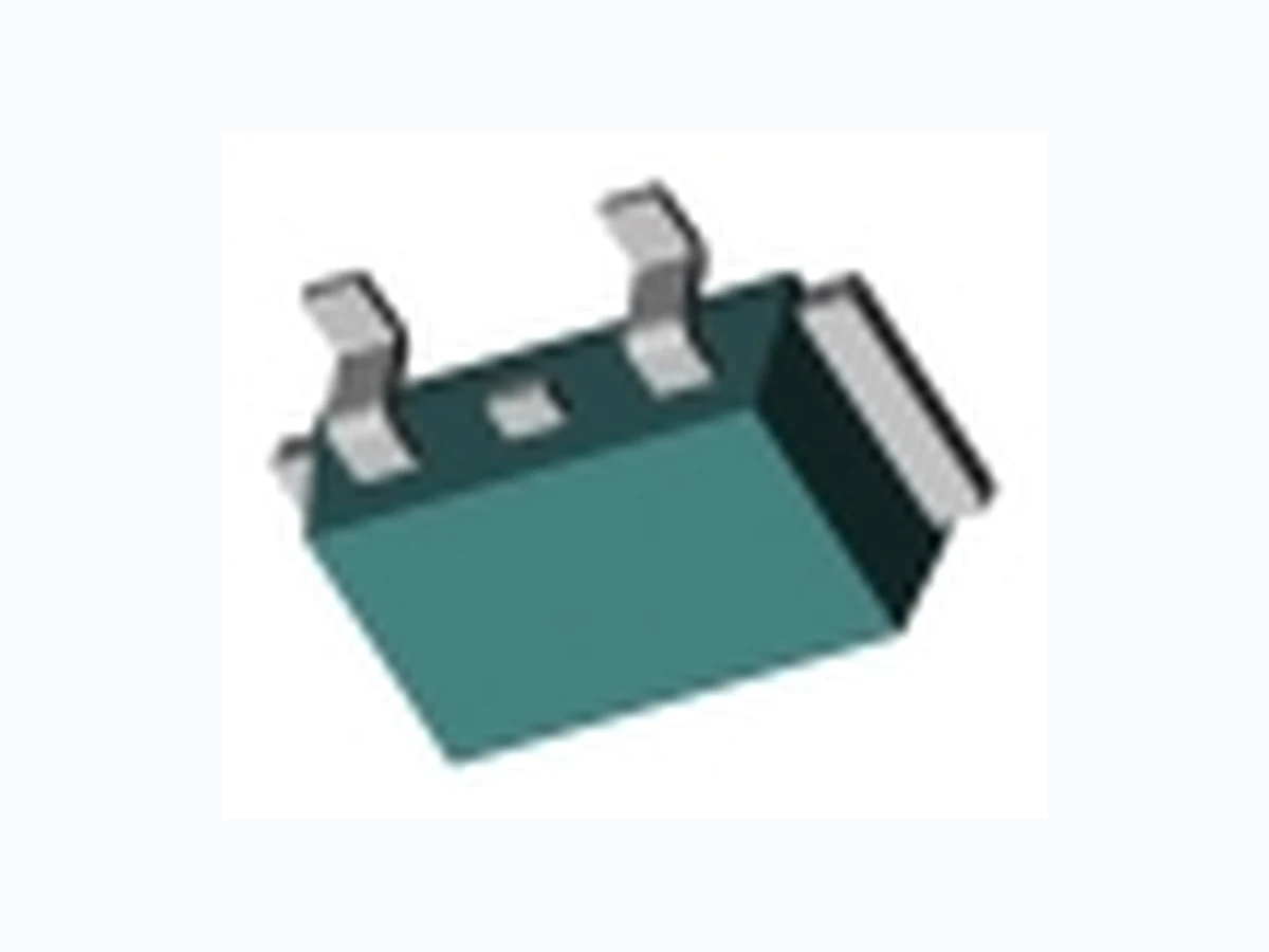
115CNQ015A IRF
Document overview
- Manufacturer or author: Provided By digicamel.com
- PDF pages: 7
Technical content
110 Amp
Bulletin PD-20632 rev. A 09/01 Major Ratings and Characteristics IF(AV) Rectangular 110 A waveform VRRM 15 V IFSM @ tp = 5 µs sine 5050 A VF @ 55 Apk, TJ = 75 °C 0.33 V (per leg) TJ range - 55 to 125 °C Characteristics 115CNQ015AUnits The 115CNQ015A center tap Schottky rectifier module has been optimized for ultra low forward voltage drop specifically for the OR-ing of parallel power supplies. The proprietary barrier technology allows for reliable operation up to 125 °C junction temperature. Typical applications are in parallel switching power supplies, converters, reverse battery protec- tion, and redundant power subsystems. 125°C T J operation (VR < 5V) Center tap module Optimized for OR-ing applications Ultra low forward voltage drop High frequency operation Guard ring for enhanced ruggedness and long term reliability High purity, high temperature epoxy encapsulation for enhanced mechanical strength and moisture resistance New fully transfer-mold low profile, small footprint, high current package Description/Features Case Styles D61-8 115CNQ015A 115CNQ015ASM 115CNQ015ASL D61-8-SM D61-8-SL www.irf.com
Bulletin PD-20632 rev. A 09/01 www.irf.com Part number 115CNQ015A VR Max. DC Reverse Voltage (V) @ T J = 100°C 15 VRWM Max. DC Reverse Voltage (V) @ T J = 125°C 5 Voltage Ratings Absolute Maximum Ratings Parameters 115CNQ Units Conditions IF(AV) Max. Average Forward Per Leg 55 A 50% duty cycle @ T C = 112 °C, rectangular wave form Current * See Fig. 5 Per Device 110 IFSM Max. Peak One Cycle Non-Repetitive 5050 5µs Sine or 3µs Rect. pulse Surge Current (Per Leg) * See Fig. 7 830 10ms Sine or 6ms Rect. pulse EAS Non-Repetitive Avalanche Energy 54 mJ T J = 25 °C, IAS = 2 Amps, L = 4.5 mH (Per Leg) IAR Repetitive Avalanche Current 2 A Current decaying linearly to zero in 1 µsec (Per Leg) Frequency limited by T J max. VA = 3 x VR typical A VFM Max. Forward Voltage Drop 0.37 V @ 55A (Per Leg) * See Fig. 1 (1) 0.46 V @ 110A
0.33 V @ 55A
0.43 V @ 110A
IRM Max. Reverse Leakage Current 20 mA T J = 25 °C (Per Leg) * See Fig. 2 (1) 1200 mA T J = 100 °C 900 mA T J = 100 °C V R = 12V 540 mA T J = 100 °C V R = 5V CT Max. Junction Capacitance (Per Leg) 5500 pF V R = 5VDC (test signal range 100Khz to 1Mhz) 25°C LS Typical Series Inductance (Per Leg) 5.5 nH Measured lead to lead 5mm from package body dv/dt Max. Voltage Rate of Change 10000 V/ µs (Rated VR) Electrical Specifications TJ = 25 °C TJ = 75 °C VR = rated VR Parameters 115CNQ Units Conditions TJ Max. Junction Temperature Range -55 to 125 °C Tstg Max. Storage Temperature Range -55 to 150 °C RthJC Max. Thermal Resistance Junction 0.5 °C/W DC operation * See Fig. 4 to Case (Per Leg) RthJC Max. Thermal Resistance Junction 0.25 °C/W DC operation to Case (Per Package) RthCS Typical Thermal Resistance, Case 0.30 °C/W Mounting surface , smooth and greased to Heatsink (D61-8 Only) Device flatness < 5 mils wt Approximate Weight 7.8 (0.28) g (oz.) T Mounting Torque Min. 40 (35) (D61-8 Only) Max. 58 (50) Thermal-Mechanical Specifications Kg-cm (Ibf-in) Parameters 115CNQ Units Conditions Following any rated load condition and with rated V RRM applied (1) Pulse Width < 300µs, Duty Cycle <2%
Bulletin PD-20632 rev. A 09/01 www.irf.com Fig. 2 - Typical Values Of Reverse Current Vs. Reverse Voltage (Per Leg) Fig. 3 - Typical Junction Capacitance Vs. Reverse Voltage (Per Leg) Fig. 4 - Max. Thermal Impedance ZthJC Characteristics (Per Leg) Fig. 1 - Max. Forward Voltage Drop Characteristics (Per Leg) Instantaneous Forward Current - I F (A) Forward Voltage Drop - VFM (V) Reverse Current - I R (mA) Reverse Voltage - VR (V) Reverse Voltage - VR (V) Junction Capacitance - C T (p F) Thermal Impedance - Z thJC (°C/W) t1 , Rectangular Pulse Duration (Seconds) 1000 10000 4 6 8 1 01 21 41 6 Tj = 25˚C 100 1000 10000 0 2 4 6 8 1 01 21 41 6 100˚C 75˚C 50˚C 25˚C Tj = 125˚C 100 1000 T = 125˚C T = 75˚C T = 25˚C J J J 0.001 0.01 0.1 Single Pulse (Thermal Resistance) D = 0.75 D = 0.50 D = 0.33 D = 0.25 D = 0.20 PDM Notes: 1. Duty factor D = t 1 / t 2 2. Peak Tj = Pdm x ZthJC + Tc
Bulletin PD-20632 rev. A 09/01 www.irf.com Fig. 5 - Max. Allowable Case Temperature Vs. Average Forward Current (Per Leg) Fig. 8 - Unclamped Inductive Test Circuit Fig. 6 - Forward Power Loss Characteristics (Per Leg) (2) Formula used: TC = TJ - (Pd + PdREV) x RthJC ; Pd = Forward Power Loss = IF(AV) x VFM @ (IF(AV) / D) (see Fig. 6); PdREV = Inverse Power Loss = VR1 x IR (1 - D); IR @ VR1 = 5V FREE-WHEEL DIODE 40HFL40S02C URRENT M ONITOR HIGH-SPEED SWITCHIRFP460 L DUT Rg = 25 ohm Vd = 25 Volt+ Allowable Case Temperature (°C) Average Forward Current - IF(AV) (A) Average Power Loss (Watts) Average Forward Current - IF(AV) (A) Non-Repetitive Surge Current - I FSM (A) Square Wave Pulse Duration - tp (microsec) Fig. 7 - Max. Non-Repetitive Surge Current (Per Leg) 100 105 110 115 120 125 0 1 02 03 04 05 06 07 08 09 0 DC see note (2) Square wave (D = 0.50) 5V applied 0 1 02 03 04 05 06 07 08 0 DC RMS Limit D = 0.75 D = 0.50 D = 0.33 D = 0.25 D = 0.20 100 1000 10000 10 100 1000 10000 At Any Rated Load Condition And With Rated Vrrm Applied Following Surge
Bulletin PD-20632 rev. A 09/01 www.irf.com Outline Table Outline D61-8-SM Dimensions are in millimeters and (inches) Outline D61-8 Dimensions are in millimeters and (inches)
Bulletin PD-20632 rev. A 09/01 www.irf.com Outline Table Outline D61-8-SL Dimensions are in millimeters and (inches) Marking Information THIS IS A 115CNQ015A WITH LOT CODE 89 09 ASSEMBLED ON WW 45, 2000 IN THE ASSEMBLY LINE "A" ASSEMBLY LOT CODE INTERNATIONAL RECTIFIER LOGO PART NUMBER DATE CODE YEAR 0 = 2000 WEEK 45 LINE A 115CNQ015A 89 09 045A
Bulletin PD-20632 rev. A 09/01 www.irf.com IR WORLD HEADQUARTERS: 233 Kansas St., El Segundo, California 90245, USA Tel: (310) 252-7105 TAC Fax: (310) 252-7309 Visit us at www.irf.com for sales contact information. 09/01 Data and specifications subject to change without notice. This product has been designed and qualified for Industrial Level. Qualification Standards can be found on IR's Web site.