

 Download PDF
110 CTS
Document overview
- PDF pages: 3
Technical content
Page 1

®
Commercial
3/4" (19mm)
Diameter, 11/2and 2
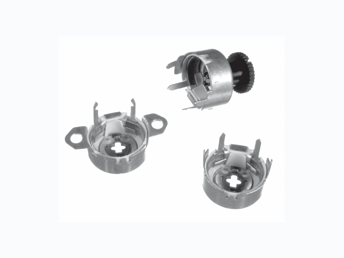
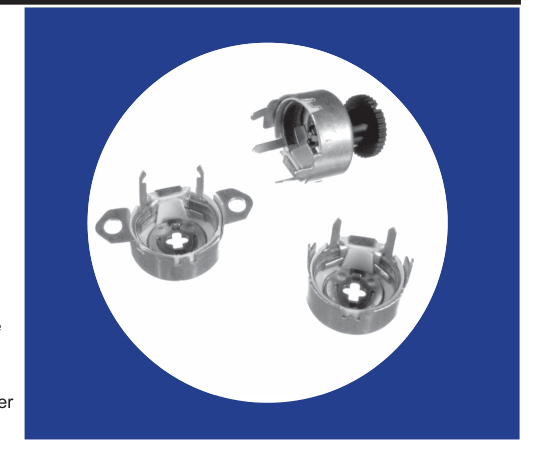
Watt Wirewound
Variable Resistors
Features
- Inexpensive design
- Open construction
- Four mounting styles
- Incorporated fixed resistor available
- Available with nylon knob
- Interchangeable mounting with
CTS Series 115 preset potentiometer
- RoHS compliant
Electrical and Mechanical Specifications
Resistance Range 1 ohm through 10K ohms (linear taper)
Resistance Tolerance Standard:±20% Special:±5% or 10%
Power Rating, Watts 2 watts @ 55°C derated to no load @ 105°C, mounted on steel panel 1.5 watts @ 55°C derated to no load @ 105°C, mounted on bakelite panel
Voltage Rating Determined by resistance value and wattage rating
Resistance Taper Standard:Linear taper only
Minimum Resistance At ends of rotation: 1% or 1 ohm, whichever is greater
Resistance Taper None
Incorporated Fixed Resistor A fixed resistor can be incorporated in the Series 110 at the end of CW or CCW rotation to a minimum of 10% of the total resistance. The rotation is shortened by an amount proportional to the ratio of the fixed resistor to the total resistance. Available at extra cost.
Angle of Rotation 246°±5°without fixed resistor stop
Resistor Adjustment Standard Cross Slot: Provided in drive plate for screwdriver adjustment. Special Molded Knob: Available at extra cost secured to drive plate cross slot.
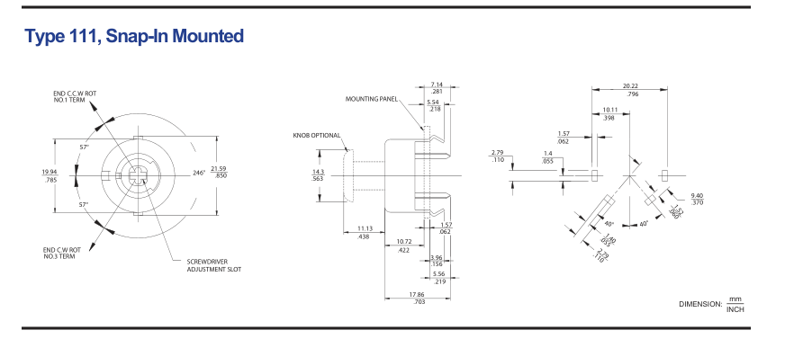
Mounting Types Available Type 110:
Solder or clinch-ear mounted
Type XPC - 110: Vertically mounted on printed circuit board Type 111:
Snap-in mounting
Type 112:
Eyelet or rivet mounting
Rotational Torque 1/2 to 10 inch ounces (36 – 720 gf-cm)
Terminals Terminals at end of CW or CCW rotation may be omitted. Refer to terminals on all types by numbers 1 and 3 as indicated on line drawings.
© 2006 CTS Corporati on. All ri ghts reserved. Informati on subject to change.
1 - 3
9/30/06
CTS Electronic Components
www.ctscorp.com
Page 2
Type 110, Solder or Clinch-Ear Mounted, Long Terminal Length
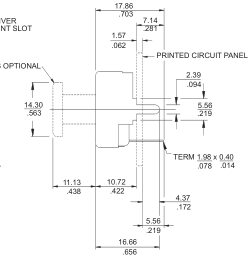
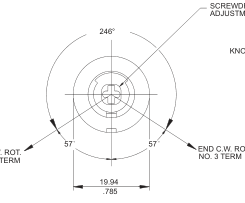
SCREWDRIVER ADJUSTMENT SLOT
END C.C.W. ROT. NO. 1 TERM
U - Long Terminal Length
mm DIMENSION: INCH
TYPE M110, Solder Mounted, Medium Terminal Length
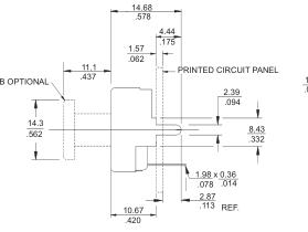
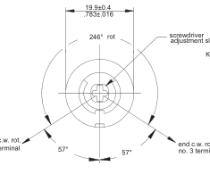
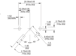
end c.w. rot. no. 1 terminal
M - Medium Terminal Length
mm DIMENSION: INCH
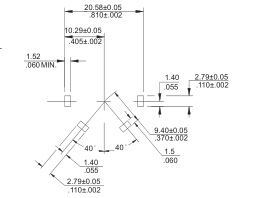
TYPE XPC110, Vertically Mounted
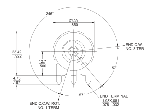
11.91 .469
2.77 DIA. .109
5.77 .227
28.17
7.62
1.109
.300 15.24 .600
CENTER TERMINAL 1.98X0.41 .078 .016
mm DIMENSION: INCH
Page 3
Type 112, Eyelet or Rivet Mounted
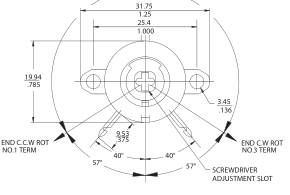
240° ROT.
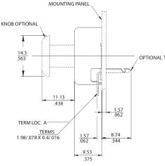
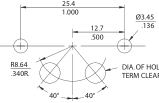
OPTIONAL TERM LOC. B
DIA. OF HOLE TO SUIT TERM CLEARANCE.
mm DIMENSION: INCH
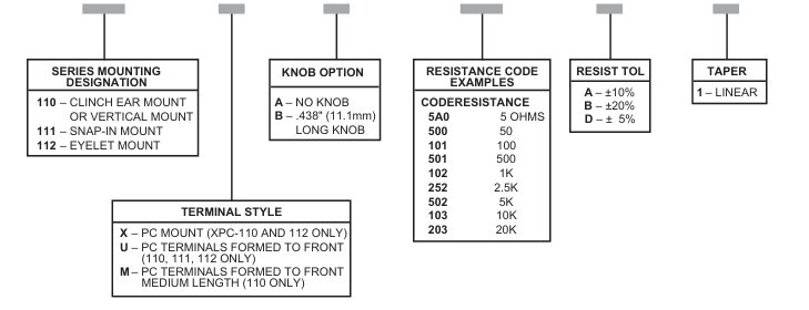
Ordering Information
A
103
B
1
110
U
© 2006 CTS Corporati on. All ri ghts reserved. Informati on subject to change.
3 - 3
9/30/06