
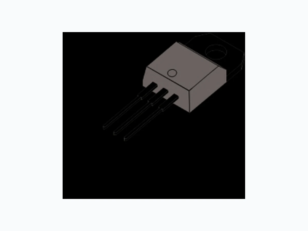
10PT NELLSEMI
Document overview
- Manufacturer or author: Provided By www.digicamel.com(FREE DATASHEET DOWNLOAD SITE)
- PDF pages: 5
Technical content
SEMICONDUCTOR 10PT Series RoHS RoHS Stansard SCRs, 10A SYMBOL IT(RMS) RMS on-state current full sine wave ITSM Non repetitive surge peak on-state current (full cycle, T initial = 25°C)j A I t22I t Value for fusing 50 2A s dI/dtCritical rate of rise of on-state current 50 IGMPeak gate current PG(AV)Average gate power dissipation TstgStorage temperature range Operating junction temperature range - 40 to + 150 - 40 to + 125 ºC A/µs A A W UNITVALUE 100 105 F =50 Hz F =60 Hz t = 20 ms t = 16.7 ms t = 10 msp F = 60 Hz T =125ºCj T = 125ºCj T = 125ºCj T = 20 µsp Tj ABSOLUTE MAXIMUM RATINGS PARAMETER TEST CONDITIONS Main Features Symbol Value Unit IT(RMS) V /VDRM RRM IGT 10 A V mA15 600 to 1000
DESCRIPTION
V600 to 1000 T =125ºCj VDRM VRRM Repetitive peak off-state voltage Repetitive peak reverse voltage (180° conduction angle ) Average on-state current (180° conduction angle) IT(AV) A K A G K A G A A A K A G TO-220AB (Non-lnsulated) TO-251 (I-PAK) TO-252 (D-PAK) I = 2xl , t ≤100nsG GT r KA G TO-220AB (lnsulated) (10PTxxF) (10PTxxG) (10PTxxA) (10PTxxAI) www.nellsemi.com TO-251/TO-252/TO-220AB TO-220AB insulated T =100°CC T =90°CC Maximum gate power PGM W10T =20µsp The 10PT series of silicon controlled rectifiers are high performance glass passivated technology, and are designed for power supply up to 400Hz on resistive or inductive load. T = 125ºCj TO-220AB insulated T =100°CC T =90°CC 6.4 TO-251/TO-252/TO-220AB 3(G) 1(K) 2(A)
Note: xx = voltage 10PTxxxx Unit IGT VGD IH mA dV/dt VTM IDRM IRRM mA IL V = 12V, R = 30ΩD L V = V , R = 3.3KD DRM L Ω R = 220Ω, T = 110°CGK j I = 100mA, Gate openT I = 1.2 × IG GT V = 67% V Gate open, T = 110°CD DRM j, 1.3 0.2 200 mA V V mA V/µs I = 20A, T t = 380 µsP T = 110°Cj T = 25°Cj T = 25°Cj V µA ELECTRICAL SPECIFICATIONS (TJ = 25 unless otherwise specified)ºC, TEST CONDITIONS SYMBOL V =V , V =VD DRM R RRM 1.6 2R = 220ΩGK Max. Max. Min. Max. Max. Min. Max. Max. Max. THERMAL RESISTANCE Rth(j-c) Junction to case (DC) Rth(j-a) Junction to ambient 2.5 °C/W °C/W UNITVALUESYMBOL Parameter VGT µS70tq T = 110°Cj TYP.V = 67% V I , V = 25VD DRM R, = 12ATM dI = 30A/µs, dV /dt = 50V/µsTM D PRODUCT SELECTOR PART NUMBER VOLTAGE (xx) SENSITIVITY 600 V 15 mA 1000 V 10PTxxA/10PTxxAl 10PTxxF 10PTxxG VV 800 V V PACKAGE TO-220AB D-PAK VV V V V V I-PAK 15 mA 15 mA
ORDERING INFORMATION
ORDERING TYPE MARKING PACKAGE WEIGHT ,BASE Q TY DELIVERY MODE TO-220AB 2.0g 50 Tube 10PTxxAI 10PTxxAI 2.3g 50 Tube 10PTxxF 10PTxxF TO-251(I-PAK) 0.40g 80 10PTxxG 10PTxxG 0.38g 80 TubeTO-252(D-PAK) TO-220AB (insulated) Tube 100 IPAK/DPAK/TO-220AB S=0.5 cm² DPAK IPAK TO-220AB S=Copper surface under tab Page 2 of 5www.nellsemi.com SEMICONDUCTOR 10PT Series RoHS RoHS
ORDERING INFORMATION SCHEME SCR series Package type Current Voltage Code A = TO-220AB (non-insulated) AI = TO-220AB ( insulated) 10 = 10A, IT(RMS)
10 PT 06
06 = 600V F = TO-251 (IPAK) G = TO-252 (DPAK) 08 = 800V 10 = 1000V Fig.1 Maximum average power dissdipation versus average on-state current Fig.2 Correlation between maximum average power dissipation and maximum allowable temperature(T and T )amb lead 876543210 9 0 20 40 60 80 100 120 140 P(W) P(W) T (°C)lead DC α=90° α=60° α=120° α=30° α=180° Tamb(°C) α=180° R =6°C/Wth R =4°C/Wth R =2°C/Wth R =0°C/Wth 125 120 115 110 105 100 I (A)T(AV) 360° α Page 3 of 5www.nellsemi.com SEMICONDUCTOR 10PT Series RoHS RoHS
I ,I ,I [T ] / I ,I ,I [T =25°C]GT H L j GT H L j Fig.5 Relative variation of gate trigger current junction temperatureversus Fig.8 On-state characteristics (maximum values) 100 1 2 5 10 Fig.6 Surge peak on-state current versus number of cycles 2.5 1 10 100 1000 I (A)TSM 1002 1.5 0.5 0 10 20 30 40 50 60 70 80 90 100 110-20-30 -10-40 I (A),I²t(A²s)TSM Fig.7 Non-repetitive surge peak on-state current for a sinusoidal pulse with width tp < 10 ms, and corresponding values of l²t I (A)TM 1 2 43 5 100 1000 Fig.3 Average on-state current versus case temperature Fig.4 Relative variation of thermal impedance versus pulse duration 0 10 20 30 40 50 60 70 80 90 100 110 120 130 0.1 0.01 1E-3 1E-2 1E-1 1E+0 1E+1 1E+2 5E+2 I (AV)(A)T K=[Z /R ]th(j-c) th(j-c) T (°C)case α=180° DC
10 TO-220AB
t (s)p Zth(j-c) Zth(j-a) T (°C)j IGT I &IH L Number of cycles Tj inital=25°C tp=10ms One cycle 120 t (ms)p I²t ITSM Tj inital=25°C VTM(V) Tj=max Vt0=0.82V Rd=24mΩ Tj=max Tj=25°C Page 4 of 5www.nellsemi.com SEMICONDUCTOR 10PT Series RoHS RoHS
1.14(0.045) 0.89(0.035) 0.76(0.030) 2.28(0.090) 4.57(0.180) 0.64(0.025) 6.4(0.251) 6.6(0.259) 5.4(0.212) 5.2(0.204) 1.5(0.059) 1.37(0.054) 9.35(0.368) 10.1(0.397) 2.4(0.095) 2.2(0.086) 0.62(0.024) 0.48(0.019) 6.2(0.244) 6(0.236) 0.62(0.024) 0.45(0.017) TO-252 (D-PAK) Case Style 6.4(0.52) 6.6(0.26) 5.2(0.204) 1.37(0.054) 9.4(0.37) 9(0.354) 16.3(0.641) 15.9(0.626) 4.6(0.181) 4.4(0.173) 0.85(0.033) 0.55(0.021) 1.9(0.075) 1.8(0.071) 2.4(0.095) 2.2(0.086) 0.62(0.024) 0.48(0.019) 0.62(0.024) 0.45(0.017) 6.2(0.244) 6(0.236) TO-251 (I-PAK) 2.87 (0.113) 2.62 (0.103) 9.40 (0.370) 9.14 (0.360) 10.54 (0.415) MAX. 16.13 (0.635) 15.87 (0.625) PIN 4.06 (0.160) 3.56 (0.140) 1.45 (0.057) 1.14 (0.045) 2.67 (0.105) 2.41 (0.095) 2.65 (0.104) 2.45 (0.096) 5.20 (0.205) 4.95 (0.195) 0.90 (0.035) 0.70 (0.028) 3.91 (0.154) 3.74 (0.148) K G A 4.70 (0.185) 4.44 0.1754 ( ) 1.39 (0.055) 1.14 (0.045) 3.68 (0.145) 3.43 (0.135) 8.89 (0.350) 8.38 (0.330) 29.16 (1.148) 28.40 (1.118) 14.22 (0.560) 13.46 (0.530) 0.56 (0.022) 0.36 (0.014) 2.79 (0.110) 2.54 (0.100) 15.32 (0.603) 14.55 (0.573) TO-220AB Page 5 of 5www.nellsemi.com SEMICONDUCTOR 10PT Series RoHS RoHS 3(G) 1(K) 2(A) K G A A K G A A