
DATASHEET SEARCH SITE
Document overview
- Manufacturer or author: Provided By digicamel.com
- PDF pages: 10
Technical content
Features
– 1 counter input for 24 V or 5 V signals – 1 control input for 24 V or 5 V signals – 1 freely parameterizable switching output – Diagnostic and status indicators – Can be used under extreme ambient conditions – Extended temperature range of -40°C ... +70°C (see “Tested successfully: use under extreme ambient conditions”) –P a i n t e d P C B s This data sheet is only valid in association with the IL SYS INST UM E user manual. For additional information, please refer to the user manual for the counter terminal. Make sure you always use the latest documentation. It can be downloaded from the product at phoenixcontact.net/products. 106148_en_03 2015-11-04
106148_en_03 PHOENIX CONTACT 2 2T a b l e o f c o n t e n t s
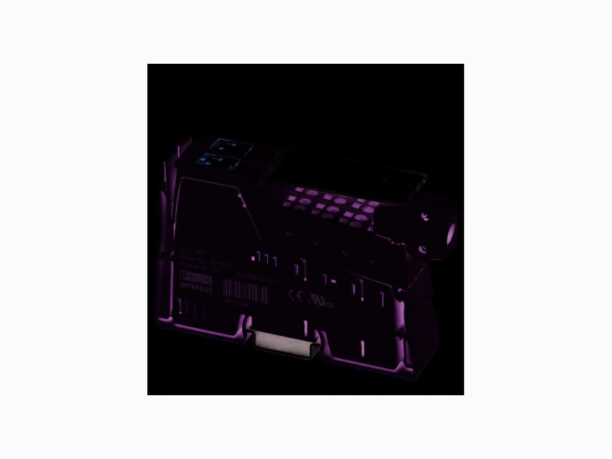
106148_en_03 PHOENIX CONTACT 3 Description Type Order No. Pcs./Pkt. Inline counter terminal, version for extreme conditions, complete with ac- cessories (connectors and marking fields), 1 counter input, 1 control input, 1 output, 24 V DC, 500 mA, 3-conductor connection technology IB IL CNT-XC-PAC 2702134 1 3O r d e r i n g d a t a Accessories Type Order No. Pcs./Pkt. Connector set (Connector/Adapter) IB IL AO/CNT-PLSET 2732664 1 Labeling field, width: 12.2 mm (Marking) IB IL FIELD 2 2727501 10 Insert strip, Sheet, white, unlabeled, can be labeled with: Office printing systems, Plotter: Laser printer, Mounting type: Insert, Lettering field: 62 x 10 mm (Marking) ESL 62X10 0809492 1 Connector, for digital 1, 2 or 8-channel Inline terminals (Connector/ Adapter) IB IL SCN-8 2726337 10 Inline shield connector (Connector/Adapter) IB IL SCN-6 SHIELD 2726353 5 Documentation Type Order No. Pcs./Pkt. User manual, English, Inline Modular counter terminal IB IL CNT UM E - - User manual, English, Automation terminals of the Inline product range IL SYS INST UM E - - Data sheet, English, INTERBUS addressing DB GB IBS SYS ADDRESS - - Dimensions (nominal sizes in mm) Width 24.4 mm Height 135 mm Depth 71.5 mm Note on dimensions Housing dimensions
4 Technical data
119,8 71,5 General data Color green Weight 130 g (with connectors) Operating mode Process data operation with 2 words Ambient temperature (operation) -25 °C ... 55 °C (Standard) -40 °C ... 70 °C (Extended, see section “Tested successfully: use under extreme ambient conditions” in the data sheet.) Ambient temperature (storage/transport) -40 °C ... 85 °C Permissible humidity (operation) 10 % ... 95 % (according to DIN EN 61131-2) Permissible humidity (storage/transport) 10 % ... 95 % (according to DIN EN 61131-2)
106148_en_03 PHOENIX CONTACT 4 Air pressure (operation) 70 kPa ... 106 kPa (up to 3000 m above sea level) Air pressure (storage/transport) 70 kPa ... 106 kPa (up to 3000 m above sea level) Degree of protection IP20 Protection class III, IEC 61140, EN 61140, VDE 0140-1 General data Connection data Designation Inline connector Connection method Spring-cage connection Conductor cross section [AWG] 28 ... 16 Stripping length 8 mm Connection data for UL approvals Designation Inline connector Connection method Spring-cage connection Conductor cross section [AWG] 24 ... 16 Interface Inline local bus Connection method Inline data jumper Transmission speed 500 kBit/s Transmission physics Copper Supply: Power supply for sensors Supply voltage 24 V DC (generated from segment supply U S) Current carrying capacity max. 500 mA Behavior in case of short-circuit Auto restart after eliminating the short-circuit Power consumption Segment supply voltage US 24 V DC (nominal value) Current consumption from US max. 1 A Communications power UL 7.5 V DC (via voltage jumper) Current consumption from UL typ. 40 mA max. 50 mA Power consumption max. 0.375 W (at U L) Counter input for 24 V signals Number of inputs 1 (only one counter input can be used, either for 24 V or for 5 V signals) Operating mode Event counting, frequency/time measurement Connection method Spring-cage connection Connection method 2, 3-wire Input voltage 24 V DC (Nominal voltage) Nominal input current typ. 5 mA Input voltage range "0" signal 0 V DC ... 5 V DC Input voltage range "1" signal 15 V DC ... 30 V DC Input resistance approx. 5.7 k Ω Counter input for 5 V signals Number of inputs 1 (only one counter input can be used, either for 24 V or for 5 V signals) Operating mode Event counting, frequency/time measurement Connection method Spring-cage connection
106148_en_03 PHOENIX CONTACT 5 Connection method 2-wire (shielded), external 5 V supply Input voltage 5 V DC (Nominal voltage) Nominal input current typ. 5 mA Input voltage range "0" signal 0 V ... 1.5 V Input voltage range "1" signal 3.5 V ... 8 V Input resistance approx. 1.7 k Ω Counter input for 5 V signals Control input for 24 V signals Number of inputs 1 (only one control input can be used, either for 24 V or for 5 V signals) Operating mode Event counting, frequency/time measurement Connection method Spring-cage connection Connection method 2, 3-wire Input voltage 24 V DC (Nominal voltage) Nominal input current typ. 5 mA Input voltage range "0" signal 0 V ... 5 V Input voltage range "1" signal 15 V ... 30 V Input resistance approx. 5.7 k Ω Control input for 5 V signals Number of inputs 1 (only one control input can be used, either for 24 V or for 5 V signals) Operating mode Event counting, frequency/time measurement Connection method Spring-cage connection Connection method 2-wire (shielded), external 5 V supply Input voltage 5 V DC (Nominal voltage) Nominal input current typ. 5 mA Input voltage range "0" signal 0 V ... 1.5 V Input voltage range "1" signal 3.5 V ... 8 V Input resistance approx. 1.7 k Ω Switching output Number of outputs 1 Connection method Spring-cage connection Connection method 2-wire Output voltage 24 V DC (Nominal voltage) Output current max. 0.5 A (Nominal current) Voltage difference with nominal current < 1 V Nominal load, ohmic max. 12 W (48 Ω) Nominal load, inductive max. 12 VA (1.2 H; 48 Ω) Nominal load, lamp max. 12 W Signal delay when switching on an ohmic nominal load < 50 µs Signal delay when switching on an inductive nominal load < 1 ms Signal delay when switching on a lamp nominal load < 25 µs Signal delay when switching off an ohmic nominal load < 1 ms Signal delay when switching off an inductive nominal load < 30 ms Signal delay when switching off a lamp nominal load < 1 ms Limitation of the voltage induced on circuit interruption approx. -18 V Behavior in the event of ohmic overload Au to restart after eliminating the overload Behavior with inductive overload Output can be destroyed Behavior in the event of lamp overload Au to restart after eliminating the overload
106148_en_03 PHOENIX CONTACT 6 The characteristics of a bulb can delay the auto restart significantly after eliminating the overload. The delay time can be reduced by briefly setting the output. Reverse voltage resistance to short pulses Reverse voltage proof Resistance to permanently applied surge voltage No Overcurrent shut-down min. 0.7 A Short-circuit protection Yes, short-circuit-proof (automatically switched on again) Overload protection Yes Switching output Programming data (INTERBUS, local bus) ID code (hex) BF ID code (dec.) 191 Length code (hex) 02 Length code (dec.) 02 Process data channel 32 Bit Input address area 4 Byte Output address area 4 Byte Parameter channel (PCP) 0 Byte Register length (bus) 4 Byte For the programming data/configuration data of other bus systems, please refer to the corresponding electronic device data sheet (e.g., GSD, EDS). NOTE: Misinterpretation of values when the data consistency is violated Ensure data consistency of two words to prevent the possibility of the values being misinterpreted. Configuration and parameter data in a PROFIBUS system Required parameter data 1 Byte Need for configuration data 5 Byte Error messages to the higher level control or computer system Sensor supply short-circuit Sensor supply overload If the sensor supply is short-circuited, the red E LED (Error) lights up and an I/O error message is generated after a delay of typically 1.4 s. In addition, the D LED (Diagnostics) flashes on the terminal at 2 Hz (medium). Electrical isolation/isolation of the voltage areas Test section Test voltage 5 V supply, incoming remote bus/7.5 V supply (bus logics) 500 V AC, 50 Hz, 1 min 5 V supply, outgoing remote bus/7.5 V supply (bus logics) 500 V AC, 50 Hz, 1 min
7.5 V supply (bus logics)/24 V supply (I/O) 500 V AC, 50 Hz, 1 min
24 V supply (I/O) / functional earth ground 500 V AC, 50 Hz, 1 min
To achieve electrical isolation between the logic level and the I/O area, supply these areas from separate power supply units. Interconnection of the power supply units in the 24 V area is not permitted (see also user manual). Approvals For the latest approvals, please visit phoenixcontact.net/products.
106148_en_03 PHOENIX CONTACT 7
5 Additional tables
Input characteristic curve Input voltage (V) Typical input current (mA) -0.5 < UIN < 0 0 3 0.6 61 . 1 9 1.7 12 2.3 15 2.4 18 3.6 21 4.3 24 5.0 27 5.5 30 6.1 Switching output Output characteristic curve when switched on (typi- cal) Output current (A) Differential output volt- age (V) 0.1 0.25 0.2 0.35 0.3 0.45 0.4 0.55 0.5 0.65 Sensor supply Output characteristic curve when switched on (typi- cal) Output current (A) Differential output volt- age (V) 0.1 0.18 0.2 0.22 0.3 0.27 0.4 0.31 0.5 0.36 Limit values and limitations in the operating modes Operating mode Affected option Operating range Frequency mea- surement All f ≤ 100 kHz Event counting All f ≤ 100 kHz Time measure- ment Resolution 2 µs Without relation condition 250 µs ≤ t ≤ 126 ms With relation condition 1 ms ≤ t ≤ 126 ms Resolution 2 ms 2 ms ≤ t ≤ 131 s Resolution 10 ms 10 ms ≤ t ≤ 655 s Pulse generator 1 kHz ≤ f ≤ 10 kHz Notes on using the counter terminal Minimum time mea- surement period The minimum time measurement periods with a res- olution of 2 µs, with and without relation condition, are defined by the firmware by means of the pro- cessing time. Input signals at source and gate The input signals at source and gate must be digital. Switch The counter terminal is primarily designed for the use of electronic switching elements, i.e., semicon- ductor switches. Mechanical contacts can only be used to a limited extent. A filter is provided in the input circuit for this purpose. However, practical tests have shown that the bouncing of mechanical contacts can present problems even with this filter.
106148_en_03 PHOENIX CONTACT 8
6 Tested successfully: Use under ex-
XC terminals have been tested successfully over 250 tem- perature change cycles in accordance with IEC 61131-2 in the range from -40°C to +70°C. The following conditions were observed: – The Inline devices for all connecting cables were con- nected with a minimum conductor cross section of 0.5 mm² – The Inline station was a ssembled on a wall-mounted horizontal DIN rail – Fans were used to ensure continuous movement of air in the control cabinet – The Inline station was not exposed to vibration or shock – The Inline station was oper ated with a maximum of
24.5 V (ensured by using regulated power supply units)
Figure 1 Temperature change cycle
7 Internal circuit diagram
Figure 2 Internal wiring of the terminal points Key: Temperature in the control cabinet/ambient temperature Cycle WARNING: The terminal is not approved for use in poten- tially explosive areas. The terminal is not approved for use in safety technology. 3 h + 30 min 3 h + 30 min (3 0,6) K/min+
3 K+Tmin
2 K+Tmax
(Bus logic including voltage conditioning) Microprocessor Optocoupler Digital input Digital output Transistor Coupling network Module with multiplexer, filter, and logic Sensor supply with short-circuit protection Explanation for other used symbols has been provided in the IL SYS INST UM E user man- ual. +24 V (U )M +24 V (U )S Local bus UL+ UANA UL- UINI OPC µP MUX /UNIf0b3 ## # OPC µP MUX
106148_en_03 PHOENIX CONTACT 9
8 Terminal point assignment
Figure 3 Terminal point assignment
9 Connection example
Figure 4 Connection example Terminal point Signal Assignment Connector 1
1.1 S+ 24 V counter input (source)
2.1 G+ 24 V control input (gate)
1.2, 2.2 U INI 24 V DC sensor voltage
1.3 S- Reference ground for the counter
input (source) and the sensor volt- age
2.3 G- Reference ground for the control
input (gate) and the sensor voltage 1.4, 2.4 Shield Shield (cap acitively coupled to FE) Connector 2
1.1 S+* 5 V counter input (source)
2.1 G+* Control input 5 V (gate)
1.2, 2.2 OUT Output; the terminal points are jumpered internally. 1.3, 2.3 GND Reference gr ound for the output; the terminal points are jumpered internally. 1.4, 2.4 FE Functional earth ground (con- nected directly to FE) The short-circuit-protected sensor voltage U INI is generated from the segment voltage US. The main voltage UM is not used at the counter terminal points. 1.1 2.1 1.2 2.2 1.3 2.3 1.4 2.4 1.1 2.1 1.2 2.2 1.3 2.3 1.4 2.4 1.1 1.2 1.3 1.1 1.2 1.3 1.4 2.1 2.2 2.3 2.1 2.2 2.3 2.4 When connecting the sensors observe the as- signment of the terminal points to the process data. This can be found in the user manual for the counter terminal. 1.2 2.2 1.3 2.3 1.4 2.4 1.1 2.1 1.2 2.2 1.3 2.3 1.4 2.4 1.1 2.1 OUT 1 +24 V IN 2 +24 V IN 1
106148_en_03 10PHOENIX CONTACT GmbH & Co. KG • 32823 Blomberg • Germany phoenixcontact.com
10 Local status and diagnostic indica-
Figure 5 Local status and diagnostic indicators Function identification Orange
11 Function description
–E v e n t c o u n t i n g : The counting conditions and the output switching be- havior can be selected. – Frequency measurement: Time-driven or state-driven frequency measurements with gate times (time in which measurement is per- formed) from 10 ms to 10 s are possible. – Time measurement: Relation conditions can be evaluated during time mea- surement. The result of the evaluation can be output via the process data or the digital output. This allows a con- trolled response when values exceed or fall below the limit values. –P u l s e g e n e r a t o r : The pulse generator generates square-wave signals with frequencies of 1 kHz to 10 kHz in 500 Hz incre- ments. – The event counting and frequency measurement modes yield a 24-bit measured value. – The time measurement mode yields a 16-bit measured value. – A combination of source and gate signal can be select- ed as a counter signal. – During operation, a start value or final value can be changed without the counter having to be stopped. – An RC filter can be connected to source and gate. This allows the use of mechanical switches. – It is not necessary to send a counter start command to start the counting process. Counting starts immediately after the command for selecting the operating mode is transmitted. Designa- tion Color Meaning D Green Diagnostics (bus and logic volt- age) ON Local bus active. Flashing
0.5 Hz:
(slow) Communications power not pres- ent, bus system is not active
2 Hz: (me-
dium) Communications power present, bus active, I/O error.
4 Hz:
(fast) Communications power present, bus connection to the flashing ter- minal has failed; terminals behind the flashing terminal are not part of the configuration frame OFF Communications power not pres- ent, bus system is not active E Red Sensor supply short-circuit ON Connector 1 short-circuited be- tween terminals 1.2 and 1.3 or be- tween terminals 2.2 and 2.3 OFF No error S Yellow Status of the counter input (source) ON Input is active. OFF Input is inactive. G Yellow Status of the control input (gate) ON Input is active. OFF Input is inactive.
1 Yellow Output status
ON Output is set. OFF Output is not set. DS G E An overview of the function of the terminal is provided here. For a more detailed descrip- tion, please refer to the user manual for the counter terminal. For additional information on the terminal, such as a description of the process data and commands, as well as examples, please refer to the UM EN IB IL CNT-PAC user manual.