
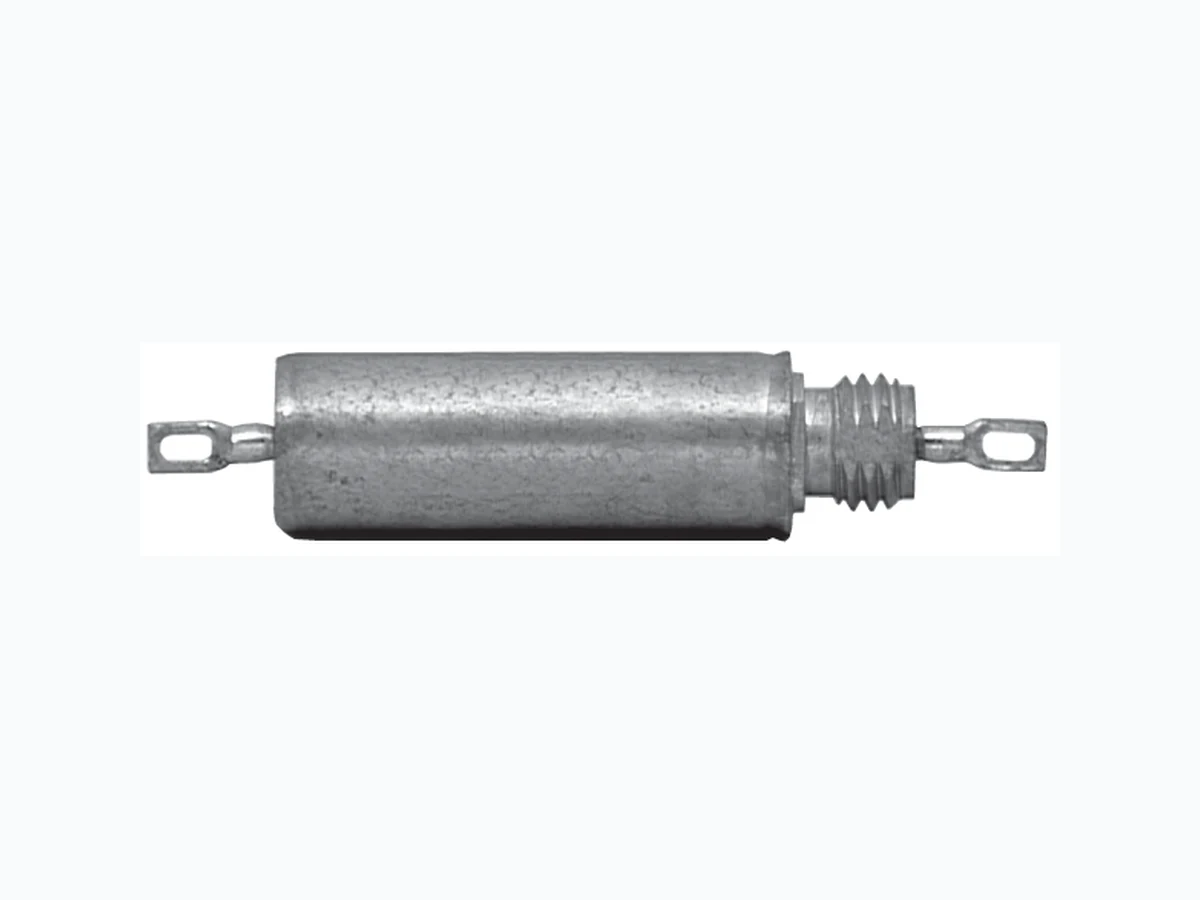
103P VISHAY
Document overview
- Manufacturer or author: Provided By www.digicamel.com(free datasheet download site)
- PDF pages: 2
Technical content
Document Number: 42032 Revision 17-Nov-03 www.vishay.com Type 103P Vishay Sprague For technical questions, contact spresale@vishay.com Paper Capacitors Metal Case, Film/Foil, 10 Ampere Thru-Pass, Subminiature
FEATURES
- Bulkhead mounting
- Excellent RFI specifications
- Hermetically encased
- Low inductance connection
- Low insertion loss PERFORMANCE CHARACTERISTICS Operating Temperature: - 55°C to + 125°C. Capacitance Range: 0.001µF to 1.0µF. Capacitance Tolerance: ± 20%, ± 10%. Voltage Rating: 200 WVDC to 600 WVDC. Current Rating: 10 ampere maximum. Dissipation Factor: 1.0% maximum. DC Resistance: 0.01 ohm maximum. Voltage Test: 200% of rated voltage for 1 minute. Insulation Resistance: At + 25°C: 20,000 Megohm - Microfarads or 30,000 Megohm minimum. At + 85°C: 200 Megohm - Microfarads or 300 Megohm minimum. DC Life Test: 140% of rated voltage for 250 hours @ + 125°C. No open or short circuits. No visible damage. Maximum ∆ Cap.: ± 5%. Minimum I.R. = 30% of initial Moisture Resistance: MIL-STD-202, Method 106E, 10 cycles. No visible damage. Maximum ∆ Cap.: ± 5%. Thermal Shock and Immersion Cycling: No visible ENVIRONMENTAL CHARACTERISTICS Vibration Test (Condition A): No mechanical damage, short, open or intermittent circuits. PHYSICAL CHARACTERISTICS Lead Pull: 5 pounds (2.3 kilograms) for one minute. No physical damage. Lead Bend: After three complete consecutive bends, no damage. Marking: Sprague® trademark, type or part number, capacitance and voltage. DIMENSIONS in inches [millimeters] Circuit Diagram 0.125 ± 0.015 [3.18 ± 0.38] L ± 0.031 [0.79] External Toothed Lockwasher Pt. No. 2-123 0.040 + 0.004 - 0.001 Dia. No. 18 AWG Solid Tinned Leads 0.125 [3.18] Max. 0.437 ± 0.015 [11.10 ± 0.38] Across Flats D + 0.015 [0.38] - 0.005 [0.130] Dia. Nut 5/16 [7.938]
24 UNF-2A
Pt. No. 6-113 Straddle Milled Flats on Thread for Locking on Mounting Surface 0.255 [6.48] 0.250 [6.35] Across Flats 0.312 ± 0.031 [7.92 ± 0.79]
www.vishay.com Type 103P Vishay Sprague Document Number: 42032 Revision 17-Nov-03 For technical questions, contact spresale@vishay.com Tab Terminals 0.020 ± 0.005 [0.51 ± 0.13] 0.296 ± 0.062 [7.52 ± 1.57] 0.156 ± 0.015 [3.96 ± 0.38] .312 ± 0.031 [7.92 ± 0.79] C L C L 0.255 [6.48] 0.250 [6.35] Across Flats Slot 0.060 [1.52] 0.050 [1.27] x 0.125 [3.18] C L C L 0.187 ± 0.015 [4.75 ± 0.38] STANDARD RATINGS in inches [millimeters] PART NUMBER* TAB TERMINAL WIRE LEAD
200 WVDC
103P104X0200T 103P224X0200T 103P474X0200T 103P105X0200T NOMINAL CASE SIZE D x L 0.400 x 0.875 [10.16 x 22.23] 0.400 x 1.125 [10.16 x 28.58] 0.562 x 1.125 [14.27 x 28.58] 0.562 x 1.875 [14.27 x 47.63] 0.750 x 2.125 [19.05 x 53.98] 0.047 0.10 0.22 0.47 1.00 CAPACITANCE (µF)
300 WVDC
0.047 0.10 0.22 0.47
400 WVDC
0.047 0.10 0.22 0.47
600 WVDC
0.001 0.0047 0.01 0.047 0.10 0.22 0.47 The Part Numbers given are for capacitance tolerance of ± 20%. To specify ± 10% tolerance, change X0 to X9. All standard inventoried Part Numbers will be stocked with a ± 10% tolerance (X9). 103P473X0300T 103P104X0300T 103P224X0300T 103P474X0300T 103P473X0400T 103P104X0400T 103P224X0400T** 103P474X0400T 103P473X0300S 103P104X0300S 103P224X0300S 103P474X0300S 103P473X0400S 103P104X0400S* 103P224X0400S* 103P474X0400S 0.400 x 1.125 [10.16 x 28.58] 0.400 x 1.375 [10.16 x 34.93] 0.562 x 1.375 [14.27 x 34.93] 0.670 x 1.875 [17.02 x 47.63] 0.400 x 1.375 [10.16 x 34.93] 0.562 x 1.125 [14.27 x 28.58] 0.562 x 1.875 [14.27 x 47.63] 0.750 x 2.125 [19.05 x 53.98] 0.400 x 0.750 [10.16 x 19.05] 0.400 x 0.750 [10.16 x 19.05] 0.400 x 0.750 [10.16 x 19.05] 0.400 x 1.375 [10.16 x 34.93] 0.562 x 1.375 [14.27 x 34.93] 0.670 x 1.875 [17.02 x 47.63] 0.750 x 2.375 [19.05 x 60.32] 103P102X0600S 103P472X0600S* 103P103X0600S* 103P473X0600S 103P104X0600S* 103P224X0600S* 103P474X0600S 103P102X0600T 103P472X0600T 103P103X0600T 103P473X0600T 103P104X0600T 103P224X0600T 103P474X0600T 0.020 ± 0.005 [0.51 ± 0.13] 0.125 ± 0.015 [3.18 ± 0.38] 0.187 ± 0.015 [4.75 ± 0.38]
ORDERING INFORMATION
0.125 ± 0.015 [3.18 ± 0.38] Slot 0.062 x 0.125 [1.58 x 3.18] 0.156 ± 0.015 [3.96 ± 0.38] 0.296 ± 0.015 [7.52 ± 0.38] 5/16 [7.938] -
24 UNF -
in volts. 200 DC VOLTAGE RATING S = Wire Leads T = Soldering Tab S TERMINAL CAPACITANCE TOLERANCE X0 = ± 20% X9 = ± 10% (Inventoried) This is expressed in picofarads. The first two digits are the significant figures. The third is the number of zeros to follow. 473 CAPACITANCE 103P TYPE DIMENSIONS in inches [millimeters]