
DATASHEET SEARCH SITE
Document overview
- Manufacturer or author: Provided By www.digicamel.com(FREE DATASHEET DOWNLOAD SITE)
- PDF pages: 10
Technical content
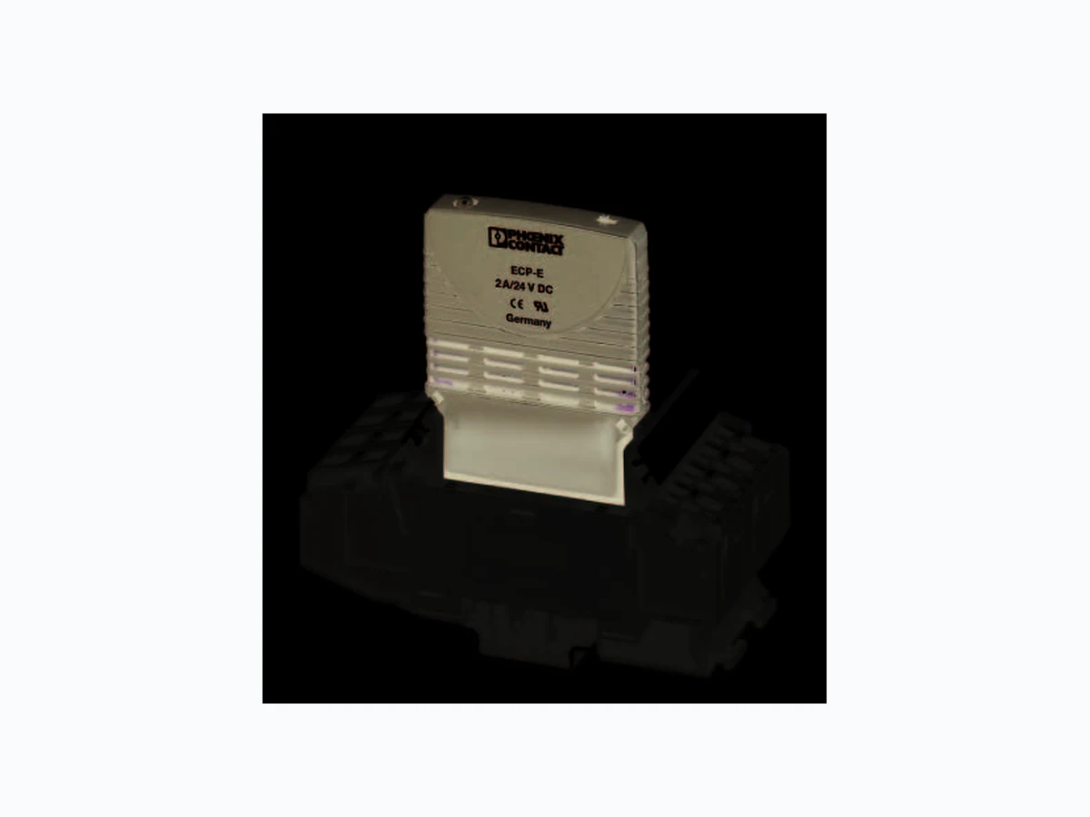
© PHOENIX CONTACT 2010-12-17102898_en_03 CLIPLINE ECP-E… Data sheet 1D e s c r i p t i o n The ECP-E… electronic circuit breaker can be used in applications that cover all aspects of the switched-mode power supply unit. In the event of an overload, switched-mode power supply units reduce their output voltage, which means that all the connected loads are no longer sufficiently supplied, e.g., in the event of a short circuit at the load. The solution here is the ECP-E… electronic circuit breaker, which selectively protects all 24 V DC load circuits. The ECP-E… constantly limits the re sidual current to 1.8 times (or 1.5/1.3 times) the protected nominal current. Capacitive loads can thus be switched on and loads are only switched off in the event of an overload or short circuit. After detecting an overload or short circuit in the load circuit, the load output of the ECP-E… is disabled. The current flow in the faulty circuit is interrupted. The ECP-E… and therefore the circuit can be activated again via the electronic reset input (13;14) or manually on the device via the slide switch. A multi-color LED and the integrated status output (12) indicate the operating or error state. The ECP-E… offers quick and space-saving assembly, as it can be plugged onto the TMCP SOCKET M and has a low design width of just 12.5 mm.
1.1 Properties
– Selective load protection, electronic shutdown characteristic curve – Active current limitation when switching on capacitive loads up to 20,000 µF and in the event of overload/short circuit – Nominal current can be selected in fixed current strengths from 1 A ... 12 A – Safe overload shutdown from 1.1 x I N, even for long load cables or low cable cross-sections – Manual on/off switch (S1) –I n d i c a t i o n b y m e a n s o f LED, status output SF – Electronic reset input RE – Integrated failsafe element – Design width of just 12.5 mm per channel – Can be plugged into a modular base NOTE: Make sure that the cable cross-section of the relevant load circuit is adapted to the nominal current of the ECP-E… used. In the system or machine, take special precautionary measures to prevent system parts from restarting (according to Machinery Directive 2006/42/EC and EN 60204-1). In the event of an error (short circuit/overload), the load circuit is electronically shut down by the ECP-E…. NOTE: Make sure that the cable cross-section of the relevant load circuit is adapted to the nominal current of the ECP-E… used. Make sure you always use the latest documentation. It can be downloaded at www.phoenixcontact.net/catalog This data sheet is valid for all products listed on the following page: Electronic circuit breaker
ECP-E… 102898_en_03 PHOENIX CONTACT 2 2O r d e r i n g d a t a Electronic circuit breaker Description Type Order No. Pcs./Pkt. Electronic circuit breaker, standard version with status output and reset input, can be plugged into a TMCP base, indication by means of 3-color LED
1 A nominal current ECP-E 1A 0900113 5
2 A nominal current ECP-E 2A 0900210 5
3 A nominal current ECP-E 3A 0900317 5
4 A nominal current ECP-E 4A 0900414 5
6 A nominal current ECP-E 6A 0900618 5
8 A nominal current ECP-E 8A 0900812 5
10 A nominal current ECP-E 10A 0901002 5
12 A nominal current ECP-E 12A 0900126 5
Description Type Order No. Pcs./Pkt. Modular base, 2-pos., designed to accommodate two 1-pos. circuit breakers, width of 12.5 mm per position TMCP SOCKET M 0916589 10 Base termination elements, can be plugged into both the left and right-hand side, contain the connections for the reset inputs/group query TMCP CONNECT LR 0916592 3 Spring lock, for mechanical locking if mounted overhead, 1-pos. ECP-LOCK 0912021 10 Zack marker strip, 10-section, for labeling the center of the terminal block ZB 6 See CLIPLINE catalog Fixed bridge, plug-in, not insulated, 500 mm long, can be cut to length, for distribution of the supply potential in the base, Imax = 50 A FBST 500 TMCP 0916615 20 Continuous plug-in bridge, 500 m long, can be cut to length, for potential distribution, Imax = 32 A, red FBST 500-PLC RD 2966786 20 Continuous plug-in bridge, 500 m long, can be cut to length, for potential distribution, Imax = 32 A, blue FBST 500-PLC BU 2966692 20 Signal bridge, plug-in, for bridging group indication when there is a free slot on the TMCP SOCKET M base, Imax = 1 A TCMP SB 0916602 6
ECP-E… 102898_en_03 PHOENIX CONTACT 3
3 Technical data
DC supply voltage 18 V DC ... 32 V DC Nominal current IN Depending on the selected item version:
1 A, 2 A, 3 A, 4 A, 6 A, 8 A, 10 A, 12 A
Closed circuit current I0 In the ON state: 20 mA ... 30 mA, typical (depending on the signal output) Tripping current (bimetal) 0.3 A, typical (only in th e event of an error, until electrically shut down) Indication of the operating state – Multi-color LED – Status output SF – On/off position of switch S1 Multi-color LED Green = Device switched on (S1 = ON) or load circuit/Power MOSFET controlled Orange = Overload or short circuit until electronically shut down Red = Device electronically shut down, load circuit/Power MOSFET switched off, undervoltage (U B < 8 V) or after switch-on until the end of the switch-on delay time OFF: Manually switched off (S1 = OFF) or device power supply disconnected Protection against polarity reversal of UB Internal bimetal (failsafe element) triggered, pushbutton moves to OFF position Auxiliary contacts Pin 11 (GND) Pin 12 (individual indication) Pin 13/14 (group query) Switching capacity ICN Active current limitation of 180% Load circuit Load output Power MOSFET output (positive switching) Short circuit current IK Active current limitation; 1.8 x IN, maximum (see "Time-current characteristic" on page 6) Shutdown time 3 s at IL > 1.1 x IN, typical See "Voltage drop, current limitation, maximum load current" on page 4 Ri when plugged in = 50 m Temperature shutdown Internal temperature monitoring with electronic shutdown Undervoltage monitoring of load output With hysteresis, no reset required: OFF at UB < 8 V Switch-on delay tStart 0.5 s, typical after each switch-on and after applying UB Load circuit shutdown Electronic shutd own after overload/short circuit Free running circuit External free-wheeling diode recommended on inductive load Parallel connection of multiple load outputs Not permitted Status output Electrical data Positive switching signal output, switches UB on pin 12 of TCMP SOCKET M base, nominal data: 24 V DC/0.2 A, maximum (short-circuit-proof) The status output is internally terminated to ground using a 10 kOhm resistor. Status OUT ECP-E… (signal status OUT), at U B = +24 V +24 V = S1 is ON, load output switched through
0 V = S1 is ON, load output disabled and/or switch S1 is OFF
OFF state 0 V level always present at status output if: – Switch S1 is set to ON, but device is still in the switch-on delay phase – Switch S1 is set to OFF or control signal is OFF, device is switched off – Operating voltage U B is not present
ECP-E… 102898_en_03 PHOENIX CONTACT 4 Reset input Electrical data Maximum voltage +32 V DC High > 8 V DC ≤ 32 V DC Low ≤ 3 V DC > 0 V DC Current consumption 2.6 mA, typical (+24 V DC) Minimum pulse length 10 ms Reset signal RE (pin 12 of base) With the falling edge of a +24 V DC pulse, the electronically disabled ECP-E… can be switched on again remotely via an external button. This reset signal is supplied in pin 12 of the base and is internally prewired. On the ECP-E…, the reset simultaneously affects all disabled channels of the current distributor. Activated channels remain unaffected. WARNING: Always fill empty slots with the signal bridge. General data Width x length x height 12.5 mm x 60 mm x 70 mm Weight 40 g Service life at 1 x IN 10,000 Ambient temperature 0°C ... +50°C (no condensation, see EN 60204-1) Storage temperature -20°C ... +70°C Insulation material PA-F Inflammability class according to UL 94 V0 Backup fuse Not required, since a redundant failsafe element is integrated. If the failsafe element has been triggered, the pushbutton is in the OFF position. Housing fixing Can be plugged into TMCP SOCKET M modular base Slip-on connections 6.3 mm according to DIN 46244-A6.3-0.8 Humid heat 96 h/95% relative humidity/40°C according to IEC 60068-2-78, Test Cab climatic class 3K3 according to EN 60721 Degree of protection Housing: IP30, DIN 40050 Terminal blocks: IP00, DIN 40050 Tests/approvals Conformance with EMC Directive 2004/108/EC Noise emission: EN 61000-6-3 Noise immunity: EN 61000-6-2 Isolation coordination (IEC 60934) 0.5 kV/pollution degree 2, increased isolation in the actuation area Dielectric strength 32 V DC, maximum (load circuit) Insulation resistance (OFF state) None, electronic shutdown only Vibration resistance 3g, test according to IEC 60068-2-6 Test Fc Approvals u UL 2367, File E317172 Solid State Overcurrent Protectors c Voltage drop, current limitation, maximum load current Nominal current IN Typical voltage drop UON at IN Active current limitation (typical) Maximum load current at 100% operating factor, TA = 40°C Maximum load current at 100% operating factor, TA = 50°C 1 A 80 mV 1.8 x IN 1 A 1 A 2 A 130 mV 1.8 x I N 2 A 2 A 3 A 80 mV 1.8 x IN 3 A 3 A 4 A 100 mV 1.8 x I N 4 A 4 A 6 A 130 mV 1.8 x IN 6 A 5 A 8 A 120 mV 1.5 x I N 8 A 7 A 10 A 150 mV 1.5 x IN 10 A 9 A 12 A 180 mV 1.3 x I N 12 A 10.8 A When mounted in rows without convection cooling, due to the thermal effect during continuous operation (100% operating factor) the nominal device current must only be led to a maximum of 80%.
ECP-E… 102898_en_03 PHOENIX CONTACT 5
3.1 Connection diagram
3.2 Block diagram (example ECP-E ...) Figure 1 Block diagram (example ECP-E ...)
3.3 Dimensions
Figure 2 Dimensions (in mm) The signal contacts are shown in the OFF or error state. With reset input RE (+24 V DC0), with status output SF (+24 V = Load output ON) Normal state: SF +24 V = OK Error state: SF 0 V Control Unit Operating Status Green/Orange/Red Reset Input Reset Input Status Output Snap-on lock Actuation area Installation area Flat connector
ECP-E… 102898_en_03 PHOENIX CONTACT 6
3.4 Time-current characteristic (T A = 25°C)
Figure 3 Time-current characteristic is 3 s. – The electronic current limit ation is typically activated from 1.8 x IN*. This means that under all overload conditions (regardless of the current supply and load circuit resistance), 1.8 times the nominal current* typically flows until shutdown. The shutdown time ranges from 100 ms to 3 s depending on the multiple of the nominal current or in the event of short circuit (IK). – Without the current limitat ion typically activated at 1.8 x IN*, a significantly higher overcurrent would flow in the event of an overload or short circuit. * Typical current limitation 1.8 x I N at IN = 1 A ... 6 A Typical current limitation 1.5 x IN at IN = 8 A or 10 A Typical current limitation 1.3 x IN at IN = 12 A Stop point typ. 1,1 x l 1 , 8xl Switching tim e [s] Multiples of IN N N 0,01 0,1 102 3 IK
ECP-E… 102898_en_03 PHOENIX CONTACT 7
3.5 Safe shutdown
Safe shutdown of the ECP-E… for various supply line lengths and cable cross-sections Specific electrical resistance of electrolytic copper ρ0 = 0.0178 ( x mm²)/m UB = 19.2 V DC (80% of 24 V DC) The voltage drop at the EC P-E… and the tolerance of the shutdown point ECP-E… nominal current setting I N (in A) 3 A 6 A Rmax in Ohm = (UB/Ioff) - 0.050 1
1 Internal resistance of miniature circuit breakers
5.07 2.51 ECP-E… safely trips from 0 up to maximum circuit resistance Rmax Distance L in meters (= single length) 0 Total cable resistance in Ohm = (R0 x 2 x L)/A 0000000 Example 1: Maximum permissible distance for 1.5 mm² and 3 A Approximately 200 m2 2 Shutdown current Ioff = 3 A x 1.25 A = 3.75 A Maximum circuit resistance Rmax = UB/Ioff - 0.050 (internal resistance of miniature circuit breakers) In the table, the calculated value of 5.07 lies between 200 m and 225 m (4.75 and 5.34 ). Therefore a distance of around 200 m can be covered. Example 2: Maximum permissible distance for 1.5 mm² and 6 A Approximately 100 m Example 3: Mixed wiring: (Control cabinet --- sensor/actuator level) R1 = 40 m in 1.5 mm² and R2 = 5 m in 0.25 mm² R1 = 0.95 Ohm, R2 = 0.71 Ohm Total (R1 + R2) = 1.66 Ohm
ECP-E… 102898_en_03 PHOENIX CONTACT 8
4 Mounting on a modular base
The TMCP SOCKET M base is snapped onto a DIN rail and can accommodate two ECP-E… devices. The two-channel bases are modular, which means that larger distribution systems can be created. A connection element is inserted at both the start and end of the system. Current distribution on the individual channels with a common supply (positive pole) is achieved by inserting a power rail in the slot provided on the connection side of the modules. All electrical connections are established using spring-cage terminal blocks. The reference potential for the ECP-E… (GND pin 11) is also looped through and led to the side connection elements. By connecting together the individual bases, all the internal wiring is established for the ground potential and group error message. The ECP-E… has an integrated signal contact (PDT). The SC-S0 contact is used for the group error message. The contacts for this indication are already connected in series in the bases and are connected to the side connection elements via two connections (13, 14). In each base, the series circuit can be contacted using a test socket and any interruptions can thus be determined.
4.1 Technical data
4.2 Dimensions with base
Test contact for testing group indication on a cable interrupt ø = 2 mm Nominal voltage (without ECP-E…) 433 V AC; 65 V DC Nominal current (without ECP-E…) LINE supply (1) LOAD output (2) Reference potential GND (11) Individual indication (12) Group indication (13-14) 50 A 25 A 10 A 1.0 A (with ECP-E…: 0.5 A) 1.0 A (with ECP-E…: 0.5 A) Internal resistance (without ECP-E…) LINE-LOAD (1-2) Indication (13-14) for each module 5 m 8 m/each position plus each additional aligned module: +5 m Supply rail for current distribution Uninsulated power rail I max 50 A (the uninsulated power rail is inserted fully and is therefore safe to touch) Dielectric strength of base (without ECP-E….) Between main circuits (without power rail) Main circuit to signal circuit Signal circuit to signal circuit 1500 V 1500 V 1500 V Weight Central part Connection elements (pair) 85 g, approximately 30 g, approximately Approval Meets standard UL 60950
ECP-E… 102898_en_03 PHOENIX CONTACT 9
4.3 Assembly
To assemble, proceed as follows:
- Snap TMCP SOCKET M base onto an NS 35 DIN rail according to EN 60751.
- Push bases together.
- Snap on TMCP CONNECT LR base termination elements to the left and right-hand side.
- Cut FBST 500... power rail to length as required and insert in bases.
- Insert connecting cables in the spring-cage terminal blocks (see "Connecting spring-cage terminal blocks" on page 9 and "Pin assignment on base" on page 9).
- Insert ECP-E….
- If necessary, secure the ECP-E… and base using a clamp (see "Locking the base and ECP-E…" on page 10).
4.4 Connecting spring-cage terminal blocks
Spring-cage terminal blocks for solid wires and stranded cables with and without ferrules. Use the specified screwdriver size (SD) to release the spring cage.
4.5 Pin assignment on base
Figure 6 Connection diagram Figure 7 Pin assignment WARNING: Always fill empty slots with the TMCP SB signal bridge. Base termination element Modular bases Base termination element Electronic circuit breaker Connection Spring-cage terminal blocks for Screwdriver size (SD) Reference potential GND or group indication connections (11 or 13, 14) Individual indication connection (12) PIN Assignment
11 GND
12 Status message SF +24 V = OK
13, 14 Reset input RE (group reset) +24 V falling edge WARNING: Always fill empty slots with the TMCP SB signal bridge. Side supply TMCP CONNECT LR TMCP CONNECT LR TMCP SB FBST 500 ... ECP-E… TMCP SOCKET M TMCP SOCKET M ECP-E… TMCP SOCKET M[2(k)] LINE (+) [12] GND [24] Reset IN+, +24 V [2(i)] Not used [23] Reset IN+, +24 V [11] Status OUT, +24 V = OK [1] LOAD (+)
ECP-E… 102898_en_03 10PHOENIX CONTACT GmbH & Co. KG • 32823 Blomberg • Germany • Phone: +49 - 52 35 - 30 0 PHOENIX CONTACT • P.O.Box 4100 • Harrisburg • PA 17111-0100 • USA • Phone: +717-944-1300 www.phoenixcontact.com
4.6 Locking the base and ECP-E…
If mounted overhead, the ECP-E… must be connected to the base using the ECP-LOCK clamp. Figure 8 Mounting the ECP-LOCK Figure 9 Removing the ECP-LOCK