
DATASHEET SEARCH SITE
Document overview
- Manufacturer or author: Provided By digicamel.com
- PDF pages: 15
Technical content
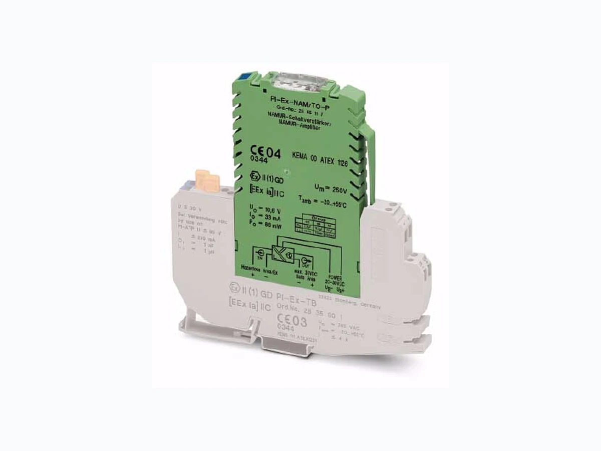
© PHOENIX CONTACT 2009-11-11102098_en_04 INTERFACE PI-EX-NAM/TO-P Data Sheet 1D e s c r i p t i o n The PI-EX-NAM/TO-P is a 3-way isolation amplifier. It is designed to operate proximity switches according to EN 60947-5-6 as well as switch contacts with open circuit and resistance circuit. The signals from the Ex area are electrically isolated and transmitted to a control system located within the safe area via a transistor. At the output side, the isolation amplifier has a passive short-circuit-proof NPN transistor that is electrically isolated from the sensor and supply sides. The module itself is installed outside the Ex area or in zone 2. The PI-EX-NAM/TO-P features line fault detection (LFD, see page 7), which can be switched on/off via a switch depending on the application. If a line fault is detected or a supply voltage failure occurs, the module switches to the OFF state, i.e., the transistor output is blocking. As an option, the PI-EX-NAM/TO-P can also be operated in the inverted direction. A switch is also used to switch between normal and inverse mode. Both switches are located on the front of the device and can be operated after opening the transparent cover.
1.1 Properties
– Single-channel – Input for NAMUR proximity se nsor or switch, [Ex ia] IIC – Transistor output (passive) – Installation in zone 2 – 20 V DC ... 30 V DC supply – Option of phase reversal – Line fault detection (LFD) – 3-way electrical isolation – SIL 2 according to IEC 61508 NOTE: Devices manufactured in 2005 or later meet the requirements for SIL 2 (see device labeling: CE mark in conjunction with the date). Please refer to the instructions in Section 9. WARNING: Explosion hazard The device is an associated item of equipment. It is designed for use in zone 2, if the specific conditions are observed. When installing and operating the device, the applicable safety directives (including national safety directives), accident prevention regulations, as well as general technical regulations, must be observed. WARNING: Explosion hazard Observe the safety regulations and installation notes on page 5. Make sure you always use the latest documentation. It can be downloaded at www.phoenixcontact.net/download. This data sheet is valid for all products listed on the following page: Ex-i NAMUR Isolation Amplifier With Passive Transistor Output
102098_en_04 PHOENIX CONTACT 2 Table of Contents 2O r d e r i n g D a t a NAMUR Isolation Amplifier Description Type Order No. Pcs./Pck. Ex-i NAMUR isolation amplifier with passive transistor output PI-EX-NAM/TO-P 2865117 1 Accessories Description Type Order No. Pcs./Pck. Motherboard See "INTERFACE" catalog Ex basic terminal block for intrinsically safe signals with knife disconnection and test connections PI-EX-TB 2835901 10 Intrinsically safe basic terminal block, with knife disconnection, test connections, and surge protection, for mounting on NS 35/7,5 TT-PI-EX-TB 2858386 10 Basic terminal block for non-intrinsically safe signals, with surge protection TT-PI-TB 2858373 10 Basic terminal block for non-intrinsically safe signals, without surge protection PI-TB 2835943 10 Continuous plug-in bridge, 500 mm long, insulated, can be cut to length, for potential distribution, Imax = 32 A, color of the insulating material: Red Blue Gray FBST-500-PLC-RD FBST-500-PLC-BU FBST-500-PLC-GY 2966786 2966692 2966838 For additional accessories, please refer to the "INTERFACE" catalog from Phoenix Contact.
102098_en_04 PHOENIX CONTACT 3
3 Technical Data
Input Intrinsically safe, designed for protection type "i" [Ex i] Available input sources – NAMUR proximity switches according to EN 60947-5-6 – Switch contacts wi th open circuit (not for safety-related applications, SIL 2) – Switch contacts with resistance circuit (series resistance 1 kΩ ±10%, parallel resistance 10 kΩ ±10%) Control Circuit Non-load voltage 8.2 V DC ±10% Switching points according to EN 60947-5-6 Blocking Conductive I < 1.2 mA I > 2.1 mA Switching hysteresis 150 μA, approximately Line fault detection Activated/deactivated via switch Cable break detection I < 0.05 mA Short-circuit detection: Operating range R (according to EN 60947-5-6) 100 Ω ... 360 Ω Output Transistor (terminal block 3, 4) Passive transistor switching output (NPN transistor) with electrical isolation from sensor and supply sides Maximum output current 100 mA (short-circuit-proof) External switching voltage U/ΔU 10 V DC ... 30 V DC/1.5 V Switching behavior Can be inverted via switch (not with SIL) Switching frequency DC, 2 kHz, maximu m (with pulse-duty factor of < 4:1) General Data Supply voltage range 20 V DC ... 30 V DC Nominal operating voltage 24 V DC Current consumption 25 mA Power dissipation 0.6 W, maximum (at 24 V) Supply voltage type External Electrical isolation Input/output Input/supply
375 V (peak value according to EN 50020)
Test voltage (input/output and input/supply) 1.5 kV AC, 50 Hz, 1 minute Housing material PBT and polyamide PA, non-reinforced Inflammability class according to UL 94 V0 Degree of protection IP20 Color Green Dimensions Without basic terminal block (width x height) With basic terminal block (width x height x length) 12.4 mm x 108.6 mm 12.4 mm x 147 mm x 145 mm NAMUR recommendation NE 21 Ambient Conditions Ambient temperature (operation) -20°C ... +5 5°C (perpendicular mounting of DIN rail) -20°C ... +60°C (horizontal mounting of DIN rail) Average temperature according to IEC 61508 ≤ +40°C Ambient temperature (storage/transport) -40°C … +80°C Permissible humidity (operation and storage/transport) 10% ... 95% (relative humidity, no condensation) Vibration 2g (according to DIN EN 60068-2-26) Shock 15g (according to DIN EN 60068-2-27)
102098_en_04 PHOENIX CONTACT 4 Height (installation location) 2000 m above sea level, maximum Height (storage location) 3500 m above sea level, maximum Protection against water and dust IP20 Ambient Conditions (Continued) Indicators Status indicator Green LED (supply voltage) Yellow LED (switching state of the transistor output) Red LED (line fault on the sensor cable, transistor blocking) When using the PI-EX-NAM/TO-P in safety-related applications, observe the technical data on page 12, as the requirements differ for safety-related functions. EC Conformance EMC directive 89/336/EEC Yes Ex directive (ATEX) Yes Safety Data According to ATEX for Intrinsically Safe Circuits Maximum output voltage Uo 10.6 V Maximum output current Io 33 mA Maximum output power Po 86 mW Gas group Maximum external inductance Lo Maximum external capacitance Co II A 230 mH 72.0 μF II B 110 mH 16.2 μF II C 30 mH 2.3 μF Um 250 V AC Approvals ATEX X II (1) GD [Ex ia] IIC, KEMA 00 ATEX 1126 X II 3G Ex nA II T4X UL/CUL In preparation
102098_en_04 PHOENIX CONTACT 5
4 Safety Regulations and Installation Notes
4.1 Installation and Operation
Follow the installation instructions. When installing and operating the device, the applicable safety directives (including national safety directives), accident prevention regulations, as well as general technical regulations, must be observed. Do not repair the device yourself, replace it with an equivalent device. Repairs may only be carried out by the manufacturer. In order to provide protection against mechanical or electrical damage, install the device in corresponding housing with a suitable degree of protection according to IEC 60529.
4.2 Safety Regulations for Installation in
Potentially Explosive Areas Regulations for Intrinsically Safe Circuits For the safety data, please refer to the operating instructions and certificates (EC-type examination, other approvals, if necessary). Installation in Zone 2 Observe the specified conditions for use in potentially explosive areas. Installation in Areas With a Danger of Dust Explosions Connection to the intrinsically safe circuit in areas with a danger of dust explosions (zone 20, 21, and 22) is only permitted if the equipment connected to this circuit is approved for this zone (e.g., category 1D, 2D or 3D).
4.3 Use in Safety-Relat ed Applications (SIL 2)
When using the PI-EX-NAM/TO-P in safety-related applications, observe the instructions in Section 9, as the requirements differ for safety-related functions. NOTE: Installation, operation, and maintenance may only be carried out by qualified specialist personnel. NOTE: The circuits inside the device must not be accessed. NOTE: The device is designed to meet IP20 protection when: – It is installed outside potentially explosive areas. – The environment is clean and dry. WARNING: Explosion hazard When carrying out measurements on the intrinsically safe side, observe the relevant regulations regarding the connection of intrinsically safe equipment. Only use devices approved for use in intrinsically safe circuits. WARNING: Explosion hazard If the device has been used in non- intrinsically safe circuits, it must not be used again in intrinsically safe circuits. The module must be clearly labeled as non- intrinsically safe. WARNING: Explosion hazard The device is an associated item of equipment with "intrinsically safe" explosion protection and is designed for installation in zone 2, if the symbol is printed on the block. WARNING: Explosion hazard Install the device in suitable housing that meets IP54 protection, minimum. Observe the requirements of IEC 60079-14/EN 60079-14, e.g., steel housing with a wall thickness of 3 mm. WARNING: Explosion hazard Disconnect the block power supply before: – Snapping it on or disconnecting it. – Connecting or disconnecting cables of non-intrinsically safe circuits. WARNING: Explosion hazard Only use category 3G PI EX modules (ATEX 94/9/EC). WARNING: Explosion hazard The device is not designed for use in areas with a danger of dust explosions.
102098_en_04 PHOENIX CONTACT 6
5 Structure
1 Input "+"
2 Input "–"
3 Output "+"
4 Output "–"
1 - 4 Terminal screw with integrated test socket
5 Voltage supply "+", UB+
6 Voltage supply "–", UB–
7 Isolating connectors
8 Test socket
9 Locking clip
0 Keying pin
! Switch (LF/NLF and N/I) Dimensions Figure 2 Dimensions (in mm)
6 Installation
6.1 Base Elements
The device is designed for installation in the control cabinet and must be plugged into a base element (basic terminal block, electronics base or motherboard). Incorrect connection of the electronic module is prevented by a keyway in the base element and bars in the housing. A locking clip 9 is provided to prevent accidental removal of the device. To remove the electronic module, gently press the locking clip towards the housing; it can then be removed. IN OUT +-- ++ - 7 4 PI-EX-NAM/TO-P PWR STATLF NLF LF N I 1010 UB+ UB- UB+ UB- UB+ UB- PI-EX-NAM/TO-P The PI-EX-NAM/TO-P can be installed in safe areas or in zone 2. PI-EX-TB basic terminal block 145 12.4 147 86.5 PI-EX-NAM/TO-P Basic terminal block NOTE: Electrostatic discharge The device contains components that can be damaged or destroyed by electrostatic discharge. When handling the device, observe the necessary safety precautions against electrostatic discharge (ESD) according to EN 61340-5-1 and EN 61340-5-2. WARNING: Explosion hazard When used as equipment in zone 2, the electronic module must not be disconnected from the base element when connected to the power supply. Cables of non-intrinsically safe circuits must only be connected and disconnected when the power is disconnected. WARNING: Explosion hazard If the device has been used in non-intrinsically safe circuits, it must not be used again in intrinsically safe circuits. The module must be clearly labeled as non-intrinsically safe. Connection cross-section (solid/stranded): 0.2 mm 2 ... 2.5 mm2
102098_en_04 PHOENIX CONTACT 7
6.2 Automatic Keying of Electronic Modules
The base element is not keyed by default upon delivery. The user-friendly keying is located in the electronic module and consists of four plastic parts, which are joined together. When the electronic module is first removed, the lower part of the keying pins (0 in Figure 1 on page 6) remains in the base element. In this way, it is automatically keyed to the relevant electronic module. If an electronic module is accidentally inserted in the wrong place, any plastic parts remaining in the base element can be removed using a screwdriver.
7 Configuration
By default upon delivery, line fault detection is disabled and the normal phase function is enabled.
7.1 Line Fault Detection (LF/NLF Switch)
Line fault detection is enabled or disabled using a switch (see Figure 3, disabling is not permitted for safety-related applications, SIL 2). When line fault detection is enabled, the transistor blocks so that the output is set to the safe, non-conductive state. The red LED (LF) lights up.
7.2 Phase Reversal
The phase reversal function is enabled or disabled using a switch (see Figure 3). Automatic keying Electronic module Base element View from below (locking clip to the right) View from above (isolating connector to the left) Input Output Input Output PI-EX-NAM/TO-P LF = Line fault detection enabled NLF = Line fault detection disabled (not permitted for safety-related applications, SIL 2) N = Normal function I = Inverse function PWR = Supply voltage STAT = Transistor ou tput switching status LF = Line fault on the sensor cable Operating range for the cable break alarm: 50 μA > I > 350 μA Operating range for the short-circuit alarm: 100 Ω > R > 360 Ω NOTE: For switch contacts with open circuit (Figure 4) line fault detection (LF) must be disabled or the corresponding resistance circuit must be provided directly at the switch contact (Figure 5, e.g., UKK 5-2R/NAMUR (Order No. 2941662) with D-UKK 3/5 (Order No. 2770024)). PI-Ex-NAM/RNO PWRSTATLF NLF LF N I Figure 4 Switch contact with open circuit (not permitted for safety-related
applications
(SIL 2)) Figure 5 Switch contact with resistance circuit Normal Phase Inverted Phase Output transistor conductive, if I > 2.1 mA Output transistor blocking, if I > 2.1 mA Output transistor blocking, if I < 1.2 mA Output transistor conductive, if I < 1.2 mA 10 kΩ 1 kΩ
102098_en_04 PHOENIX CONTACT 8
7.3 Truth Table for Non-Sa fety-Related Applications
8 Comparison of Safety Data
Safety data of: For the values for Uo, Io, Po, Lo, and Co, please refer to "Safety Data According to ATEX for Intrinsically Safe Circuits" on page 4. Ex i Requirements: NOTE: This truth table does not apply to safety-related applications according to IEC 61508 (SIL 2). For the truth table for SIL 2 applications, please refer to page 10. Sensor in Input Input Switch Output ST LED LF LEDSwitch Open Circuit Resistance Circuit NAMUR N I NLF LF Transistor Yellow Red Open Open Blocking OK X X Non-conductive Closed Closed Conductive OK X X Conductive X Any Any Any Open circuit X X Non-conductive Any Any Any Short circuit X X Conductive X Open Open Blocking OK X X Conductive X Closed Closed Conductive OK X X Non-conductive Any Any Any Open circuit X X Conductive X Any Any Any Short circuit X X Non-conductive Open Blocking OK X X Non-conductive Closed Conductive OK X X Conductive X Any Any Open circuit X X Non-conductive X Any Any Short circuit X X Non-conductive X Open Blocking OK X X Conductive X Closed Conductive OK X X Non-conductive Any Any Open circuit X X Non-conductive X Any Any Short circuit X X Non-conductive X WARNING: Explosion hazard Compare the safety data before connecting a device located in the Ex-i area to the PI-EX-NAM/TO-P. Field devices: U i, Ii, Pi, Li, Ci NAMUR isolation amplifiers: U o, Io, Po, Lo, Co Ui ≥ Uo Ii ≥ Io Pi ≥ Po Li + Lc ≤ Lo (Lc and Cc depend on the cables/lines used)Ci + Cc ≤ Co
102098_en_04 PHOENIX CONTACT 9
9 Safety-Related Applications (SIL 2)
9.1 Installation
Use one of the following base elements: – PI-EX-TB basic terminal block – TT-PI-EX-TB... basic terminal block – PI-EX-MB... motherboard
9.2 Wiring
Permitted for safety-related applications: – NAMUR sensor (according to EN 60947-5-6) – Switch contact with resistance circuit (1 k Ω serial and 10 kΩ parallel (tolerance ±10%)) (Note: The resistance circuit regulates the behavior of a NAMUR sensor) Output The safety-related function at the output depends on the "N/I" switch position.
9.3 Diagnostic Function of the "LF/NLF" Switch
For safety applications, line fault detection is enabled, i.e., the slide switch is in the "LF" position. When line fault detection is enabled, the red LED indicates any faults that occur. If a line fault is detected, the output is disabled ("non-conductive"). This behavior is independent of the position of the "N/I" switch.
9.4 Safe State
The "safe state" means that the output is in a non-conductive state, i.e., the transistor is blocking. WARNING: Switch contacts without resistance circuit are not permitted for safety-related applications. N = Normal function In the event of a 0 signal (NAMUR sensor high resistance, therefore lower current in the input circuit), the output (transistor) switches to the "non-conductive" state. I = Inverse function In the event of a 1 signal at the input, the output switches to the "non-conductive" state. WARNING: The "NLF" switch position is not permitted for safety-related applications.
102098_en_04 PHOENIX CONTACT 10
9.5 Truth Table for Safety-R elated Applications (SIL 2)
WARNING: Only the "LF" switch position is permitted for safety-related applications. WARNING: Only switch contacts with resistance circuit are permitted at the input for safety-related applications (see Figure 5 on page 7). Sensor in Input Input Switch Output ST LED LF LED Permitted for Safety-Related NAMUR N I NLF LF Relay Yellow Red Open Blocking OK X X Non- conductive Yes Closed Conductive OK X X Conductive X Yes Any Any Open circuit X X Non- conductive XY e s Any Any Short circuit X X Non- conductive XY e s Open Blocking OK X X Conductive X Yes Closed Conductive OK X X Non- conductive Yes Any Any Open circuit X X Non- conductive XY e s Any Any Short circuit X X Non- conductive XY e s PI-Ex-NAM/RNO PWRSTATLF NLF LF N I LF = Line fault detection enabled NLF = Line fault detection disabled (not permitted for safety-related applications, SIL 2) N = Normal function I = Inverse function PWR LED = Supply voltage STAT LED = Switching state of the relay output LF LED = Line fault on the sensor cable
102098_en_04 PHOENIX CONTACT 11
9.6 Response Times
Following a state change at the input, the output enters the safe state in ≤ 40 ms.
9.7 Operating Mode of the Safety Function
Operating mode according to IEC 61508: "Low demand mode".
9.8 Failure Behavior and Required Response
- The safe state is entered in the event that a line fault is detected or the supply voltage fails (see Section 9.4). 2. The safe state is reached by removing the device from the base element. Startup and Restart Behavior Description Startup or restart of the device The output enters the state without oscillation (according to the truth table on page 10). A reset is not required. What happens when a line fault is detected and what must the user do? The fault is indicated by the red LED and the output enters the "non-conductive" state regardless of the input signal and the operating mode (normal or inverse mode). The user must remove the line fault (short circuit or break in the sensor cable). The device output is not blocked when fault detection is triggered (no lock or reset). Undefined line states that occur during repairs can switch the output. This must be prevented by the user by disconnecting the supply voltage or by removing the device. Other options that have the same result and do not present an additional hazard are permitted. The line fault is removed. The user must ensure that a de fined state is entered using the truth table on page 10. The device is restarted as with initial startup. The device then behaves as described under "Startup or restart of the device".
102098_en_04 12PHOENIX CONTACT GmbH & Co. KG • 32823 Blomberg • Germany • Phone: +49 - 52 35 - 30 0 PHOENIX CONTACT • P.O.Box 4100 • Harrisburg • PA 17111-0100 • USA • Phone: +717-944-1300 www.phoenixcontact.com
9.9 Safety Integrity Requirements
– Type A device (according to IEC 61508-2) – Safety Integrity Level (SIL) 1 and 2 PFDAVG Values The box marked in white means that the calculated PFDAVG values are within the permitted range for SIL 2 according to table 2 of IEC 61508-1, but do not meet the requirement to not claim more than 10% of this range, i.e., to not be better than or equal to 1,00E-03. The boxes marked in gray mean that the calculated PFD AVG values are within the permitted range for SIL 2 according to table 2 of IEC 61508-1, but do meet the requirement to not claim more than 10% of this range, i.e., to be better than or equal to 1,00E-03. Failure Limit The operating mode is based on low demand mode. The percentage of the device at PFH/PFD for the overall safety loop is 10%. Figure 6 Safety loop Conditions – Line fault detection is active. – The failure rates of the components used remain constant throughout the period of use. – Propagation of errors by the device in the system is not taken into consideration. – The repair time (= replac ement) should take eight hours. – The failure rates of the external power supply are not taken into consideration. – The average temperature at which the device is to be used is +40°C. This is based on standard industrial conditions. – At an average temperature of +60°C, the error rates should by multiplied by 2.5 (guide value). – A multiplier must also be used in the event of frequently fluctuating temperatures.
9.10 Proof Test
- Carry out the appropriate steps to prevent incorrect use. 2. An appropriate signal is applied at the input of the PI-EX-NAM/TO-P NAMUR switching amplifier in order to obtain the non-conductive state at the output. Check whether the output is non-conductive. 3. Restore the full functions of the safety circuit. 4. Restore normal mode. With this test around 99% of possible "du" ("dangerous undetected") errors are uncovered in the NAMUR isolation amplifier.
10 Appendix
Exida Assessment Summary (3 pages) λsd λsu
1 The SU (Safe Undetected) category includes failures that do not
cause a spurious trip. λdd λdu SFF2
2 SFF = Safe Failure Fraction
3 DC = Diagnostic Coverage (safe or dangerous)
6 FIT4
4 FIT = Failure in Time (1 FIT = 1 failure/109 h)
183 FIT 8 FIT 37 FIT 84% 3% 17%
T[PROOF] = 1 year 5 years 10 years PFDAVG 1 =
1 PFD = Probability of Failure on Demand
1,62E-04 8,08E-04 1,62E-03 Sensor 25% Switching amplifier 10% Processing 15% Actuator 50%
The document was prepared using best effort. The authors make no warranty of any kind and shall not be liable in any event for incidental or consequential damages in connection with the application of the document. © All rights on the format of this technical report reserved. Failure Modes, Effects and Diagnostic Analysis Project: NAMUR Switching Amplifiers PI-Ex-NAM/RNO-NE and PI-Ex-NAM/TO-P Customer: PHOENIX CONTACT GmbH & Co. KG Blomberg Germany Contract No.: Phoenix Contact 05/10-12 Report No.: Phoenix Contact 05/10-12 R002 Version V1, Revision R1.1, March 2006 Stephan Aschenbrenner
© exida.com GmbH phoenix contact 05-10-12 r002 v1 r1.1.doc, March 8, 2006 Stephan Aschenbrenner Page 2 of 3 Management summary This report summarizes the results of the hardware assessment carried out on the NAMUR switching amplifiers PI-Ex-NAM/RNO-NE (relay output) and PI-Ex-NAM/TO-P (transistor output). The hardware assessment consists of a Failure Modes, Effects and Diagnostics Analysis (FMEDA). A FMEDA is one of the steps taken to achieve functional safety assessment of a device per IEC 61508. From the FMEDA, failure rates are determined and consequently the Safe Failure Fraction (SFF) is calculated for the device. For full assessment purposes all requirements of IEC 61508 must be considered. For safety applications only the described outputs have been considered. All other possible output variants or electronics are not covered by this report. The failure rates used in this analysis are the basic failure rates from the Siemens standard SN 29500. According to table 2 of IEC 61508-1 the average PFD for systems operating in low demand mode has to be ≥10 -3 to < 10 -2 for SIL 2 safety functions. However, as the modules under consideration are only one part of an entire safety function they should not claim more than 10% of this range, i.e. they should be better than or equal to 1,00E-03. The NAMUR switching amplifiers PI-Ex-NAM/RNO-NE and PI-Ex-NAM/TO-P are considered to be Type A 1 components with a hardware fault tolerance of 0. For Type A components the SFF has to be between 60% to < 90% according to table 2 of IEC 61508-2 for SIL 2 (sub-) systems with a hardware fault tolerance of 0. The following tables show how the above stated requirements are fulfilled. Table 1: Summary PI-Ex-NAM/RNO-NE – Failure rates λsd λsu 2 λdd λdu SFF DC S 3 DC D 3
6 FIT 194 FIT 8 FIT 74 FIT 73% 3% 9%
Table 2: Summary PI-Ex-NAM/RNO-NE – PFDAVG values T[Proof] = 1 year T[Proof] = 5 years T[Proof] = 10 years PFDAVG = 3,25E-04 PFDAVG = 1,62E-03 PFDAVG = 3,25E-03 Table 3: Summary PI-Ex-NAM/TO-P – Failure rates λsd λsu 2 λdd λdu SFF DC S 3 DC D 3
6 FIT 183 FIT 8 FIT 37 FIT 84% 3% 17%
Table 4: Summary PI-Ex-NAM/TO-P – PFDAVG values T[Proof] = 1 year T[Proof] = 5 years T[Proof] = 10 years PFDAVG = 1,62E-04 PFDAVG = 8,08E-04 PFDAVG = 1,62E-03 1 Type A component: “Non-complex” component (all failure m odes are well defined); for details see 7.4.3.1.2 of IEC 61508-2.
2 Note that the SU category includes failures that do not cause a spurious trip
3 DC means the diagnostic coverage (safe or dangerous).
© exida.com GmbH phoenix contact 05-10-12 r002 v1 r1.1.doc, March 8, 2006 Stephan Aschenbrenner Page 3 of 3 The boxes marked in yellow ( ) mean that the calculated PFD AVG values are within the allowed range for SIL 2 according to table 2 of IEC 61508-1 but do not fulfill the requirement to not claim more than 10% of this range, i.e. to be better than or equal to 1,00E-03. The boxes marked in green ( ) mean that the calculated PFD AVG values are within the allowed range for SIL 2 according to table 2 of IEC 61508-1 and do fulfill the requirement to not claim more than 10% of this range, i.e. to be better than or equal to 1,00E-03. Because the Safe Failure Fraction (SFF) is above 60%, also the architectural constraints requirements of table 2 of IEC 61508-2 for Type A subsystems with a Hardware Fault Tolerance (HFT) of 0 are fulfilled. The listed failure rates are valid for operating stress conditions typical of an industrial field environment similar to IEC 60654-1 class C (shel tered location) with an average temperature over a long period of time of 40ºC. For a higher average temperature of 60°C, the failure rates should be multiplied with an experience based factor of 2,5. A similar multiplier should be used if frequent temperature fluctuation must be assumed. A user of the NAMUR switching amplifiers PI-Ex-NAM/RNO-NE and PI-Ex-NAM/TO-P can utilize these failure rates in a probabilistic model of a safety instrumented function (SIF) to determine suitability in part for safety instrum ented system (SIS) usage in a particular safety integrity level (SIL). A full table of failure rates is presented in sections 5.1 and 5.2 along with all assumptions. It is important to realize that the “no effect” and “annunciation undetected” failures are included in the “safe undetected” failure category according to IEC 61508. Note that these failures on its own will not affect system reliability or safety, and should not be included in spurious trip calculations. The failure rates are valid for the useful life of the NAMUR switching amplifiers PI-Ex- NAM/RNO-NE and PI-Ex-NAM/TO-P, which is estimated to be between 8 to 12 years (see Appendix 2).