
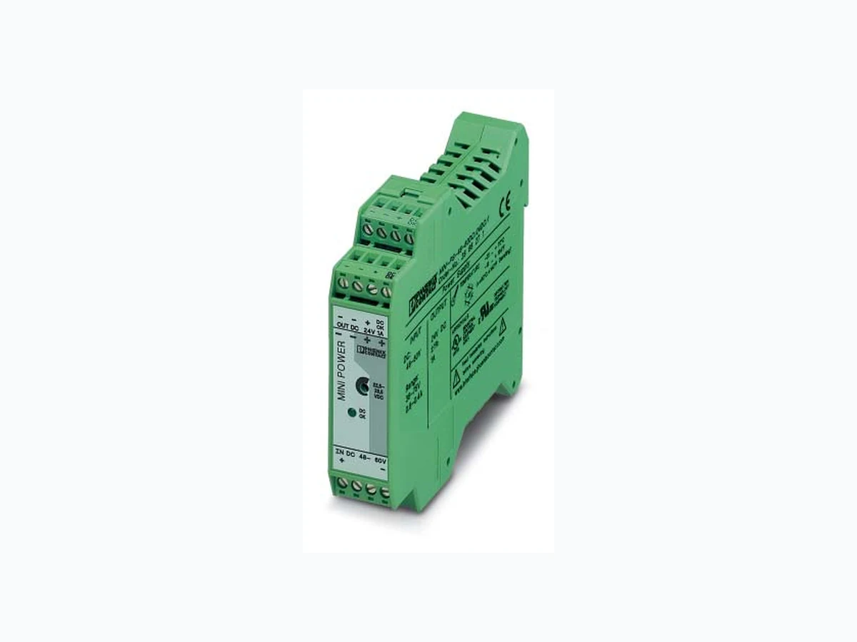
102053 PHOENIX
Document overview
- Manufacturer or author: Provided By digicamel.com
- PDF pages: 8
Technical content
design with widths of 22.5 mm, Global use due to a wide-range input A high level of operational safety in complex global networks Reliable startup of heavy loads due to POWER BOOST The reliability of a power supply unit determines the availability of individual components in a system and whether complex systems can function safely. The globalization of markets increases the demands placed on the power supply unit. A wide-range input and a high level of availability are required. These requirements are met by MINI POWER. 1. Short Description MINI POWER is the extra narrow power supply unit, which is available in widths of 22.5 mm, 45 mm, and In addition to a 24 V version with output currents of
1 A , 2 A, and 4 A, special voltages are also available
with 5 V/3 A, +/-15 V/1 A, and 10 - 15 V/2 A for connection to single-phase AC networks or to two external conductors in three-phase networks with nominal voltages of 100 - 240 V AC. Two DC/DC converters convert low direct voltages into an adjustable and regulated 24 V output voltage. With the DIN rail bus connector, the MINI-SYS-PS can be connected in parallel to supply other modules in the same system with a regulated 24 V DC voltage. Reliable startup of heavy loads is ensured by a power reserve of up to 100% – the POWER BOOST. The high level of operational safety is also ensured in complex global networks. MINI POWER also operates in applications where static voltage dips, transient power supply failures or phase failure are common. Powerful capacitors ensure mains buffering of more than 20 ms at full load. 2. Area of Application MINI POWER can be used globally due to the consistent provision of a wide-range input. In this way, your entire system can be tested at any production location in the world and can be delivered to any location in the world without faulty switching of the input voltage. This reduces storage costs and logistical effort. An international approval package including UL 60950 for IT equipment and UL 508 for industrial control equipment enables the device to be used globally. Power Supply Unit, Primary Switched, Narrow Design MINI-PS-48-60DC/24DC/1 Headquarters: © Phoenix Contact GmbH & Co. KG • Flachsmarktstraße 8 • 32825 Blomberg • Germany Phone +49 - 52 35 - 30 0 • Fax +49 - 52 35 - 34 12 00 • www.phoenixcontact.com Local Contact: www.phoenixcontact.com/salesnetwork
PHOENIX CONTACT page 2 of 8 Solid Stranded Torque [mm ]A WG [Nm] [Ib in]
Description
primary switched, narrow design Technical Data Input Data Nominal input voltage Input voltage range (current consumption) Current consumption (for nominal values) Inrush current limiting Mains buffering for a nominal load (typical) Switch-on time after applying the mains voltage Transient surge protection Input fuse, internal Output Data Nominal output voltage U N /tolerance Setting range for the output voltage Output current during convection cooling and nominal values POWER BOOST I BOOST (typical t < 2 min., -25°C to 60°C [-13°F to +140°F]) Nominal output current I N -25°C to +60°C (-13°F to +140°F) Derating Short-circuit current limit Startup of capacitive loads System deviation on: Static load change 10 - 90% Dynamic load change 10 - 90% Input voltage change ±10% Maximum power dissipation No load/nominal load Level of efficiency (typical) Response time U OUT (10% - 90%) Residual ripple/switching peaks (20 MHz) Can be connected in parallel Internal surge protection Resistance to return supply Signal Output Data DC OK (active) (U out > 21.5 V DC high signal) LED (U out > 21.5 V DC LED permanently on) MINI-PS-48-60DC/24DC/1 DC/DC Converter U u Type Order No. Pcs. Pkt. MINI-PS-48-60DC/24DC/1 28 66 27 1 48 - 60 V DC (wide-range input) 36 - 75 V DC 0.6 (at 48 V DC), 0.5 (at 60 V DC) < 15 A, typical 15 ms (at 48 V DC), 20 ms (device protection) (at 60 V DC) < 0.5 s Varistor T 3.15 AL 250 V (3.15 A)
24 V DC/±1%
22.5 - 28.5 V DC
1.5 A (U
= 24 V)
1 A (U
= 24 V) From +60°C (+140°F), 2.5% per Kelvin 6 A Unlimited < 1%, typical < 3%, typical < 0.1%, typical
1.2 W/5 W
85% (at 60 V DC and at nominal values) < 30 ms, typical < 100 mV pp (for nominal values) To increase redundancy and power Yes, limited to 35 V DC, approximately
35 V DC
+24 V signal/20 mA, maximum Green LED 99 mm (3.898 in.) 22.5 mm (0.886 in.) 114.5 mm (4.508 in.) /G4E /G43 /G4E /G43 /G44 /G43 /G20 /G4F /G4B Power Supply Unit, Primary Switched, Narrow Design – MINI-PS-48-60DC/24DC/1 3. Technical Data 7 mm (0.28 in.)
PHOENIX CONTACT page 3 of 8 Power Supply Unit, Primary Switched, Narrow Design – MINI-PS-48-60DC/24DC/1 General Data Insulation voltage: Input/output Approval package Electrical equipment of machines Safety transformers for switched-mode power supply units Electrical safety (of IT equipment) Industrial control equipment Electronic equipment for use in electrical power installations Safety extra-low voltage Safe isolation Protection against electric shock, basic requirements for safe isolation in electrical equipment Limitation of harmonic line currents Mounting position Can be mounted with spacing - Vertically - Horizontally Degree of protection Class of protection MTBF Housing version Weight Dimensions (W x H x D) Climatic Data Ambient temperature Operation Storage Humidity Vibration According to IEC 68-2-6 Shock According to IEC 68-2-27 Pollution degree Climatic category cccc Conformance With EMC Directive 89/336/EEC and Low Voltage Directive 73/23/EEC EMC (Electromagnetic Compatibility) Noise Immunity According to EN 61000-6-2: Electrostatic discharge (ESD) EN 61000-4-2 Housing Contact discharge: Air discharge: Electromagnetic HF field EN 61000-4-3 Housing Frequency: Field strength: Fast transients (burst) EN 61000-4-4 Input: Output: Signal: Surge current loads (surge) EN 61000-4-5 Conducted interference EN 61000-4-6 I/O/S: Frequency: U Voltage dips EN 61000-4-11 Input: Noise Emission According to EN 50081-2: Radio interference voltage EN 55011 Radio interference emission EN 55011 EN 55011 corresponds to CISPR11/EN 55022 corresponds to CISPR22 EN 61000 corresponds to IEC 1000 Criterion A: Normal operating characteristics within the speci fied limits. Criterion B: Temporary adverse effects on the operating characteristics, which the device corrects automatically. 1.5 kV AC (type test)/1 kV AC (routine test) EN 60 204 (Surge Voltage Category III) EN 61 558-2-17 EN 60950/VDE 0805 UL/C-UL Recognized UL 60 950 u UL/C-UL Listed UL 508 EN 50 178/VDE 0160 PELV (EN 60 204) SELV (EN 60 950) VDE 0100-410 DIN VDE 0106-101 According to EN 61000-3-2 On horizontal NS 35 DIN rail according to EN 60715 With spacing of 5 cm (1.969 in.) 0 cm (0 in.) IP20 ΙΙ , (in closed control cabinets) > 500,000 h according to IEC 1709 (SN 29 500) Polyamide PA, color green 0.2 kg, approximately -25°C to +70°C [-13°F to +158°F] (> +60°C [140°F] derating) -40°C to +85°C [-40°F to +185°F] Up to 95% at +25°C [77°F], no condensation < 15 Hz, amplitude ±2.5 mm/15 Hz - 150 Hz, 2.3 g 30 g all space directions 2 (according to EN 50 178) 3K3 (according to EN 60 721) Requirements EN 61 000-6-2 MINI-PS-48-60DC/24DC/1 4 kV 8 kV > Level 3 8 kV 8 kV 80 - 1000 MHz
10 V/m
2 kV (Level 3) 2 kV (Level 3) 1 kV (Level 2) 2 kV asymmetrical 1 kV symmetrical 4 kV (Level 3) 2 kV (Level 3) asymmetrical 0.15 - 80 MHz 10 V Level 3 0.15 - 80 MHz 10 V 30% reduction of the input voltage for 0.5 periods See Input Data: Mains buffering > 20 ms Class A EN 55011 (EN 55022) Class B Class A EN 55011 (EN 55022) Class B symmetrical: Cable to cable asymmetrical: Cable to ground Class A: Industrial applications Class B: Industrial and domestic applications U LISTED
PHOENIX CONTACT page 4 of 8 1111 DC input: 36 - 75 V DC input voltage (0.2 mm to 2.5 mm solid) (0.2 mm to 2.5 mm stranded) (25 - 14 AWG) Internal fuse 3.15 A 2222 DC output:
24 V DC output voltage (default),
can be set from 22.5 - 28.5 V DC using potentiometer (0.2 mm to 2.5 mm solid) (0.2 mm to 2.5 mm stranded) (25 - 14 AWG) The device is idling-proof and short-circuit-proof. 3333 DC OK output active 4444 Potentiometer 22.5 - 28.5 V DC 5555 DC OK LED 6666 Universal latching foot for EN DIN rails 5 6 7 8 + NC NC – MINI-PS-48-60DC/24DC/1Order No.: 28 66 2 7 1 U INDUSTRIALCONTROL EQUIPMENT 43KA LISTED APPROV ALS u INFORMATION TECHNOLOGY EQUIPMENT Power Supply INPUT OUTPUT DC: 48-60V Range: 36-75V0.8-0.4A 24V DC ±1%1A Read installation instructions before connecting to mains www.interface.phoenixcontact.com TEMPERA TURE - 25 … + - 13 … + 154 (>+60 °C/+140 °F Derating) –25 MINI POWER DC OK NC NC DCOK IN DC 48 - 60 V OUT DC 24V 1 A 22.5-28.5VDC Figure 04 Power Supply Unit, Primary Switched, Narrow Design – MINI-PS-48-60DC/24DC/1 4. Device View, Connections, and Control Elements 5. Safety Notes and Warning Instructions To ensure that the device can be operated safely and all functions can be used, please read these instructions carefully. Installation and startup must only be carried out by qualified personnel. The relevant country-specific regulations (e.g., VDE, DIN) must also be observed. Before startup it is particularly important to ensure that:
- All supply lines have sufficient fuse protection and are the correct size.
- All output cables are the correct size for the maximum device output current or have separate fuse protection.
- Sufficient convection is ensured.
PHOENIX CONTACT page 6 of 8 Power Supply Unit, Primary Switched, Narrow Design – MINI-PS-48-60DC/24DC/1
6.2 Connecting Cable
The device is equipped with COMBICON connectors. This reliable user-friendly connection method enables quick device connection and visible isolation of the electrical connection, if required. Only operate connectors when the power is switched off. The following cable cross sections can be connected: For reliable and safe-to-touch connections: Strip 7 mm (0.28 in.) from the connector ends. 6.3. Input ( 1111 , Figure 9) The 48 - 60 V DC connection is made using the "+" and "-" screw connections. Solid [mm Stranded [mm AWGT orque [Nm] [Ib in] 1111 2222 3333 7 mm (0.28 in.) 5 6 7 8 + NC NC – MINI-PS-48-60DC/24D Order No.: 28 66 2 7 1 U APPR O Power Supply INPUT OUTPUT DC: 48-60VRange: 36-75V0.8-0.4A 24V DC ±1%1A TEM P MINI POWER DC OK NC NC DCOK IN DC 48 - 60 V OUT DC 24V 1 A 22.5-28.5VDC 22224444 1111 3333 Figure 09 Protecting the Primary Side The device must be installed according to the specifications of EN 60 950. Device protection is not required, as an internal fuse is present. If the internal fuse is blown, this is most probably due to a device fault. In this case, the device should be checked in the factory.
PHOENIX CONTACT page 7 of 8 Power Supply Unit, Primary Switched, Narrow Design – MINI-PS-48-60DC/24DC/1 DC OK24 V DC 20 mA + – – Output 24V DC DC OK Figure 10 IBOOST UOUT [V] IOUT [A]IN UN 36 W 1 1.5 Figure 11 < 60°C (140°F) UOUT = 24 V t < 2 min. The U/I characteristic curve ensures that both heavy capacitive loads and devices with DC/DC converters can be supplied by MINI POWER in the input circuit without any problems. Connected fuses are reliably tripped. The selectivity in your system configuration is ensured at all times. 6.4. Output ( 2222 , Figure 9) The 24 V DC connection is made using the "+" and "-" screw connections on the screw connection 2222 . The output voltage set upon delivery is 24 V DC. The output voltage can be adjusted from 22.5 to
28.5 V DC on the potentiometer
Protecting the Secondary Side: The device is electronically short-circuit-proof and idling-proof. In the event of an error, the output voltage is limited to a maximum of 35 V DC. It should be ensured that all output cables are the correct size for the maximum output current or have separate fuse protection. The cable cross sections in the secondary circuit should be large enough to keep the voltage drops on the cables as low as possible. Active Signal Output ( 3333 , Figure 10) The 24 V DC signal is between the "DC OK" and "-" connection terminal blocks and can be loaded with 20 mA maximum. This signal output indicates that the output voltage has fallen below 21.5 V DC when "active high" changes to "low". The DC OK signal is isolated from the power output. This ensures that a separate supply does not enter from devices connected in parallel. The 24 V DC signal can be connected directly to a logic input for evaluation. Signaling The active DC OK switching output and the DC OK LED provide function monitoring. 7. Installation 7.1. Output Characteristic Curve The device can supply a nominal output current of 1 A up to an ambient temperature of 60°C (140°F). At temperatures up to 60°C (140°F), the POWER BOOST provides a short-term output current of 1.5 A for a few minutes. In the event of heavier loads the working point demonstrates the U/I characteristic curve shown in Figure 11. On an overload or short circuit, the entire output current I BOOST is provided permanently at a reduced output voltage. Once the overload or short circuit has been removed, the entire set secondary voltage is available again. Status 1 Status 2 Green "DC OK" LED 5555 ON OFF Active DC OK switching output 3333 U = +24 V (with reference to "-") U = 0 V (with reference to "-") Meaning Normal operation of the power supply unit U OUT > 21.5 V UOUT ≤ 21.5 V DC
- Secondary load short circuit or overload
- No mains voltage or device fault
PHOENIX CONTACT page 8 of 8 7.2. Temperature Response The device can supply a nominal output current of 1 A up to an ambient temperature of 60°C (140°F). At temperatures up to 60°C (140°F), the POWER BOOST provides a short-term output current of 1.5 A for a few minutes. The output power must be decreased by 2.5% per Kelvin temperature increase for ambient temperatures above +60°C (140°F). At ambient temperatures above +70°C (+158°F) or in the event of a thermal overload, the device reduces the output power to protect itself and returns to normal operation once it has cooled down. 7.3. Parallel Operation Devices of the same type can be connected in parallel to increase both redundancy and power. The default setting does not have to be adjusted. If the output voltage is adjusted, an even current distribution can be ensured by precisely setting all power supply units that are operated in parallel to the same output voltage. To ensure symmetrical current distribution we recommend that all cable connections from the power supply unit to the DIN rail are the same length and have the same cross section. Depending on the system, for parallel connection of more than two power supply units a protective circuit should be installed at each individual device output (e.g., decoupling diode or DC fuse). This prevents high return currents in the event of a secondary device fault. 7.4. Redundancy Operation Redundant connections are designed for supplying systems, which place particularly high requirements on operational safety. If a fault occurs in the primary circuit of the first power supply unit, the second device automatically takes over the complete power supply without interruption, and vice versa. For this purpose, the power supply units to be connected in parallel must be large enough that the total current requirements of all loads can be fully met by one power supply unit. External decoupling diodes are required for 100% redundancy. 7.5. Increasing Power The output current can be increased to n x I N where n is the number of devices connected in parallel. Parallel connection for increasing power is used when extending existing systems. A parallel connection is recommended if the power supply unit does not cover the current consumption of the most powerful load. Otherwise, the loads should be divided over independent individual devices. A maximum of five devices can be connected in parallel. Power Supply Unit, Primary Switched, Narrow Design – MINI-PS-48-60DC/24DC/1 0 40 60200 40 6020 Output current [A] UOUT = 24 V Ambient temperature [°C] Figure 12 1.0 + – + – Σ = 1 A MINI
24 V/1 A
+ – + – Σ = 2 A MINI ∀ PHOENIX CONTACT 11/15/03 TNR:102053-00 http://www.phoenixcontact.com