
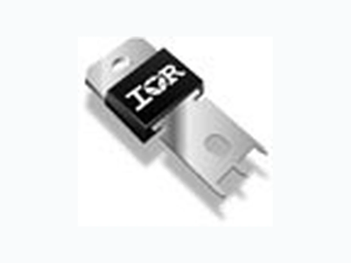
100BGQ045 IRF
Document overview
- Manufacturer or author: Provided By digicamel.com
- PDF pages: 7
Technical content
IF(AV) Rectangular waveform 100 A @ TC 100 °C IDC Maximum 141 A VRRM 45 V IFSM @ tp = 5 µs sine 4400 A V F @ 100 Apktypical 0.63 V @ TJ 150 °C TJ range - 55 to 150 °C SCHOTTKY RECTIFIER 100 Amp 100BGQ045 100BGQ045J PD-20709 rev. C 11/99 www.irf.com Characteristics 100BGQ045 Units The NEW 100BGQ045 Schottky rectifier has been optimized for ultra low forward voltage drop specifically for low voltage output in high current AC/DC power supplies. The proprietary barrier technology allows for reliable operation up to 150°C junction temperature. Typical applications are in switching power supplies, converters, reverse battery protection, and redundant power subsystems. 150°C T J operation High Frequency Operation Ultra low forward voltage drop Continuous High Current operation Guard ring for enhanced ruggedness and long term reliability PowIRtabTM package Major Ratings and Characteristics Description/Features Case Styles 100BGQ045 100BGQ045J
100BGQ045, 100BGQ045J PD-20709 rev. C 11/99 www.irf.com2 Voltage Ratings VFM Forward Voltage Drop (1) (2)0.52 0.56 V @ 50A 0.67 0.73 V @ 100A 0.47 0.52 V @ 50A 0.63 0.68 V @ 100A I RM Reverse Leakage Current (1) 0.3 1 mA T J = 25 °C 180 320 mA T J = 125°C 600 1000 mA T J = 150 °C V R = 45 V VF(TO) Threshold Voltage 0.379 VT J = TJ max. rt Forward Slope Resistance 2.7 m Ω CT Max. Junction Capacitance 2700 pF V R = 5VDC , (test signal range 100Khz to 1Mhz) 25 °C LS Typical Series Inductance 3.5 nH Measured from tab to mounting plane dv/dt Max. Voltage Rate of Change 10,000V/ µs (Rated VR) TJ Max. Junction Temperature Range -55 to 150 °C Tstg Max. Storage Temperature Range -55 to 150 °C R thJC Max. Thermal Resistance Junction0.50 °C/W DC operation to Case RthCS Typical Thermal Resistance, Case to0.20 °C/W Mounting surface , smooth and greased Heatsink wt Approximate Weight 5 (0.18) g (oz.) T Mounting Torque Min. 1.2 (10) Max. 2.4 (20) Case Style PowIRtabTM N*m (Ibf-in) Thermal-Mechanical Specifications Parameters 100BGQ Units Conditions IF(AV) Max. Average Forward Current 100 A 50% duty cycle @ TC = 100°C, rectangular wave form IF(RMS) RMS Forward Current 141 A T C = 95°C IFSM Max. Peak One Cycle Non-Repetitive4400 5µs Sine or 3µs Rect. pulse Surge Current 830 10ms Sine or 6ms Rect. pulse EAS Non-Repetitive Avalanche Energy 40 mJ T J = 25 °C, IAS = 6 Amps, L = 2.0 mH IAR Repetitive Avalanche Current 6 A Current decaying linearly to zero in 1 µsec Frequency limited by TJ max. VA = 1.5 x VR typical Parameters 100BGQ Units Conditions Absolute Maximum Ratings A Following any rated load condition and with rated V RRM applied TJ = 25 °C TJ = 150 °C VR = rated VR Electrical Specifications Parameters 100BGQ Units Conditions Typ. Max. (1) Pulse Width < 300µs, Duty Cycle < 2% (2) VFM = VF(TO) + rt x IF Part number 100BGQ045 VR Max. DC Reverse Voltage (V) VRWM Max. Working Peak Reverse Voltage (V) 45
100BGQ045, 100BGQ045J PD-20709 rev. C 11/99 www.irf.com Fig. 2 - Typical Values of Reverse Current Vs. Reverse Voltage Fig. 3 - Typical Junction Capacitance Vs. Reverse Voltage Fig. 4 - Maximum Thermal Impedance ZthJC Characteristics Fig. 1 - Maximum Forward Voltage Drop Characteristics 100 1000 F FM T = 150°C T = 125°C T = 25°C J J J Forw ard Voltage D rop - V (V) In stan tane ous Fo rw ard C urre nt - I (A ) 0.01 0.1 100 1000 0 5 10 15 20 25 30 35 40 45 R R 125°C 100°C 75°C 50°C 25°C Rev erse C urre nt - I (m A ) T = 150°CJ Reverse Voltage - V (V) 0.01 0.1 thJC t , Rectangular Pulse Duration (Seconds) Single Pulse (Therm al Resistance) T herm al Im pedan ce Z (°C /W ) Notes : 1. Duty factor D = t / t 2. Peak T = P x Z + T 1 2 J thJ C CDM D = 0.75 D = 0.50 D = 0.33 D = 0.25 D = 0.20 2t PDM 100 1000 10000 0 1 02 03 04 05 0 R TJun ction C apacita nc e - C (pF) T = 25°CJ Rever s e Vol t age - V ( V)
100BGQ045, 100BGQ045J PD-20709 rev. C 11/99 www.irf.com4 Fig. 8 - Unclamped Inductive Test Circuit Fig. 5 - Maximum Allowable Case Temperature Vs. Average Forward Current Fig. 6 - Forward Power Loss Characteristics Fig. 7 - Maximum Non-Repetitive Surge Current (3)Formula used: TC = TJ - (Pd + PdREV ) x RthJC ; Pd = Forward Power Loss = IF(AV) x VFM @ (IF(AV) / D) (see Fig. 6); Pd REV = Inverse Power Loss = VR1 x IR (1 - D); IR @ VR1 = 80% rated VR 100 1000 10000 10 100 1000 10000 FSMN on -Repetitive Surg e Curren t - I (A) p At Any Rated Load Condi t i on A nd W ith Rated V Applied Follo w ing Surge RRM Square W ave Pulse D uration - t (m icro se c) 100 120 0 20 40 60 80 100 120 140 160 DC Av erage Po w e r Lo ss - (W atts) F(AV) RMS Li m i t D = 0. 20 D = 0. 25 D = 0. 33 D = 0. 50 D = 0. 75 Average Forw ard Current - I (A ) 100 110 120 130 140 150 0 20 40 60 80 100 120 140 160 DC Al l owabl e Cas e Temper atur e - (° C) F(AV)A verage Forw ard C urren t - I (A ) see note ( 3) Square wave (D = 0.50) 80% Rated V appl iedR FREE-W HEEL D I O D E 40HFL40S02C URRENT MO NI T O R HI GH-SPEED SW ITC H IRFP460 L DUT Rg = 25 ohm Vd = 25 Vo l t+
100BGQ045, 100BGQ045J PD-20709 rev. C 11/99 www.irf.com Outline Table Case Style PowIRtabTM Dimensions in millimeters and (inches) Ordering Information Table Device Code 1 24 3 1 - Current Rating 2 - Essential Part Number 3 - Voltage code: Code = VRRM 4 - none = PowIRtabTM standard
6 J = Short Lead Version
100 BGQ 045 J
100BGQ045, 100BGQ045J PD-20709 rev. C 11/99 www.irf.com6 Outline T able Case Style PowIRtabTM "J" version Dimensions in millimeters and (inches)
100BGQ045, 100BGQ045J PD-20709 rev. C 11/99 www.irf.com EUROPEAN HEADQUARTERS: Hurst Green, Oxted, Surrey RH8 9BB, U.K. Tel: ++ 44 1883 732020. Fax: ++ 44 1883 733408. IR CANADA: 15 Lincoln Court, Brampton, Markham, Ontario L6T3Z2. Tel: (905) 453 2200. Fax: (905) 475 8801. IR GERMANY: Saalburgstrasse 157, 61350 Bad Homburg. Tel: ++ 49 6172 96590. Fax: ++ 49 6172 965933. IR ITALY:Via Liguria 49, 10071 Borgaro, Torino. Tel: ++ 39 11 4510111. Fax: ++ 39 11 4510220. IR FAR EAST:K&H Bldg., 2F, 30-4 Nishi-Ikebukuro 3-Chome, Toshima-Ku, Tokyo, Japan 171. Tel: 81 3 3983 0086. IR SOUTHEAST ASIA: 1 Kim Seng Promenade, Great World City West Tower,13-11, Singapore 237994. Tel: ++ 65 838 4630. http://www.irf.com Fax-On-Demand: +44 1883 733420 Data and specifications subject to change without notice. This model This model has been developed by Wizard SPICE MODEL GENERATOR (1999) ( International Rectifier Corporation ) contains Proprietary Information SPICE Model Diode is composed by a simple diode plus paralled VCG2T .SUBCKT 100bgq45 ANO CAT D1 ANO 1 DMOD (0.24359) *Define diode model . MODEL DMOD D ( IS=6.61799286342482E-05A, N=1.0212796726385, BV=45V, + IBV=0.115140026620575A,RS= 0.0005748724,CJO=3.31930927290723E-08, +VJ=0.456112448442971,XTI=2, EG=0.721992455742664) * Implementation of VCG2T VX 1 2 DC 0V R1 2 CAT TRES 1E-6 .MODEL TRES RES (R=1, TC1=9.83346387011944) GP1 ANO CAT VALUE= {-ABS (I(VX)) *(EXP((((-2.949174E-03/ 9.833464)*((V(2,CAT)*1E6) / (I(VX)+1E-6)-1))+1)*6.600191E-2*ABS(V(ANO,CAT)))-1)} .ENDS 100bgq45 Thermal Model Subcircuit .SUBCKT 100bgq45T 5 1 CTHERM1 5 4 1.66E+3 CTHERM2 4 3 2.22E+2 CTHERM3 3 2 1.48E+5 CTHERM4 2 1 3.12E+5 RTHERM1 5 4 3.42E-2 RTHERM2 4 3 2.55E-1 RTHERM3 3 2 8.41E-2 RTHERM4 2 1 1.81E-4 .ENDS 100bgq45T