

 Download PDF
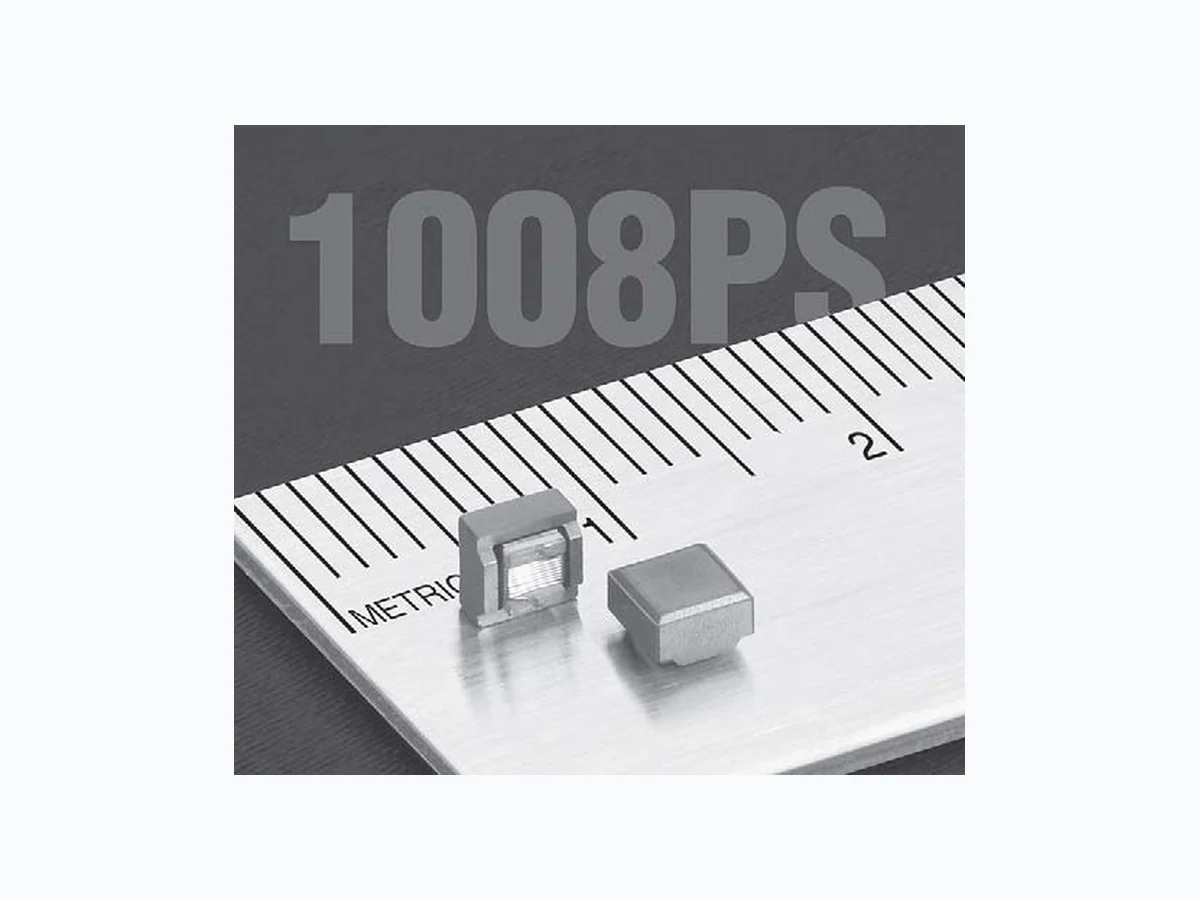
1008PS COILCRAFT
Document overview
- Manufacturer or author: Provided By digicamel.com
- PDF pages: 2
Technical content
© Coilcraft, Inc. 2009 Specifications subject to change without notice. Please check our website for latest information. Power Chip Inductors – 1008PS Series Document 219-1 Document 219-1 Revised 08/17/09 Inductance DCR 4 SRF5 Isat (A)6 Irms (A)7 Part ±10%2 Q max typ 10% 20% 30% 20°C 40°C number1 (µH) min 3 (Ohms) (MHz) drop drop drop rise rise
- Shielded power chip inductors Excellent current handling for a part this size 1. When ordering, specify termination and packaging codes: 1008PS-105KLC Termination: L= RoHS compliant silver-palladium- platinum-glass frit. Special order: T = RoHS tin-silver-copper (95.5/4/0.5) or S = non-RoHS tin-lead (63/37). Packaging: C =7 ″ machine-ready reel. EIA-481 embossed plastic tape (750 parts per full reel). B= Less than full reel. In tape, but not machine ready. To have a leader and trailer added ($25 charge), use code letter C instead. D=1 3″ machine-ready reel. EIA-481 embossed plastic tape. Factory order only, not stocked (2500 parts per full reel). 2. Inductance measured at 100 kHz, 0.1 Vrms, using Coilcraft SMD-A fixture in Agilent/HP 4263B impedance analyzer or equivalent. 3. Q measured at 1 MHz using an Agilent/HP 16193 test fixture and an Agilent/HP 4291 or equivalent. 4. DCR measured on micro-ohmmeter and Coilcraft CCF840 test fixture. 5. SRF measured using a Coilcraft SMD-D test fixture and an Agilent/HP 8753D network analyzer or equivalent. 6. DC current at which the inductance drops the specicfied amount from its value without current. 7. Current that causes the specified temperature rise from 25°C ambient. 8. Electrical specifications at 25°C. Refer to Doc 362 “Soldering Surface Mount Components” before soldering. For new designs, we recommend the LPS4018 as an alternative to this series. The LPS4018 series offers a significantly lower profile and much lower DCR. We will continue to manufacture and support the 1008PS.
© Coilcraft, Inc. 2009 Specifications subject to change without notice. Please check our website for latest information. Document 219-2 Power Chip Inductors – 1008PS Series Typical L vs Frequency Typical L vs Current 0.01 0.1 11 0 0.1 100 1000 10000 Inductance (µH) Frequency (MHz) 1000 µH 100 µH 10 µH 1µ H 0.01 0.1 11 0 Current (A) 0.1 100 1000 10000 Inductance (µH) 100 µH 10 µH 1µ H 1000 µH ABCDEF G max max max max max max typ H I J 3,81 3,78 2,74 1,78 2,59 2,13 0,51 2,54 1,02 1,27 mm A B FD C E G I I J H Recommended Land Pattern Terminal wraparound: approx 0.015/0,38 both ends Document 219-2 Revised 08/17/09 Irms Derating -40 -20 0 20 40 60 80 100 160 140120 Ambient temperature (°C) Percent of rated rms I 120 110 100 25°C Core material Ceramic/Ferrite Core and winding loss See www.coilcraft.com/coreloss Terminations RoHS compliant silver-palladium-platinum-glass frit. Other terminations available at additional cost. Weight 122 – 132 mg Ambient temperature –40°C to +105°C with Irms current, +105°C to +145°C with derated current Storage temperature Component: –40°C to +145°C. Packaging: –40°C to +80°C Resistance to soldering heat Max three 40 second reflows at +260°C, parts cooled to room temperature between cycles Temperature Coefficient of Inductance (TCL)+100 to +350 ppm/°C Moisture Sensitivity Level (MSL) 1 (unlimited floor life at <30°C / 85% relative humidity) Failures in Time (FIT) / Mean Time Between Failures (MTBF) 38 per billion hours / 26,315,789 hours, calculated per Telcordia SR-332 Packaging 750/7″reel; 2500/13″ reel Plastic tape: 12 mm wide, 0.3 mm thick, 8 mm pocket spacing, 3.3 mm pocket depth PCB washing Only pure water or alcohol recommended