
DATASHEET SEARCH SITE
Document overview
- Manufacturer or author: Provided By digicamel.com
- PDF pages: 7
Technical content
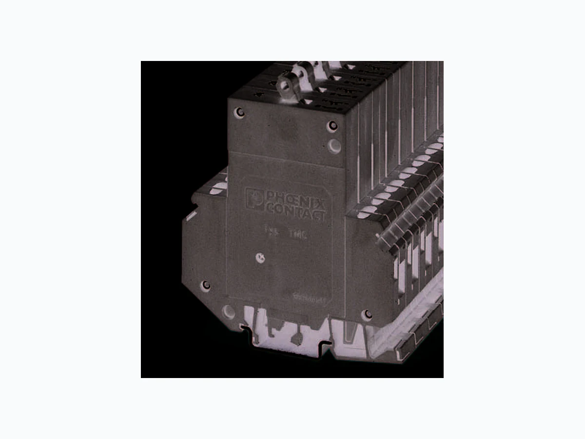
100695_en_03 TMC Data sheet © PHOENIX CONTACT 2012-03-09 1D e s c r i p t i o n Single or multi-position thermomagnetic circuit breaker with lever actuation, DIN rail mounting, trip-free mechanism that cannot be influenced, various characteristic curves, all-pole tripping. The circuit breakers meet the requirements of circuit breaker standard EN 60934 (IEC 60934): S-type, TM. Typical areas of application are telecommunications systems, power supply units, industrial switchgear and control systems, and rail vehicles. The ideal characteristic curve shown here illustrates the curve of the thermomagnetic trigger characteristic. The time- delayed tripping protects the thermal part of the characteristic curve against overload. The magnetic part of the circuit breaker responds without delay to high overload and short-circuit currents and trips within a few milliseconds. Figure 1 Ideal characteristic curve ① Thermal tripping range ② Magnetic tripping range 0,01 0,1 100 2 4 6 810 20 Multiples of the nominal current t [s] ① ② Make sure you always use the latest documentation. It can be downloaded at www.phoenixcontact.net/catalog. This data sheet is valid for all products listed on the following page: Thermomagnetic circuit breaker for mounting on a DIN rail
100695_en_03 PHOENIX CONTACT 2 2O r d e r i n g d a t a
2.1 Order key
TMC with 1-pos. main current path, one N/O contact, medium-blow characteristic curve, and a nominal current of
2 A: TMC 1 M1 100 2A
3 Technical data
Thermomagnetic circuit breaker Description Type Order No. Pcs./Pkt. Thermomagnetic circuit breaker, with universal foot for mounting on 3 or 4 TMC... (see order key) 6 Accessories Description Type Order No. Pcs./Pkt. Insertion bridge, insulated, 80-pos. (Imax: 50 A) (For central supply IN: 80 A) EB 80-12 3009338 1 Zack marker strip, 10-section, for labeling the center of the terminal block ZB 6 See CLIPLINE catalog UniCard sheets, for labeling terminal blocks using a Zack marker strip groove, 96-section, can be labeled with BLUEMARK and CMS-P1-PLOTTER, color: white UC-TM 5 0818108 10 Screwdriver SZS 0,6X3,5 1205053 10 Type Main current paths Characteristic curves Auxiliary contact versions Nominal current TMC 1 Single-pos. 2 Two-pos. 3 Three-pos. magnetic 2 x IN ... 4 x IN DC (fast-blow), only for DC applications M1 Thermal 1.05 - 1.4 IN, magnetic 6 x I N ... 12 x IN AC, (medium-blow) 100 Single-pos.: 1 N/O contact 200 Single-pos.: 1 N/C contact 120 Two-pos.: 1 N/O contact, 1 N/C contact 122 Three-pos.: 1 N/O contact, 2 N/C contacts 0.2 A 2.5 A
0.3 A 3 A
0.4 A 4 A
0.5 A 5 A
0.6 A 6 A
0.8 A 8 A
1 A 10 A
1.2 A 12 A
Nominal voltage 250 V AC (65 V DC), 3 433 V AC (50/60 Hz) Nominal current range 0.2 A ... 16 A, see order key Auxiliary circuit 240 V AC (65 V DC), 1 A Service life 10,000 cycles with 1 x IN, inductive Ambient temperature -30°C ... +60°C (T 60) Insulation coordination (IEC 60664) 2.5 kV/2, increased insulation in the actuation area Dielectric strength Actuation area Main to auxiliary circuit Position to position
3000 V AC test voltage
1500 V AC test voltage
Insulation resistance > 100 M (500 V DC)
100695_en_03 PHOENIX CONTACT 3 Switching capacity Icn Characteristic curve F1 and M1 400 A 800 A
2500 A (at 32 V DC)
Switching capacity IN (UL 1077) 1 and 2-pos. 3-pos. 1 and 2-pos.
277 V AC/5000 A
480 V AC/5000 A
65 V DC/2000 A
Degree of protection (IEC 60529) Actuation area Connection area IP30 IP20 Vibration resistance Characteristic curve F1 Characteristic curve M1 Test according to IEC 60068-2-6, Test Fc, 10 frequency cycles/axis Shock resistance Characteristic curve F1 Characteristic curve M1 25g (11 ms), shock direction 1, 2, 3, 4, 5; 10g (11 ms), shock direction 6 25g (11 ms), shock direction 1, 2, 3, 4, 5; 20g (11 ms), shock direction 6 Test according to IEC 60068-2-27, Test Ea Corrosion resistance 96 hours in 5% salt fog Test according to IE 60068-2-11, Text Ka Humidity test 240 hours in 95% relative humidity Test according to IE 60068-2-78, Text Cab Weight 60 g per position, approximately Technical data Technical data according to IEC/DIN VDE Impulse voltage withstand level 4 kV Pollution degree 3 Auxiliary contact: maximum load current 1 A for 2.5 mm 2 Maximum cross-section with insertion bridge (solid and stranded) 1.5 mm2 Surge voltage category III Insulation material group I Connection capacity Main contact Auxiliary contact Connection capacity Solid Stranded 0.2 mm2 ... 6 mm2 0.2 mm2 ... 4 mm2 Connection capacity (stranded with ferrule) Without plastic sleeve With plastic sleeve 0.25 mm2 ... 4 mm2 Two conductors with the same cross-section Solid and stranded Stranded with ferrule without plastic sleeve Stranded with TWIN ferrule with plastic sleeve 0.2 mm 2 ... 1 mm2 0.2 mm2 ... 1 mm2
100695_en_03 PHOENIX CONTACT 5 Figure 4 Dimensional draw ing (dimensions in mm) Groove for marking labels Main contact Connection terminal block M3, maximum of 6 mm² (solid), 0.5 Nm tightening torque Auxiliary contact Connection terminal block M3, maximum of 1.5 mm² (solid),
0.5 Nm tightening torque
100695_en_03 PHOENIX CONTACT 6 4B a c k u p f u s e The table lists the maximum switching current, the relevant internal resistance, and the resulting backup fuse.
5 Trigger characteristics
The thermomagnetic circuit breaker is available in 18 nominal current levels and in single and multi-pos. versions. The version with the "medium-blow (M1)" trigger characteristic is suitable for AC and DC applications. The "fast-blow (F1)" characteristic version is suitable for DC applications. The characteristic curves (see page 7) depend on the ambient temperatures. To avoid early or late disconnection, the circuit breaker nominal current must be multiplied by a factor. The characteristic curves (see page 7) are also valid for multi-position devices if all positions have an equal load. For multi-position devices and only 1-pos. overload, the thermal tripping limit changes for characteristic curves F1 and M1 to a maximum of 1.7 x IN. For DC, the magnetic operate values of the curves are around factor 1.3 higher. Tripping is supported even with high-energy current peaks < 0.003 s. In this case, the nominal current can only be led to 80%. Alternatively, the load current can be increased by a multiplication factor and the circuit breaker dimensioned accordingly. NOTE: Use a backup fuse in combination with the circuit breaker if the maximum switching current can be exceeded in the event of an error. Nominal current NH backup fuse Internal resistance Switching capacity according to EN 60934 F1 (fast- blow) for DC (medium- blow) for DC/AC 0.2 A Any 39.3 26.1 400 A 0.3 A Any 17.5 11.6 400 A 0.4 A Any 9.2 6.6 400 A 0.5 A Any 6.8 4.1 400 A 0.6 A Any 4.2 3 400 A 0.8 A Any 2.8 1.65 400 A 1 A Any 1.6 1.10 400 A 1.5 A 25 A 0.78 0.47 400 A 2 A 25 A 0.42 0.28 400 A 2.5 A 25 A 0.26 0.183 400 A 3 A 25 A 0.18 0.124 400 A 4 A 25 A 0.12 0.077 400 A 5 A 25 A 0.092 0.063 400 A 6 A 50 A 0.054 0.045 800 A 8 A 50 A 0.025 ≤ 0.02 800 A 10 A 50 A 0.022 ≤ 0.02 800 A 12 A 50 A ≤ 0.02 ≤ 0.02 800 A 16 A 50 A ≤ 0.02 ≤ 0.02 800 A Ambient temperature Multiplication factor -30°C 0.76 -20°C 0.79 -10°C 0.83 0°C 0.88 10°C 0.93 20°C 1 30°C 1.04 40°C 1.11 50°C 1.19 60°C 1.29 NOTE: When mounting several circuit breakers in rows, observe the mutual warming effect. When the circuit breakers are loaded simultaneously, a mutual warming effect occurs, which has the same effect as an increase in ambient temperature.
100695_en_03 7PHOENIX CONTACT GmbH & Co. KG • 32823 Blomberg • Germany www.phoenixcontact.com – Lower tripping limit: 1.05 x I N – Upper tripping limit: 1.4 x I N 5.2 Medium-blow (M1): Nominal value 8 A ... 16 A – Lower tripping limit: 1.05 x I N – Upper tripping limit: 1.4 x I N – Lower tripping limit: 1.05 x I N Only for DC applications. 0,8 1 2 10 20 30 50 7034 68 1 0 0 0,001 0,01 0,1 100 1000 10000 – 30°C + 23°C + 50°C DC AC Switching time in seconds Multiples of the nominal current 0,8 1 2 10 20 30 50 7034 68 1 0 0 0,001 0,01 0,1 100 1000 10000 – 30°C + 23°C + 55°C DC AC Switching time in seconds Multiples of the nominal current 0,8 1 2 10 20 30 50 7034 68 1 0 0 0,001 0,01 0,1 100 1000 10000 – 30°C + 23°C + 55°C Switching time in seconds Multiples of the nominal current