

 Download PDF
1005620 AVX
Document overview
- Manufacturer or author: Provided By digicamel.com
- PDF pages: 5
Technical content
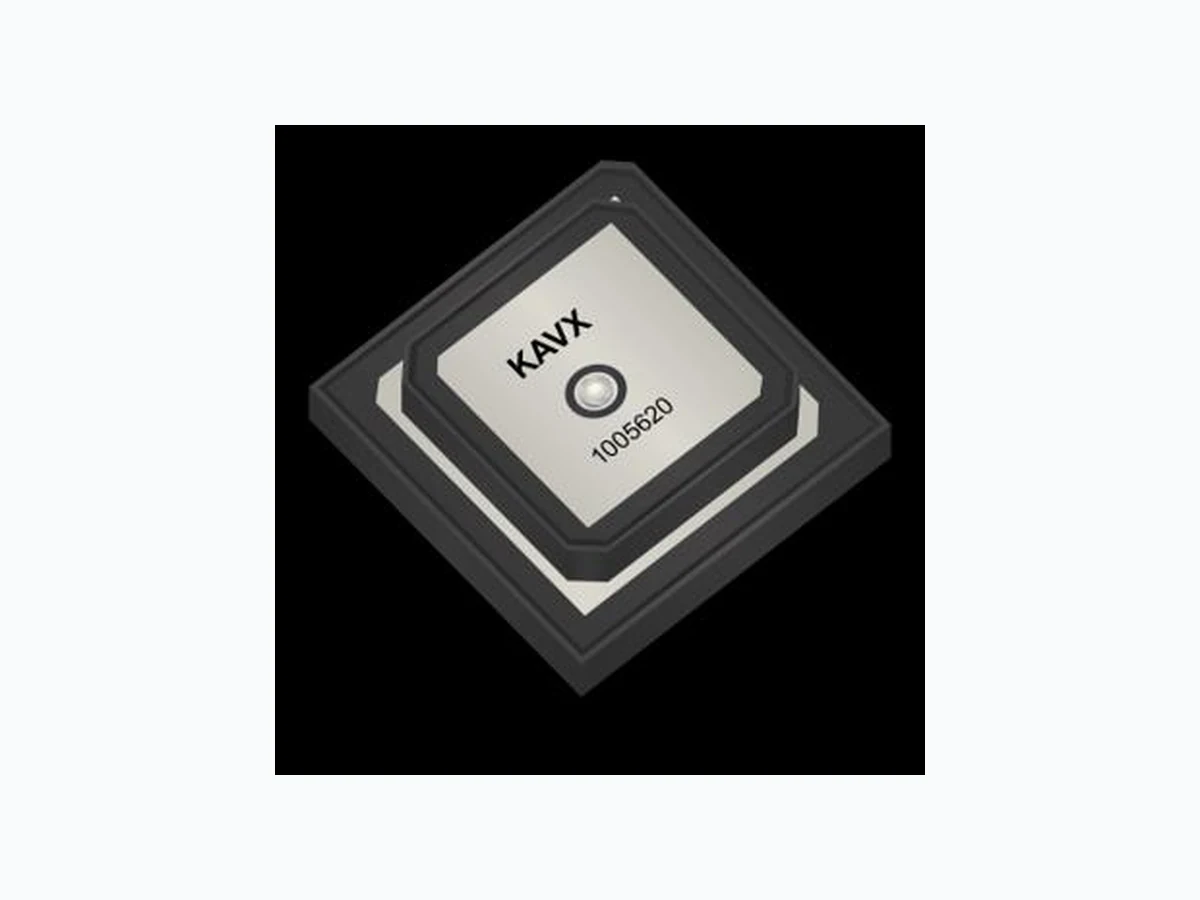
KYOCERA AVX antennas deliver on the key needs of device designers for higher functionality and performance in smaller/thinner designs. This antenna is mounted using double sided adhesive and through-hole solder pin. These innovative antennas provide compelling advantages for GPS L1 & L5 enabled devices. DATASHEET Part No. 1005620 Product: GPS L1 & L5 Ceramic Patch Antenna Ordering Part Number 1005620 Size (mm) 25.0 x 25.0 x 4.16 (Overall) 20 x 20 x 2.0 (Top Patch) Mounting Adhesive tape and solder pin Weight (grams) 9.6 Packaging Plastic Tray Mechanical Specifications & Ordering Part Number KEY BENEFITS Reduced Costs and Time-to- Market Standard antenna eliminates design fees and cycle time associated with a custom solution; getting products to market faster. Quicker Time-to-Market By optimizing antenna size, performance and emissions, customer and regulatory specifications are more easily met. Environmental Compliance Products are the latest RoHS version compliant.
APPLICATIONS
- M2M / IoT devices
- Security (Defense, Marine)
- Telematics devices
- Agriculture
- Geo-tracking
- Autonomous Vehicles
- Vehicle tracking/fleet management systems,
- Navigation devices
- Fitness trackers GPS L1 & L5 Ceramic Patch Antenna
1584 MHz & 1176 MHz
1584 ±2 MHz GPS L5 1176 ±2 MHz Center Frequency fₒ 1584 MHz 1176 MHz Return Loss ˂ -10 dB < -10 dB Zenith Gain 3.3 dBic 0.4 dBic Axial Ratio < 3 dB Polarization R.H.C.P Impedance 50 Ω www.KYOCERA-AVX.com5/12/2022 Proprietary Electrical Specifications Typical Characteristics, on 70 x 70 mm ground plane Part No. 1005620 GPS L1 & L5 Ceramic PatchAntenna Supports: GNSS systems, Global antenna embedded systems, Satellite positioning systems
GPS L1 & L5 Ceramic Patch Antenna Specifications. KYOCERA AVX produces a wide variety of standard and custom antennas to meet user needs DATASHEET | Part No. 1005620 © 2022 KYOCERA AVX tel +(1) 858.550.3820 email: eth.info@kyocera-avx.com
1 Avx Blvd, Fountain Inn, SC 29644
Frequency (MHz) Return Loss (dB) Frequency (MHz) Peak Gain (dBic) Frequency (MHz) Return Loss and Peak Gain Plots Typical performance on 70 x 70 mm PCB
GPS L1 & L5 Ceramic Patch Antenna Specifications. KYOCERA AVX produces a wide variety of standard and custom antennas to meet user needs DATASHEET | Part No. 1005620 © 2022 KYOCERA AVX tel +(1) 858.550.3820 email: eth.info@kyocera-avx.com Axial Ratio, R.H.C.P Plots Typical performance on 70 x 70 mm PCB Measured @ 1176 MHz and 1585 MHz Axial Ratio Phi = 0 R.H.C.P.
GPS L1 & L5 Ceramic Patch Antenna Specifications. KYOCERA AVX produces a wide variety of standard and custom antennas to meet user needs DATASHEET | Part No. 1005620 © 2022 KYOCERA AVX tel +(1) 858.550.3820 email: eth.info@kyocera-avx.com Antenna Radiation Patterns Typical performance on 70 x 70 mm PCB Measured @ 1176 MHz and 1585 MHz
GPS L1 & L5 Ceramic Patch Antenna Specifications. KYOCERA AVX produces a wide variety of standard and custom antennas to meet user needs DATASHEET | Part No. 1005620 © 2022 KYOCERA AVX tel +(1) 858.550.3820 email: eth.info@kyocera-avx.com Typical antenna dimensions (mm) Part Number A B C Top View Side View Adhesive Liner View (Bottom) CA B