

 Download PDF
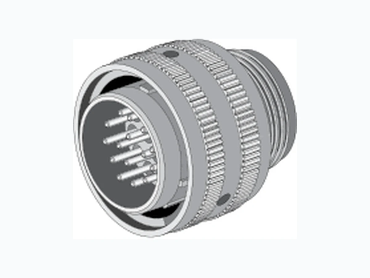
10-503140-032 AMPHENOL
Document overview
- Manufacturer or author: Provided By digicamel.com
- PDF pages: 437
Technical content
Sidney, NY 13838-1395 Phone: 800-678-0141 or 607-563-5011 Fax: 607-563-5157 www.amphenol-aerospace.com Amphenol Circular Interconnects2010 Amphenol
- Aluminum
- Stainless Steel/Firewall
- Composite
- Printed Circuit Board Connectors
- High Speed Connectors
- EMI Filter/Transient * Fiber Optics
- Full Complement of Contacts
- Accessories 2010 AmphenolAerospace The Interconnection Leader 12-C3 Amphenol
- Aluminum
- Stainless Steel/Firewall
- Composite 2010 12-C3 Circular Interconnects Circular Interconnects Circular Interconnects Circular Interconnects Circular Interconnects Circular Interconnects Circular Interconnects Circular Interconnects Circular Interconnects Circular Interconnects Circular Interconnects Circular Interconnects Circular Interconnects Circular Interconnects Circular Interconnects Circular Interconnects Circular Interconnects Circular Interconnects Circular Interconnects Circular Interconnects Circular Interconnects Circular Interconnects Circular Interconnects Circular Interconnects Circular Interconnects Circular Interconnects Circular Interconnects Circular Interconnects Circular Interconnects Circular Interconnects Circular Interconnects Circular Interconnects Circular Interconnects Circular Interconnects Circular Interconnects Circular Interconnects Circular Interconnects Circular Interconnects Circular Interconnects Circular Interconnects Circular Interconnects Circular Interconnects Circular Interconnects Circular Interconnects Circular Interconnects Circular Interconnects Circular Interconnects Circular Interconnects Circular Interconnects Circular Interconnects Circular Interconnects Circular Interconnects Circular Interconnects Circular Interconnects Circular Interconnects Circular Interconnects Circular Interconnects Circular Interconnects Circular Interconnects Circular Interconnects Circular Interconnects Circular Interconnects Circular Interconnects Circular Interconnects Circular Interconnects Circular Interconnects Circular Interconnects Circular Interconnects Circular Interconnects Circular Interconnects Circular Interconnects Circular Interconnects Circular Interconnects Circular Interconnects Circular Interconnects Circular Interconnects Circular Interconnects Circular Interconnects Circular Interconnects Circular Interconnects Circular Interconnects Circular Interconnects Circular Interconnects Circular Interconnects Circular Interconnects Circular Interconnects Circular Interconnects Circular Interconnects Circular Interconnects Circular Interconnects Circular Interconnects Circular Interconnects Circular Interconnects Circular Interconnects Circular Interconnects Circular Interconnects Circular Interconnects Circular Interconnects Circular Interconnects Circular Interconnects Circular Interconnects Circular Interconnects Circular Interconnects Circular Interconnects Circular Interconnects Circular Interconnects Circular Interconnects Circular Interconnects Circular Interconnects Circular Interconnects Circular Interconnects Circular Interconnects Circular Interconnects Circular Interconnects Circular Interconnects Circular Interconnects Circular Interconnects Circular Interconnects Circular Interconnects Circular Interconnects Circular Interconnects Circular Interconnects Circular Interconnects Circular Interconnects Circular Interconnects Circular Interconnects Circular Interconnects Circular Interconnects Circular Interconnects Circular Interconnects Circular Interconnects Circular Interconnects Circular Interconnects Circular Interconnects Circular Interconnects Circular Interconnects Circular Interconnects Circular Interconnects Circular Interconnects Circular Interconnects Circular Interconnects Circular Interconnects Circular Interconnects Circular Interconnects Circular Interconnects Circular Interconnects Circular Interconnects Circular Interconnects Circular Interconnects Circular Interconnects Circular Interconnects Circular Interconnects Circular Interconnects Circular Interconnects Circular Interconnects Circular Interconnects Circular Interconnects Circular Interconnects Circular Interconnects Circular Interconnects Circular Interconnects Circular Interconnects Circular Interconnects Circular Interconnects Circular Interconnects Circular Interconnects Circular Interconnects Circular Interconnects Circular Interconnects Circular Interconnects Circular Interconnects Circular Interconnects Circular Interconnects Circular Interconnects Circular Interconnects Circular Interconnects Circular Interconnects Circular Interconnects Circular Interconnects Circular Interconnects Circular Interconnects Circular Interconnects Circular Interconnects Products for Military, Aerospace and Harsh Environments 12-C3
Contact Amphenol Aerospace for more information at 800-678-0141 • www.amphenol-aerospace.com AmphenolAerospace 1 2648283723 III501526500 PylePrinted Circuit Board EMI Filter TransientFiber OpticsOptions Others Matrix Pyle Crimp Rear Release Matrix Matrix 2 High Speed Contacts 38999 I II IIISJT CONTACT US: Amphenol Aerospace 40-60 Delaware Avenue Sidney, NY 13838-1395 Customer Service: Mon.-Friday 8 am - 5 pm Phone: (800)678-0141 Fax: (607)563-5157 Online: www.amphenol-aerospace.com Amphenol Aerospace, a Division of Amphenol Corporation, is one of the largest manu- facturers of interconnect products in the world for the Military, Commercial Aerospace and Industrial markets. Amphenol designs, manufactures and markets circular and rectangular, electronic, fiber optic, EMI/EMP filter, and a variety of special applications connectors and interconnect systems. Our 675,000 square foot facility is nestled at the foothills of the Catskill Mountains in Sidney NY . The Amphenol complex houses state-of-the-art manufacturing technologies including CNC machining, die-casting, molding, impact and extruding, plating, screw machining and process controls. Our fully equipped material evaluation lab and engineering organization, utilizing the latest in computer aided design software and analysis tools, allows us to design, test, and qualify interconnect systems. Amphenol’s interconnect products are supplied to thousands of OEMs worldwide and are supported by our worldwide sales and engineering force, including the largest global network of electronic distributors. The Amphenol Aerospace Division consists of the interconnect facility in NY; two facilities in NH that manufacture electrical backplanes, rigid boards and flex assemblies; an interconnect facility in Toronto, Canada; and satellite assembly plants in Mexico and China. AMPHENOL AEROSPACE’S PHILOSOPHY: As a basic business philosophy, Amphenol Aerospace is dedicated to concentrating on those advanced and challenging market segments that demand an extraordinary level of supplier support and reaction. Our approach to implement this strategy is based on the following key principles: FOCUS: Concentrate all resources on serving a limited number of tightly defined markets, and understanding the needs of those markets. INNOVATION: Provide these markets new, creative solutions in both products and services. RESPONSIVENESS: Identify and respond to the market and product needs more rapidly than any other supplier. Performance is the sum of these principles. It is the measure of how well we continually and consistently implement our basic strategy and key principles. ABOUT AMPHENOL AEROSPACE: CUSTOMIZED INTERCONNECT PACKAGES: Amphenol Corporation’s broad technical, product and manufacturing resources enable Amphenol Aerospace to provide exceptional performance in the area of customized system development-application specific packaging which blends both Corporate and Amphenol Aerospace products and design innovations. We provide customers with rapid, well engineered and cost-effective custom interconnect solutions. QUALITY ASSURANCE: Amphenol Aerospace has been awarded both AS9100 - Revision B and ISO9001:2000 quality assurance certifications. About Amphenol® Aerospace
Contact Amphenol Aerospace for more information at 800-678-0141 • www.amphenol-aerospace.com AmphenolAerospace 38999
2648283723 III501526500 PylePrinted
TransientFiber OpticsOptions Others Matrix 2 Matrix Pyle Crimp Rear Release Matrix I II III High Speed Contacts SJT MIL-DTL-38999 Series III, TV Tri-Start Amphenol Aerospace Quick Reference Pages 4-7 Shell & Insert Chart 8-14 Insert Arrangements 17-44 TV Section 89-108 Accessories, Contacts, and Tools MIL-DTL-38999 Series II, JT Pages 4-7 Shell & Insert Chart 8-14 Insert Patterns 45-66 JT Section 89-108 Accessories, Contacts, and Tools MIL-DTL-38999 Series I, LJT Pages 4-7 Shell & Insert Chart 8-14 Insert Patterns 67-80 LJT Section 89-108 Accessories, Contacts, and Tools SJT Pages
84 Shell & Insert Chart
89-108 Accessories, Contacts, and Tools MIL-DTL-26500 Pyle Pages 203,204 Insert Patterns 209-223 Shell Styles 226-235 Accessories, Contacts, and Tools Printed Circuit Board Pages
239 Shell & Insert Chart
241-255 Insert Arrangements 256-275 Shell Styles
276 Stand-off Adapter
288,289 How to Order 290-331 Shell Styles 332-338 Adapters, MOV, Diode, ESA and Specials Fiber Optics High Speed Contacts Options Others MIL-DTL-5015 Crimp Rear Release Matrix Pages 172-173 Shell & Insert Chart 174-182 Insert Patterns 186-192 Shell Styles 194-197 Accessories, Contacts, and Tools MIL-DTL-83723 Matrix Pages
124 Shell & Insert Chart
125, 126 Insert Arrangements 128-135 Shell Styles
136 Accessories, Contacts,
111 Shell & Insert Chart
112, 113 Insert Arrangements 116-118 Shell Styles
119 Accessories, Contacts,
347 Shell & Insert Chart
348,349 Insert Patterns 350-360 Shell Styles 361-364 Accessories, Tools and Cable Systems Pages 372-375 Cable Usage Guide
376 Overview
377-406 MIL-DTL-38999 Contacts 407-414 MIL-DTL-5015 & MIL-DTL-22992 Pages 415-431 Additional Circulars 432-435 Additional Rectangular MIL-DTL-83723 Pyle Pages
146 Shell & Insert Chart
147,148 Insert Arrangements 157-165 Shell Styles 166-169 Accessories, Contacts, and Tools
Contact Amphenol Aerospace for more information at 800-678-0141 • www.amphenol-aerospace.com AmphenolAerospace 3 2648283723 III501526500 PylePrinted Circuit Board EMI Filter TransientFiber OpticsOptions Others Matrix Pyle Crimp Rear Release Matrix Matrix 2 High Speed Contacts 38999 I II IIISJT Amphenol Aerospace New, Featured Products New/Featured Filter Connector with High Density Patterns Page 289 New High Density Patterns are available in Filter 38999 connec- tors in standard Mil-Spec or filter length shells. They provide 30% more contact that standard insert arrangement patterns. See page 43 for ordering information. Breakaway Hybrid, Low Profile Lanyard Release Plug Page 42 New Hybrid Lanyard Breakaway Fail Safe Connector with a composite thermoplastic outer operating sleeve for greater durability. New HD38999 (High Density, Crimp) Plugs and receptacles Page 43, 44 The HD38999 family of connectors was designed to work with existing Mil-specified 38999 shells. The HD38999 has 30% more contacts, it still performs to minimum electrical requirements of standard 38999 connectors. MT Ferrule Connectors Page 359 Amphenol offers a multi-channel circular connector with high density MT fiber optics. High fiber density in a relatively small circular connector package with all the advantages of the MIL- DTL-38999 series III connector. ARINC 801 Connectors Page 356 Designed for use in Amphenol ARINC 801 fiber optic connectors - manufactured to comply with ARINC 801. Genderless terminus allows for use on both sides of a connector. Matrix MIL-DTL-5015 with RADSOK® Contacts Page 193 A special design of the Matrix MIL-DTL-5015, Series II connectors has added high amperage with the RADSOK ® contacts in the plug instead of standard rear release crimp contacts. Solution: Navy F-18 program needed a break away plug that would have greater durability in weapons release application. Solution: 30% more contact density in 38999 Series III Shells Solution: Higher amperage capability in Matrix MIL-DTL-5015 Solution: Higher contact density and custom stand-off shell designs Solution: Fiber Optic Termini & Connector that meet ARINC specifications Solution: Higher Density Fiber Optics in MIL-DTL-38999 Amphenol has become the leader in interconnection products through its long history of engineering expertise for product solution solving. New and innovative solutions are under development every day within our highly skilled engineering departments who are teamed with marketing product managers and production specialists. They are always striving to meet new customer requirements in ever changing markets. The teams have a customer-driven approach to produce the end result: quality interconnect products that meet or exceed customer demands. New/Featured New/Featured New/Featured New/Featured New/Featured
TransientFiber OpticsOptions Others Matrix 2 Matrix Pyle Crimp Rear Release Matrix I II III High Speed Contacts SJT Contact Amphenol Aerospace for more information at 800-678-0141 • www.amphenol-aerospace.com AmphenolAerospace JT/LJT Hermetics Contact Size JT II LJT I TV III TV III Solder Crimp Class H Class Y TV* Service Rating Total Contacts 22D 22M 22 2016 12 12 (Coax) (Power) (Coax) 8†† (Twinax) 8-2■ P M 2 2 8-3■ X NA P P M 3 39-3■ X 9-5★■ Grounded 1 1 8-6 X X P P M 6 69-6 X X P P 9-7■ X M 7 7 9-22■ X I 2 2 8-35 X P P M 6 69-35 9-35 A35 X P P P 8-44 X P P M 4 49-44 X 9-94 ■ ✦ M 2 2 8-97■ X M 4 2 2 8-98 S X P P I 3 39-98 9-98 A98 X X P P P 11-2★ 11-2★ B2 X P I 2 2 10-4 3 I 4 411-4 11-4 X S/2 10-5 X X P P I 5 511-5 11-5 B5 X X P 11-6■ S I 6 6 10-13 X X P/S P/S M 13 1311-13 X X P/S P/S 10-35 X P/S P/S M 13 1311-35 11-35 B35 X P/S P/S P 11-54 ■ X ✦ II 4 4 10-98 X X P/S P/S I 6 611-98 11-98 B98 X X P/S P/S P 10-99 X P P I 7 711-99 11-99 B99 P X P 12-3 X X ✦ P P II 3 313-3■ P 12-4 X X P P I 4 413-4★ 13-4★ C4 X X P P P 12-8 X X P P I 8 813-8 13-8 C8 X X P P P 13-13■ I, Fiber Optic 4 2 2 12-22 X P/S P/S M 22 2213-22 X X P/S P/S 12-35 X P/S P/S M 22 2213-35 13-35 C35 X P/S P/S P 13-63■ ✦ l 4 2 2 12-98 X X P/S P/S I 10 1013-98 13-98 C98 X X P/S P/S P 14-4■ 2 I 4 415-4■ 15-4■ 2 ✦ 14-5 X X P P II 5 515-5★ 15-5★ D5 X X P P P 14-15 X X P P I 15 14 1 15-15 15-15 D15 X X P/S P/S P I 15 14 1 MIL-DTL-38999, Series I LJT, II JT, III TV Insert Availability and Identification Chart Series Series Series Military X Completely tooled.
- Majority of tooling is completed (contact Amphenol Aerospace for availability). ✦ Not tooled for 02-R. P Available with Pin contacts only S Available with Socket contacts only P/S Available with Pin contacts or Socket contacts ★ Ground plane proprietary option available. Arrg. 9-5 is exclusively ground plane type. ■ Not Mil-Qualified. ✧ 21-75 is Mil-Qualified with twinax contacts only. Note: MS connector 21-75 is supplied with size 8 twinax. Commercial connector 21-75 is supplied with size 8 coax. * Hermetic inserts - solder termination standard. (Contact Amphenol Aerospace for optional PCB or eyelet termination). Two size 16 contacts dedicated to fiber optics. See the Fiber Optic section for more information. * For use in MIL-STD-1760 applications (see pages 40 & 41). † For RG 180/U and RG 195/U cables only. †† Size 8 Coax and Twinax are interchangeable. (2) Not Tooled for RP or 02RE (3) Pin inserts only, not tooled for RP or 02RE (Consult Sidney, NY for avail.) (5) MS Connector 21-79 has provision for two size 8 coax contacts. Coax contacts are not supplied unless specified by customer.
83723 III
26500 Pyle
I II III SJT Contact Amphenol Aerospace for more information at 800-678-0141 • www.amphenol-aerospace.com AmphenolAerospace MIL-DTL-38999, Series I LJT, II JT, III TV Insert Availability and Identification Chart JT/LJT Hermetics Contact Size Solder Crimp Class H Class Y TV* Service Rating Total Contacts 22D 22M 22 20 16 12 12 (Coax) (Power) (Coax) 8†† (Twinax) 14-18 X X P/S P/S I 18 1815-18 15-18 D18 X X P/S P/S P 14-19■ X X I 19 1915-19 15-19 D19 X P P P 14-35 X P P M 37 3715-35 15-35 D35 X P/S P/S P 14-37 X X P P M 37 3715-37 X X P P 14-68■ 2 P P 1 8 815-68■ X 2 14-97■ X P P I 12 8 415-97 15-97 D97 X X P P P 17-2 17-2 E2 X ✦ M 39 38 1 16-6 X P P I 6 617-6 17-6 E6 X P P P 16-8 X X P P II 8 817-8★ 17-8★ E8 X X P/S P/S P 16-13■ 2 I 13 1317-13■ 2 17-22■ 17-22★■ ✦ Coax 4 2 2 17-25■ 2 M 24 22 2 16-26 X X P/S P/S I 26 2617-26 17-26 E26 X X P/S P/S P 16-35 X P P M 55 5517-35 17-35 E35 X X P P P 16-42 X M 42 4217-42■ P 17-52■ X ✦ M 2 2 16-55 X X P/S P/S M 55 5517-55 X X P/S P/S 17-60■ X I/Coax 10 8 2 16-99 X X P P I 23 21 217-99 17-99 E99 X X P P 19-AD■ X ✦ Inst. 17 16 1 18-11 X X P P II 11 1119-11★ 19-11★ F11 X X P P P 19-18 19-18 F18 2 X M 18 14 4 18-28 X X I 28 26 219-28■ 19-28 F28 X P X 18-30 X X I 30 29 119-30■ X P 19-31 ■ X M 15 12 1 2 18-
32 X X P/S P/S I 32 3219-32 19-32 F32 X X P/S P/S P
18-35 X P P M 66 6619-35 19-35 F35 X P P P 18-53 X X M 53 5319-53■ P 18-66 X X P P M 66 6619-66 X P P 19-67■ X 3 S S M 67 67 18-68■ 2 I 18 1819-68■ 3 18-96■ 2 I 9 9 20-1 X P P M 79 7921-1 X P/S P/S 20-2 X M 65 6521-2■ X 20-11■ 3 I 11 1121-11★ 21-11★ G11 X Series Series Series Military JT II LJT I TV III TV III
I II III High Speed Contacts SJT Contact Amphenol Aerospace for more information at 800-678-0141 • www.amphenol-aerospace.com AmphenolAerospace JT/LJT Hermetics Contact Size Solder Crimp H Y TV* Service Rating Total Contacts 22D 22M 22 20 16 12 12 (Coax) (Power) (Coax) 8†† (Twinax) 20-16 X X P/S P/S II 16 1621-16★ 21-16★ G16 X X P P P 21-25■ X I 25 25 21-27■ X I 27 27 21-29 ■ X I 27 19 4 4 20-35 X P P M 79 7921-35 21-35 G35 X P/S P/S P 20-39 X X P P I 39 37 221-39 21-39 G39 X X P P P 20-41 X X P P I 41 4121-41 21-41 G41 X X P/S P/S P 21-75★ 21-75★✧ G75 2 X N M 4 4 (4) 21-79■ 21-79 ■ 2 X II 19 17 2 (5) 22-1 X P/S P/S M 100 10023-1 X P P 22-2 X X P P M 85 8523-2 X X P P 22-14■ 2 ✦ I 14 1423-14■ 23-14 ■ 2 ✦ 22-21 X X P P II 21 2123-21★ 23-21★ H21 X X P P P 22-32 X X P P I 32 3223-32■ X P 23-34■ X I 34 34 22-35 X P/S P/S M 100 10023-35 23-35 H35 X P P P 22-53■ P I 53 5323-53 23-53 H53 X X P/S P/S P 23-54 ■ X M 53 40 9 4 22-55 X X P P I 55 5523-55 23-55 H55 X P 23-97■ X II 16 16 23-99■ X II 11 11 24-1 X P P M 128 12825-1 X P P 24-2 X M 100 10025-2 X 24-4 X P P I 56 48 825-4 25-4 J4 X P 25-7■ 25-7 J7 X M Twinax 99 97 2 25-8★ J8 ✦ Twinax 8 8 25-11* J11 2 ✦ N 11 2 9 25- 17 ■ ✦ M 42 36 6 24-19■ X P P I 19 1925-19★ 25-19★ J19 X P 25-20■ 25-20* J20 2 ✦ N 30 10 13 4 3 24-24 X P P I 24 12 1225-24★ 25-24★ J24 X P P 25-26 ■ ✦ I 25 16 5 4 24-29 X I 29 2925-29★ 25-29★ J29 X X Series Series Series Military MIL-DTL-38999, Series I LJT, II JT, III TV Insert Availability and Identification Chart X Completely tooled. Major ity of tooling is completed (contact Amphenol Aerospace for availability). Not tooled f or 02-R. P A vailable with Pin contacts only S A vailable with Socket contacts only P/S A vailable with Pin contacts or Socket contacts Ground plane propr ietary option available. Arrg. 9-5 is exclusively g round plane type. Not Mil-Qualified. 21-75 is Mil-Qualified with twinax contacts only Her metic inserts - solder termination standard. (Contact Amphenol Aerospace f or optional PCB or eyelet termination). T wo size 16 contacts dedicated to fiber optics. See the Fiber Optic Section f or more information. * F or use in MIL-STD-1760 applications (see pages 40 & 41). F or RG 180/U and RG 195/U cables only. Siz e 8 Coax and Twinax are interchangeable. (2) Not Tooled for RP or 02RE (3) Pin inser ts only, not tooled for RP or 02RE (Consult Sidney, NY for avail.) (4) MS connector 21-75 is supplied with size 8 twinax. Commercial connector 21-75 is supplied with siz e 8 coax. (5) MS Connector 21-79 has pro vision for two size 8 coax contacts. Coax contacts are not supplied unless specified b y customer. JT II LJT I TV III TV III
I II III SJT Contact Amphenol Aerospace for more information at 800-678-0141 • www.amphenol-aerospace.com AmphenolAerospace (Insert arrangements requiring non-standard shells or larger contacts) X Completely tooled. Major ity of tooling is completed (contact Amphenol Aerospace f or availability). Not tooled f or 02-R. P Pin inser ts only (contact Amphenol Aerospace f or socket availability). Ground plane propr ietary option available. Arr angement 9-5 is exclusively ground plane type. Not Mil-Qualified. Her metic inserts - solder termination standard. (Contact Amphenol Aerospace f or optional PCB or e yelet termination). T wo size 16 contacts dedicated to fiber optics. See the Fiber Optic section f or more information. *** F or use in MIL-STD-1760 applications (pgs . 40 & 41). F or RG 180/U and RG 195/U cables only. Siz e 8 Coax and Twinax are interchangeable. Note: 25L-3 and 25L-7 require longer shells. Select Non-Standard Shell Size - Special Insert Arrangement (Not Mil-Spec Qualified) Contact Size Shell Size- Insert Arrg. Crimp Hermetics* Service Rating Total Contacts Comments 22D 20 16 12 9-2 X I 2 Formerly Pyle 2 15-4 X II 4 Formerly Pyle 4 15-25 X M 25 Formerly Pyle 22 3 17-20 X M 20 Formerly Pyle 16 4 21-12 X I 12 Formerly Pyle 3 9 21-21 X M/Inst. 41 Improved sealing 32 9 21-99 X M 16 Formerly Pyle 5 11 25-92 X M 101 Formerly Pyle 92 9 25-97 X M 42 Formerly Pyle 26 3 13 Contact Size Shell Size- Insert Arrg. Crimp Hermetics* Service Rating Total Contacts 20 8 4 0 25-16 X M 8 6 2 25L-3 X II 3 1 2 25L-7 X II 7 7 33-3 X II 3 1 2 33-5 X II 5 5 33-6 X II 6 2 4 37-5 X II 4 4 Select Shell Size - Special Insert Arrangement (Not Mil-Spec Qualified) JT/LJT Hermetics Contact Size Solder Crimp H Y TV* Service Rating Total Contacts 22D 22M22 20 16 12 12 (Coax) (Power) (Coax) 8†† (Twinax) Quadrax 24-35 X P P New 128 12825-35 25-35 J35 X P P P M 24-37 X I 37 3725-37★ 25-37★ J37 X 24-43■ 3 I 43 23 2025-43 25-43 J43 X 2 ✦ 25-46 25-46 J46 2 ✦ I 46 40 4 2 24-61 X X P P I 61 6125-61 25-61 J61 X X P P P 25-62■ X ✦ I 12 8 4 25-90 J90 ✦ I 46 40 4 2 25-F4 ■ X M/I 66 49 13 4 Series Series Series Military TV Series III MIL-DTL-38999, Series I LJT, II JT, III TV Insert Availability and Identification Chart X Completely tooled. Not tooled f or 02-R. P Pin inser ts only (contact Amphenol Aerospace for socket availability). Ground plane propr ietary option available. Arrg. 9-5 is exclusively g round plane type. Not Mil-Qualified. JT II LJT I TV III TV III
TransientFiber OpticsOptions Others Matrix 2 Matrix Pyle Crimp Rear Release Matrix I II III High Speed Contacts SJT Contact Amphenol Aerospace for more information at 800-678-0141 • www.amphenol-aerospace.com AmphenolAerospace Front face of pin inserts illustrated A B C D E F A B C DE F G H A D C B A B C D E FG HJ KL M N P R S T U V WXY Z a b c MIL-DTL-38999, Series I LJT, II JT, III TV Insert Arrangements A B C 1 5 6 7 A B 5 1 4 A B CD C A B A B A B C D A B CD E F 1 1213 1213 A B CD E F A B CD E F G A B C A B C D A B C D E F G H 22 A B C D E F G H JK A B CD EA BC D A B C D E F G H J K L M N P R A B C D EFG H J K L M N P RS T U A B C D EF GH J K L M N P R ST U V 2131 A B C D EF G H J K L M 2131 A B C DE F G H CONTACT LEGEND 8 10 12 16 20 22 22M 22D A BCD E Shell Size & Insert Arrg. for: Series II JT 8-2 8-3 8-6 8-35 8-44 8-97 8-98 Series I LJT 9-3 9-6 9-7 9-22 9-35 9-44 9-98 Series III TV 9-5 9-35 9-94 9-98 Service Rating M M Grounded M M I M M M M I Number of Contacts 2 3 1 6 7 2 6 4 2 2 2 3 Contact Size 20 20 8 Twinax 22M 22M 20 22D 22 20 22M 20 20 AB Shell Size & Insert Arrg. for: Series II JT 10-4 10-5 10-13 10-35 10-98 10-99 12-3 Series I LJT 11-2 11-4 11-5 11-6 11-13 11-35 11-98 11-99 13-3 Series III TV 11-2 11-4 11-5 11-35 11-54 11-98 11-99 Service Rating I I I I M M II I I II Number of Contacts 2 4 5 6 13 13 4 6 7 3 Contact Size 16 20 20 20 22M 22D 22D 20 20 16 Shell Size & Insert Arrg. for: Series II JT 12-4 12-8 12-22 12-35 12-98 14-4 14-5 14-15 Series I LJT 13-4 13-8 13-22 13-35 13-98 15-4 15-5 15-15 Series III TV 13-4 13-8 13-35 13-63 13-98 15-4 15-5 15-15 Service Rating I I M M I I I II I Number of Contacts 4 8 22 22 2 2 10 4 5 14 1 Contact Size 16 20 22M 22D 16 12 20 12 16 20 16 Shell Size & Insert Arrg. for: Series II JT 14-18 14-19 14-35 14-37 14-68 14-97 Series I LJT 15-18 15-19 15-35 15-37 15-68 15-97 17-2 Series III TV 15-18 15-19 15-35 15-97 17-2 Service Rating I I M M I I M Number of Contacts 18 19 37 37 8 8 4 38 1 Contact Size 20 20 22D 22M 16 20 16 22D 8 Twinax Shell Size & Insert Arrg. for: Series II JT 16-6 16-8 16-13 16-26 Series I LJT 17-6 17-8 17-13 17-22 17-25 17-26 Series III TV 17-6 17-8 17-22 17-26 Service Rating I II I Coax M I Number of Contacts 6 8 13 2 2 22 2 26 Contact Size 12 16 16 12 Coax 8 Coax 22D 8 Coax 20 A B D C A B C D EF G H J K L N M 1 2 5678 11 12 13 14 15 16 B A AB C D
9 2648283723 III501526500 PylePrinted Circuit Board EMI Filter TransientFiber OpticsOptions Others Matrix Pyle Crimp Rear Release Matrix Matrix 2 High Speed Contacts 38999 I II IIISJT Contact Amphenol Aerospace for more information at 800-678-0141 • www.amphenol-aerospace.com AmphenolAerospace CONTACT LEGEND Front face of pin inserts illustrated A B C D E FG HJ KL M N P R S T U VW X Y Z A B C D E F G H J K L A B C D E F G H J K L M N PR S 8 1 0 1 2 1 6 2 0 22D MIL-DTL-38999, Series I LJT, II JT, III TV Insert Arrangements Shell Size & Insert Arrg. for: Series II JT 16-35 16-42 16-55 16-99 18-11 Series I LJT 17-35 17-42 17-55 17-99 19-11 Series III TV 17-35 17-52 17-60 17-99 19-11 Service Rating M M M M I/Coax I II Number of Contacts 55 42 2 55 8 2 21 2 11 Contact Size 22D 22 8 Twinax 22M 22D 8 Coax 20 16 16 Shell Size & Insert Arrg. for: Series II JT 18-28 18-30 18-32 18-35 Series I LJT 19-18 19-28 19-30 19-32 19-35 Series III TV 19-18 19-28 19-31 19-32 19-35 Service Rating M M I M I M Number of Contacts 14 4 26 2 29 1 2 1 12 32 66 Contact Size 22D 8 Twinax 20 18 20 16 8 Coax 12 22D 20 22D Shell Size & Insert Arrg. for: Series II JT 18-53 18-66 18-68 18-96 Series I LJT 19-53 19-66 19-67 19-68 Series III TV Service Rating M M M I I Number of Contacts 53 66 67 18 9 Contact Size 22 22M 22M 16 12 Shell Size & Insert Arrg. for: Series II JT 20-1 20-2 20-11 20-16 Series I LJT 21-1 21-2 21-11 21-16 Series III TV 19-AD 21-11 21-16 Service Rating Inst. M M I II Number of Contacts 16 1 79 65 11 16 Contact Size 20 8 Twinax 22M 22 12 16 A B C D E F G H J K L A B C D E F G H R J K L M N P S T U V W X Y Z a b c d e A B C EK M N R S U V W gh f A B C D E F G H J K L M N P R S T U V W X Y Za bc d e f g h j A B C D E F G H J K L M N P R S T U A B C D E F GHJK L M N P R S T U V W XY Za b c d e g f A BL CK DJ EH F GR U M T N S P A BH C D F E G J 5253 17 25 24 31 A B 9 3 6 4 215 314 11 8 710 8 9 A
TransientFiber OpticsOptions Others Matrix 2 Matrix Pyle Crimp Rear Release Matrix I II III High Speed Contacts SJT Contact Amphenol Aerospace for more information at 800-678-0141 • www.amphenol-aerospace.com AmphenolAerospace 1 2 91011 2627 61 71 CONTACT LEGEND Front face of pin inserts illustrated A B C D E F G H JKL M N P R S T U V W X Y Z a b c d e f g h i j k m n p q r A B C D E F G H J KLM N P R S T U V W X Y Z a b c def g h i j k m n pq r s t A BC D A B C D E F G H J K L M N P R S T U V A B CD E F A BK CJ LP MN DH EG F A B C D E F G H J K L M P R S N TU V W X A B C D E FGH J K L M N P R S T U VWX Y Z a b c d ef g h j 8 1 0 1 2 1 6 2 0 22D MIL-DTL-38999, Series I LJT, II JT, III TV Insert Arrangements Shell Size & Insert Arrg. for: Series II JT 20-35 Series I LJT 21-25 21-27 21-35 Series III TV 21-29 21-35 Service Rating I I I M Number of Contacts 25 27 19 4 4 79 Contact Size 20 20 20 16 12 22D A B C D E F G HJK L M N P R S T UV W X Y Z a b A B C D E F G H J K L M N P R S T U VW X Y Z a b cd Shell Size & Insert Arrg. for: Series II JT 20-39 20-41 22-1 Series I LJT 21-39 21-41 21-75 21-79 23-1 Series III TV 21-39 21-41 21-75 21-79 Service Rating I I N II M Number of Contacts 37 2 41 4 17 (See Note) 100 Contact Size 20 16 20 (See Note) 22D 22M Shell Size & Insert Arrg. for: Series II JT 22-2 22-14 22-21 22-32 Series I LJT 23-2 23-6 23-14 23-21 23-32 Series III TV 23-6 23-14 23-21 Service Rating M M I II I Number of Contacts 85 6 14 21 32 Contact Size 22 8 Twinax 12 16 20 100 Note: MS connector 21-75 is supplied with four size 8 twinax contacts. Commercial connector 21-75 is supplied with four size 8 coax contacts. MS connector 21-79 has provision for two size 8 coax contacts. Coax contacts are not supplied unless specified by customers.
11 2648283723 III501526500 PylePrinted Circuit Board EMI Filter TransientFiber OpticsOptions Others Matrix Pyle Crimp Rear Release Matrix Matrix 2 High Speed Contacts 38999 I II IIISJT Contact Amphenol Aerospace for more information at 800-678-0141 • www.amphenol-aerospace.com AmphenolAerospace Front face of pin inserts illustrated CONTACT LEGEND *** For use in MIL-STD-1760 applications (see pages 40 and 41). A B C D E F G H J K LM N P R S T U V W X Y Z a b c d e f g h k mnp q r t u v w x y zs JJ KK L L A A B BC C D D E E FF G G H H 25 75 A B C D E F G H 8 1 0 1 2 1 6 2 0 22D Shell Size & Insert Arrg. for: Series II JT 22-35 22-53 Series I LJT 23-34 23-35 23-53 Series III TV 23-35 23-53 23-54 Service Rating I M I M Number of Contacts 34 100 53 40 9 4 Contact Size 20 22D 20 22D 16 12 Shell Size & Insert Arrg. for: Series II JT 22-55 24-1 Series I LJT 23-55 23-97 23-99 25-1 Series III TV 23-55 Service Rating I II II M Number of Contacts 55 16 11 128 Contact Size 20 16 16 22M A B C D E F G HJ K L M N P R S T U V W X Y Za b c d e f g h k m n p q r s t A B u v w x y z A B C C D D E E FF G G HH 1 2 3 11121314 1516 2223 24 25 2627 3334 363738 45 46 4849 50 A B C D E F G H JKL M N P R S T U V W X Y Z a b c d ef g h i j k m n p q r s t vw x y z AA BB C C u D DE E FF G G H H Shell Size & Insert Arrg. for: Series II JT 24-2 24-4 Series I LJT 25-2 25-4 25-7 Series III TV 25-4 25-7 25-8 Service Rating M I M Twinax Number of Contacts 100 48 8 97 2 8 Contact Size 22 20 16 22D 8 Twinax 8 Twinax A B C D E F G H JK L M N P R S T U V W X Y Z a b c d e f g h j k l 9596 100 A B C D E F G H J K L M N P R S A B C D E F G H J K L 104 105 114 115 121 125 40 51 100 MIL-DTL-38999, Series I LJT, II JT, III TV Insert Arrangements
TransientFiber OpticsOptions Others Matrix 2 Matrix Pyle Crimp Rear Release Matrix I II III High Speed Contacts SJT Contact Amphenol Aerospace for more information at 800-678-0141 • www.amphenol-aerospace.com AmphenolAerospace Contact Amphenol Aerospace for more information at 800-678-0141 • www.amphenol-aerospace.com AmphenolAerospace A B C D E F G H J KL A B C D E F G H JKL M N P R S T U V W XY Z a b c d e f g h k m n p q r s t uv w A B C D E F GH J K L M N P R ST U V A B C D E F G H J K L M N P R S T U VWX Y Z A B C D E F G HJ K L M N P R S T U VW X Y Z a 18 19 20 2223 Front face of pin inserts illustrated CONTACT LEGEND † Coax contacts for RG180/U or RG195/U cable. A B C D E F G HJ K L M N P R S T U V W XY Z a b c d e f 104 105 114 115 121 125 128 A B C D E F G H JKLM N P R S T U V W X Y Z a b c d e fgh k m n p q r s t u v w xy z AA 8 1 0 1 2 1 6 2 0 22D Shell Size & Insert Arrg. for: Series II JT 24-19 Series I LJT 25-11 25-19 25-20 Series III TV 25-11* 25-17 25-19 25-20* Service Rating N M I N Number of Contacts 2 9 36 6 19 10 13 3 4 Contact Size 20 10 22D 8 Twinax 12 20 16 8 Twinax 12 Coax Shell Size & Insert Arrg. for: Series II JT 24-24 24-29 24-35 Series I LJT 25-24 25-29 25-35 Series III TV 25-24 25-26 25-29 25-35 Service Rating I I I M Number of Contacts 12 12 16 5 4 29 128 Contact Size 16 12 20 12 8 Coax 16 22D Shell Size & Insert Arrg. for: Series II JT 24-37 25-43 Series I LJT 25-37 25-43 25-46 Series III TV 25-37 25-43 25-46 Service Rating I I I Number of Contacts 37 23 20 40 4 2 Contact Size 16 20 20 16 8 Coax (With Matched Impedance) A B C D E F G H J K L M N P R S T U V W X Y Z ab c d e f g h k m np q r A B C D E F G H J K LMN P R S T U V W X Y Z a b c d e f g h k m n p q r st u v w x MIL-DTL-38999, Series I LJT, II JT, III TV Insert Arrangements
I II III SJT Contact Amphenol Aerospace for more information at 800-678-0141 • www.amphenol-aerospace.com AmphenolAerospace Front face of pin inserts illustrated Front face of pin inserts illustrated CONTACT LEGEND NOTE: Some specials shown here were formerly known as Pyle arrangements. Consult Amphenol for how to order information for connectors with these inserts. For further information on special arrangements consult Amphenol Aerospace, Sidney NY . * Pyle 15-4 does not mate with Amphenol Tri-Start 15-4 insert. B A D C B A 910 1920 A D C B 15 14 11 10 9 8 3 2 J H G F E K D L C B A M 9 10 A B C DE F G H J 11 12 1718 23 24 25 26 2728 3031 A J H G F E D C B M L K S RP N 4667 101 78 66 56 45 35 23 12 MA LB N KC JD HE GF YW XaU Z V r m p n ksb c d e P R S T jw hgf u vt 81 01 21 62 0 22D Shell Size & Insert Arrg. for: Series II JT 24-61 Series I LJT 25-61 Series III TV 25-61 25-62 25-90 25-F4 Service Rating I I I Size 22D=M, Balance =I Number of Contacts 61 8 4 40 4 2 49 13 4 Contact Size 20 16 8 20 16 8 Twinax 22D 16 12 A B C D E F G H JK LM N a P R S T U V W X Y Z b c d e f gh AA k q m n p r s t u v w xy z 60 66 64 37 50 51 41 42 43 38 39 40 29 2726 5463 62 61 3253 52 Shell Size & Insert Arrg. for: Series III TV 9-2 15-4* 15-25 17-20 21-12 21-21 Service Rating I II M M I M/Inst. Number of Contacts 2 4 22 3 16 4 3 9 32 9 Contact Size 20 16 22D 16 22D 12 20 12 22D 12 Shell Size & Insert Arrg. for: Series III TV 21-99 25-92 25-97 Service Rating M M M Number of Contacts 5 11 92 9 26 3 13 Contact Size 22D 12 22D 16 22D 16 12 MIL-DTL-38999, Series I LJT, II JT, III TV Insert Arrangements MIL-DTL-38999, Series III TV Special Insert Arrangements DA CB 1 8 4 5 A B C D E F G H J K LMNP R S T U V W X Y Z a b c d e f g h i jkmn p q r s t u v w x y z BB CC DD EE F F GG HH JJ KK LL MM NN AA PP Front face of socket inserts illustrated
Contact Amphenol Aerospace for more information at 800-678-0141 • www.amphenol-aerospace.com AmphenolAerospace SJT38999 TransientFiber OpticsContactsAccessories Tools Options Others Matrix 2 Matrix Pyle Crimp Rear Release Matrix AmphenolAerospace I II III Contact Amphenol Aerospace for more information at 800-678-0141 • www.amphenol-aerospace.com Front face of pin inserts illustrated CONTACT LEGEND NOTE: Some specials shown here were formerly known as Pyle arrangements. Consult Amphenol for how to order information for connectors with these inserts. Consult Amphenol Aerospace for longer shell drawings. A B C D E FG H A B C A B CD E F G B C A A B C D E A B C D E F A B C D 8 4 022D MIL-DTL-38999, Series III TV Special Insert Arrangements Non-Standard Shells or Large Contacts Shell Size & Insert Arrg. for: Series III TV 25-16 25L-3 25L-7 Service Rating M II II Number of Contacts 6 2 1 2 7 Contact Size 20 4 8 4 8 Shell Size & Insert Arrg. for: Series III TV 33-3 33-5 33-6 Service Rating II II II Number of Contacts 1 2 5 2 4 Contact Size 4 0 4 8 4 Shell Size & Insert Arrg. for: Series III TV 37-5 Service Rating II Number of Contacts 4 Contact Size 0
TransientFiber OpticsOptions Others Matrix Pyle Crimp Rear Release Matrix Matrix 2 High Speed Contacts 38999 I II IIISJT Contact Amphenol Aerospace for more information at 800-678-0141 • www.amphenol-aerospace.com AmphenolAerospace Contact Amphenol Aerospace for more information at 800-678-0141 • www.amphenol-aerospace.com AmphenolAerospace 15Contact Amphenol Aerospace for more information at 800-678-0141 • www.amphenol-aerospace.com AmphenolAerospace MIL-DTL-38999, Series I LJT, II JT, III TV Specifications/ Contacts CONTACT RATING *When tested using silver plated wire. SERVICE RATING Please note that the establishment of electrical safety factors is left entirely in the designer’s hands, since he is in the best position to know what peak voltage, switching surges, transients, etc. can be expected in a particular circuit. Service Rating Suggested Oper. Voltage (Sea Level) Test Voltage (Sea Level) Test Voltage 50,000 Ft. Test Voltage 70,000 Ft Test Voltage 110,000 Ft. AC (RMS) DC M 400 500 1300 VRMS 550 VRMS 350 VRMS 200 VRMS N 300 450 1000 VRMS 400 VRMS 260 VRMS 200 VRMS I 600 850 1800 VRMS 600 VRMS 400 VRMS 200 VRMS II 900 1250 2300 VRMS 800 VRMS 500 VRMS 200 VRMS Contact Size Test Current (Amps) Maximum Millivolt Drop Crimp* Maximum Millivolt Drop Crimp Hermetic Solder* Hermetic* 22M 3 2 45 20 60 22D 5 3 73 85 22 5 3 73 20 85 20 7.5 5 55 20 60 16 13 10 49 20 85 12 23 17 42 20 85 10 (Power) 33 NA 33 NA NA 8 (Power) 46 NA 26 NA NA 4 80 NA 23 NA NA 0 150 NA 21 NA NA Contact Size Crimp Well Data Solder Well Data Well Diameter Normal Well Depth Well Diameter Nominal Well Depth – .000 -.000 .094 -.000 .094 -.004 .125 -.004 .141 -.002 .141 10 (Power) .137 ± .002 .355 NA NA 8 .181 ± .002 .490 NA NA 4 .281 ± .002 .490 NA NA 0 .453 ± .002 .585 NA NA MIL-DTL-38999 Series II JT/ Series I LJT CRIMP CONTACTS Contact Size JT/LJT Pins MS No. JT Socket MS No. LJT Sockets MS No. 8 (Coax)* M39029/60-367 NA M39029/59-366 8 (Twinax) M39029/90-529** NA M39029/91-530 10 (Power) M39029/58-528 NA M39029/56-527
12 M39029/58-365 M39029/57-359 M39029/56-353
16 M39029/58-364 M39029/57-358 M39029/56-352
MIL-DTL-38999 Series III STANDARD 500 CYCLE CONTACTS FOR TV AND CTV, P & S MIL-DTL-38999 Series III 1500 CYCLE CONTACTS FOR CTV, CLASSES H & J Above part numbers include standard 500 cycle finish designation - gold plating over suitable underplate in accordance with SAE AS39029. For other finish variations, consult Sidney, NY . *For use with RG180B/U and RG195A/U cable. For other size 8 coax or optional sizes 12 and 16 coax contacts available for use in Tri-Start connectors, see High Speed Contact section of this catalog or consult Amphenol, Sidney, NY . ** For use with M17/M176-00002 cable. † Optional design - see slash sheet MS39029. For other contact options available for use in Tri-Start connectors, (wire wrap, thermocouple, fiber optic) consult Amphenol. Wire wrap data given on next page. Contact Size CTV Pins CTV Sockets Commercial No. Military No. Supersedes Commercial No. Military No. Supersedes 12 10-597072-2X M39029/107-623 – 10-597073-2X M39029/106-617 – 16 10-597068-2X M39029/107-622 – 10-597069-2X M39029/106-616 – 20 10-597064-2X M39029/107-621 – 10-597065-2X M39029/106-615 – 22D 10-597058-3X M39029/107-620 – 10-597061-2X M39029/106-614 – Contact Size TV/CTV Pins TV/CTV Sockets Military No. Supersedes Military No. Supersedes 8 (Coax)* M39029/60-367 MS27536 M39029/59-366 MS27535 8 (Power) Contact Factory “ “ “ 8 (Twinax) M39029/90-529** N/A M39029/91-530 N/A 10 (Power) M39029/58-528 N/A M39029/56-527 N/A
12 M39029/58-365 MS27493-12 M39029/56-353 MS27490-12
16 M39029/58-364 MS27493-16 M39029/56-352 MS27490-16
20 M39029/58-363 MS27493-20 M39029/56-351 MS27490-20
22D M39029/58-360 MS27493-22D M39029/56-348 MS27490-22D
4 N/A N/A N/A N/A
0 N/A N/A N/A N/A
MS No. JT Socket MS No. LJT Sockets MS No.
20 M39029/58-363 M39029/57-357 M39029/56-351
22 M39029/58-362 M39029/57-356 M39029/56-350
22M M39029/58-361 M39029/57-355 M39029/56-349 22D M39029/58-360 M39029/57-354 M39029/56-348
TransientFiber OpticsOptions Others Matrix 2 Matrix Pyle Crimp Rear Release Matrix I II III High Speed Contacts SJT Contact Amphenol Aerospace for more information at 800-678-0141 • www.amphenol-aerospace.com AmphenolAerospace FINISH DATA MIL-DTL-38999, Series I LJT, II JT Aluminum Shell Components Non-Hermetic Finish Suffix Indicated Finish Standard for JT Types Listed Below Indicated Finish Standard for LJT Types Listed BelowMilitary Commercial Finish Plus “SR” Suffix Cadmium Plated Nickel Base MS (A) – (SR) JT/JTG/JTL/JTP LJT/LJTP Anodic Coating (Alumilite) MS (C) (005) (300) JTS/JTPS/JTLS LJTPS/LJTS Chromate Treated (Iridite 14-2) (011) (344) JTN/JTPN/JTLN LJTN/LJTPN Olive Drab Cadmium Plate Nickel Base MS (B) (014) (386) Electroless Nickel MS (F) (023) (424) Nickel-PTFE (038) Hermetic Connectors Finish Suffix Indicated Finish Standard for JT Types Listed Below Indicated Finish Standard for LJT Types Listed BelowMilitary Commercial Carbon Steel Shell Tin Plated Shell and Contacts JT( )H / JT( )Y JTL( )H / JTL( )Y LJT( )Y LJT( )H Carbon Steel Shell Tin Plated Shell and Gold Plated Contacts MS (D) Stainless Steel Shell Gold Plated Contacts MS (E) (162) JTS( )Y JTLS( )Y LJTS( )Y MIL-DTL-38999, Series I LJT, II JT, III TV Specifications FINISH DATA MIL-DTL-38999, Tri-Start Series III TV Aluminum Shell Components Non-Hermetic Finish Service Class Military Commercial Anodic Coating (Non-Conductive) C RX Electroless Nickel F (Metal) RF M (Composite) Olive Drab Cadmium Plate Nickel Base W (Metal) RW J (Composite) Stainless Steel with Nickel Plate S RS Stainless Steel K RK Durmalon plated T DT Zinc-Nickel Plated Z ZN Hermetic Shell Components Material/Finish Service Class Military Commercial Stainless Steel Y Y Stainless Steel with Nickel Plate N YN Add Suffix (005) to part number.
Contact Amphenol Aerospace for more information at 800-678-0141 • www.amphenol-aerospace.com 17 MIL-DTL-38999, Series I LJT, II JT, III TV Specifications Amphenol MIL-DTL-38999, Series III, TV TABLE OF CONTENTS Combined MIL-DTL-38999 Series I, II, III MIL-DTL-38999, Series III TV . . 20 Shell Styles: Crimp Wall Mounting Receptacle TVP00R (D389999/20) /CTVP00R (D38999/20)• 26 Crimp CLUTCH-LOK™ Straight Plug for High Vibration TV26/MTV26• . . . . 29 Crimp Jam Nut Receptacle TV07R (D38999/24) / CTV07R (D38999/24)• . . . 30 Hermetic Solder Mounting Receptacle TVSIY (D38999/25), • Breakaway Fail-Safe Lanyard Release Plug • Breakaway Hybrid, Low Profile Lanyard Release Plug• HD38999 (High Density, Crimp) Plugs and Receptacles / How to Order• . .43, 44 MIL-DTL-38999 Series III Typical Markets: Military & Commercial Aviation• Military Vehicles• Missiles & Ordnance• C4ISR • Space Applications• AmphenolAerospace New Featured New Featured
TransientFiber OpticsOptions Others Matrix 2 Matrix Pyle Crimp Rear Release Matrix I II III High Speed Contacts SJT Contact Amphenol Aerospace for more information at 800-678-0141 • www.amphenol-aerospace.com AmphenolAerospace MIL-DTL-38999, Series III TV Performance Tri-StartTM MIL-DTL-38999 Series III with Metal Shells - Aluminum, Stainless Steel, Class K Firewall Composite Tri-Start, Qualified to MIL-DTL-38999, Rev. J Amphenol ® Tri-Start MIL-DTL-38999* Series III Connectors offer the highest performance capabilities for both general duty and severe environment applications. Meeting or exceeding MIL-DTL-38999 Series III requirements, the Tri-Start connector with standard metal shells (aluminum or stainless steel with several finish options) offers these features:
- EMI Shielding - solid metal to metal coupling, grounding fingers, electroless nickel plating, and thicker wall sec tions provide superior EMI shielding capability of 65dB minimum at 10 GHz
- Contact Protection - recessed pins in this 100% scoop-proof connector minimize potential contact damage
- Moisture Resistance - improved interfacial seal design helps prevent electrolytic erosion of contacts
- Corrosion Resistance - shells of stainless steel or cad mium over nickel plating withstand a 500 hour salt spray exposure
- Vibration/Shock - operates under severe high tempera ture vibration, through 200°C
- Firewall Capability - available in a stainless steel shell, class RK, RS
- Lockwiring Eliminated - unique, self-locking, quick cou pling connector eliminates lockwiring
- Quick Coupling - completely mates and self-locks in a 360° turn of the coupling nut
- Inventory Support Commonality - uses standard MIL-DTL-38999 contacts, application tools, insert arrangements
- Electrostatic Discharge Protection (ESD) - protection for sensitive circuitry without diodes, varistors, etc., with the use of the Faraday Cage principle which shunts high voltage, high current discharge events (see page 422)
- Hermetic- air leakage limited to 1 X 10 -7 cm3 per second optional
- Qualified Specifications - Stainless Steel qualified to BACC63DB and BACC63DC specifications MIL-Qualified to MIL-DTL-38999, Rev. K, the Amphenol Composite Tri-Start Connector offers a lightweight, corrosion resistant connector with the same high performance features as its metal counterpart. The Composite Tri-Start Connector also includes the following features:
- Lightweight - 17% – 70% weight savings (17–40% weight savings vs. Aluminum) (60–70% weight savings vs. Stainless steel) See Composite weight comparison chart on page 20.
- Corrosion Resistance - available in standard MIL-DTL-38999 olive drab cadmium (-65°C to 175°C) and electroless nickel plating (-65°C to 200°C), both with standing 2000 hours of salt spray exposure. The base mate- rial is able to withstand an indefinite exposure to salt spray.
- Durability - 1500 couplings minimum (in reference to connector couplings, not contacts)
- Extended Life Contact - Mil-approved plating process which provides 1500 couplings minimum
- Qualified to BACC63CT and BACC63CU specifications The Tri-Start option CLUTCH-LOK offers all advantages of stainless steel/Class K firewall for MIL-DTL-38999 Series III connectors, plus a unique clutch design that actually tightens itself under vibration. Features include:
- High degree of differential torque
- No settling back to the next ratchet tooth
- Completely intermateable with all existing MIL-DTL-38999 Series III connectors
- Offers advantage in inaccessible, hard to reach areas where mating torque is difficult to apply and complete coupling is not verifiable by inspection See page 29 for description, 22 – 24 for ordering. CLUTCH-LOKTM MIL-DTL-38999 Series III High Vibration Connector * MIL-DTL-38999 Series III supersedes MIL-C-38999 Series III. Applicable Patents: Tri-StartTM Connector Patent 4,109,990. Composite Connector Patents: Clutch-Lok® Patent 6,152,753. Optional Shell Geometries Amphenol offers a number of different shell configurations to fit your needs.
- Deep Reach Shells - For increased panel thickness
- Stand-off Flange Shells - For attachments to Printed Circuit boards.
- Connector with Integral Strain Reliefs Series III
19 2648283723 III501526500 PylePrinted Circuit Board EMI Filter TransientFiber OpticsOptions Others Matrix Pyle Crimp Rear Release Matrix Matrix 2 High Speed Contacts 38999 I II IIISJT Contact Amphenol Aerospace for more information at 800-678-0141 • www.amphenol-aerospace.com AmphenolAerospace Performance Designed for Performance Numerous advantages in performance capability are designed into the Amphenol Tri-Start Connector. A positive metal to metal coupling design, grounding fingers, and elec troless nickel plating provide superior EMI shielding capabil ity of 65 dB minimum at 10 GHz. Acme threads provide coupling durability. Thicker wall sec tions and a greater coupling surface area improve strength and shock resistance. Blunting of the thread on both the coupling nut and receptacle eliminates cross coupling. The connector quickly mates and self locks in a 360° turn of the coupling nut. Elongated mounting holes permit the Tri-Start Connector to inter- mount with various existing MIL-Spec box or wall mount recep- tacles, giving it a design replacement advantage. Shells of stainless steel, or cadmium over nickel plating pre vent severe corrosion. Resistance is tested through expo sure to a 500 hour salt spray. Composite versions provide protection from salt spray exposure for 2000 hours. Other finish options are available; see how to order Tri-Start metal and Tri-Start Composite. Recessed pins minimize potential contact damage in this 100% scoop-proof connector. In a blind mating application, mating shells cannot “scoop” the pins and cause a shorting or bending of contacts. The design of the Amphenol Tri-Start interfacial seal meets the MIL-DTL-38999 Series III requirements for electrolytic erosion resistance. A rigid dielectric insert with excellent electrical characteris- tics provides durable protection to the contacts. The socket contacts are probe proof, and all contacts are rear remov- able. They are plated in the standard 50 micro inches minimum gold, with 100 micro inches as an option, and are available in standard Tri-Start insert arrangements and special Pyle® insert arrangements in sizes 10 power, 12, 16, 20 and 22D con tacts. Special insert patterns are also available with larger contacts in sizes 4 and 0. Series III, TV Tri-Start Connectors, offer more versatility & options than any other interconnection family! High reliability and increased versatility best describe Amphenol MIL-DTL-38999, Series III circular connectors. Originally designed for the harshest of environments and most demanding of applications, Amphenol MIL- DTL-38999 Series III, Tri-Start connectors continue to evolve in pace with the needs of an ever-changing market. Amphenol Tri-Start connectors can be configured with a number of application specific technologies like Filters, Hermetics, PC Tails, Fiber Optics, Flex, CLUTCH-LOK, Fail Safe, and contacts. Flexibility aids in design optimization through the combination of different technologies within a common, time-tested, harsh environment connector body. For more information about options please call 800-678-0141 or visit www.amphenol- aerospace.com. MIL-DTL-38999, Series III TV Options Composite Tri-Start, Qualified to MIL-DTL-38999, Rev. J
TransientFiber OpticsOptions Others Matrix 2 Matrix Pyle Crimp Rear Release Matrix I II III High Speed Contacts SJT Contact Amphenol Aerospace for more information at 800-678-0141 • www.amphenol-aerospace.com AmphenolAerospace MIL-DTL-38999, Series III TV Weight Comparisons (Composite vs. Metal) Tri-Start Weight in Ounces (includes contacts) Depending on the shell style, shell size and contact count, weight savings can range from 17% to 40% compared to standard aluminum product All weight measurements are for reference only. Wall Mount Receptacle (00 • Military D38999/20 Jam Nut Receptacle (07) • Military D38999/24 Plug (06) • Military D38999/26 Stainless Steel Aluminum Composite Stainless Aluminum Composite Stainless Steel Aluminum Composite Pin Socket Pin Socket Pin Socket Pin Socket Pin Socket Pin Socket Pin Socket Pin Socket Pin Socket Weight
21 2648283723 III501526500 PylePrinted Circuit Board EMI Filter TransientFiber OpticsOptions Others Matrix Pyle Crimp Rear Release Matrix Matrix 2 High Speed Contacts 38999 I II IIISJT Contact Amphenol Aerospace for more information at 800-678-0141 • www.amphenol-aerospace.com AmphenolAerospace TRI-START, SERIES III TYPICAL SHIELDING EFFECTIVENESS TEST DATA EMI/EMP SHIELDING EFFECTIVENESS dB TESTING BY TRIAXIAL METHOD TRI-START, SERIES III TYPICAL SHIELDING EFFECTIVENESS TEST DATA EMI/EMP SHIELDING EFFECTIVENESS dB TESTING BY MODE STIRRING METHOD Test data beyond 2GHz is subject to equipment variation. * Dependant on shell finish NOTE: For test data information on the new Clutch-Lok Tri-Start, high vibration connectors, consult Amphenol Aerospace. Amphenol® Tri-Start connectors provide EMI/EMP shielding capability which exceeds MIL-DTL-38999 Series III requirements. The TV and CTV Series III connector with standard solid metal to metal coupling, EMI grounding fin gers and conductive finishes has proven to be the ultimate in EMI/EMP shielding effectiveness. The charts il- lustrate shielding effectiveness data which is typical of Tri-Start connectors tested with the nickel finish (Class F-metal, Class M-composite) over a wide frequency range. The vibration capability of the Tri-Start Series is shown in the chart below. This illustrates the most severe vibration envelope of any qualified connec tor available today. These capabilities along with a +200°C, -65°C temperature rating and superior moisture sealing protection pro vide the user with a connector that can withstand the most rigorous application. TRI-START VIBRATION CRITERIA 140 120 100 100 200 300 400 500 600 700 800 NICKEL CLASS F , CLASS M TYPICAL SHIELD EFFECTIVENESS DATA FREQUENCY MEGAHERTZ NICKEL CLASS F , CLASS M MIL-DTL-38999 REQUIREMENTS LEAKAGE dB 140 120 100 1 2 3 4 5 NICKEL CLASS F , CLASS M TYPICAL SHIELD EFFECTIVENESS DA T A NICKEL CLASS F , CLASS M MIL-DTL-38999 REQUIREMENTS 6 7 8 9 10 FREQUENCY GIGAHERTZ LEAKAGE dB 5 50 500 5000 .0001 .001 .01 10. 10in/sec .06 in DA. 3 axes @ – 55 C ambient + 200 C*
60 G's
(Fail Safe: 3 axes @ ambient
30 G's)
2 axes @
200 C *
(Fail Safe: 2 axes @ ambient) 2 axes @ ambient 6dB/octave HERTZ DOUBLE AMPLITUDE (IN) SINE VIBRATION POWER SPECTRAL DENSITY (G2/HZ) RANDOM VIBRATION POWER SPECTRAL DENSITY G2/HZ MIL-DTL-38999, Series III TV Test Data
I II III High Speed Contacts SJT Contact Amphenol Aerospace for more information at 800-678-0141 • www.amphenol-aerospace.com AmphenolAerospace MIL-DTL-38999, Series III TV How to Order (Military and Commercial) Step 1. Select a Connector Type Commercial Shell Style Service Class Shell Size– Insert Arrangement Contact Type Alternate Keying Position Special Variations TVPS 00 RF 9-35 P B (XXX) Military Shell Style Service Class Shell Size– Insert Arrangement Contact Type Alternate Keying Position D38999/ 20 J G35 P N Designates TV Tri-Start Series Con- nector TVP Back panel mounted receptacle TVS 200° C rated TVPS Panel mounted, 200°C rated receptacle MTV CLUTCH-LOK connector with “MS” stamping (Note: remove dashes in how to order part number when ordering CLUTCH-LOK) CTV Composite MIL- DTL-38999 Series III Connector CTVP Panel mounted compos- ite receptacle CTVS 200° C rated, composite CTVPS Composite Panel mounted, 200° rated receptacle D38999 Military MIL-DTL-38999 Series III Connector Easy Steps to build a part number... Tri-Start Series III TV Step 2. Select a Shell Style Wall Mount Receptacle Line Receptacle Box Mount Receptacle Straight Plug Lanyard Release Plug Jam Nut Receptacle Flange Mounting Plug Deep Reach Receptacle Solder Mount Hermetic Receptacle CoMMeRCIAL M ILITARy Designates TVP , TVPS, CTVP, CTVPS TV, CTV TVS CTVS CLUTCH- L o K D38999 Military D38999 Military Composite MTV, D38999 CLUTCH- L o K 00 20 20 Wall Mount Receptacle
02 Box Mount
21 Box Mount
06 06 06 26 26 Straight Plug 07 07 07 24 24 Jam Nut Receptacle 09 09 Flange Mounted Plug
23 Jam Nut Receptacle
Receptacle, (Hermetic) Only 26 26 CLUTCH-LOK high vibration straight plug (service Classes RK & RS only
29 Lanyard release plug
30 Lanyard release plug
31 Lanyard release plug
32 Plug protection cap
33 Receptacle
I II III SJT Contact Amphenol Aerospace for more information at 800-678-0141 • www.amphenol-aerospace.com AmphenolAerospace Step 3. Select a Service Class Connector Type Shell Style Service Class Shell Size- Insert Arrg. Contact Type Alternate Position Special Variations RX MIL-DTL-38999, Series III TV How to Order (Military and Commercial) Step 4. Select a Shell Size & Insert Arr angement see pg. 4-7 Connector Type Shell Style Service Class Shell Size- Insert Arrg. Contact Type Alternate Position Special Variations 22-2 P Designates P Pin Contacts S Socket Contacts H 1500 Cycle Pin Contacts - Recommended for composite J 1500 Cycle Socket Contacts - Recommended for composite A Same as “P” except supplied less pin Contacts (For Military D38999 prefix only) B Same as “S” except supplied less socket contacts ( A & B designate nonstandard contact applications) (For Military D38999 prefix only) X Eyelet contacts, hermetics only Step 5. Select a Contact Type Shell Size & Insert Arrangement are on pages 4-7. First number represents Shell Size, second number is the Insert Arrangement. Quadrax or Differential Twinax: The incorporation of Quadrax or Differential Twinax contacts requires a modified connector to accommodate keyed contacts. D38999/26KJ20PN, is a series III stainless steel plug with twin axial and coaxial contacts that may not meet the firewall requirement of the specification. D38999/26KJ61HN, is a series III stainless steel plug with high durability contacts. However, the connector will be limited to 500 cycles of durability. Inser t arrangements using multi-axial (i.e. coax, twinax, triax shielded) contacts should not be used in firewall applications. * Consult Amphenol Aerospace, Sidney, NY for availability. **Coaxial arrangements are not available in these classes. TV, TVP CTV, CTVP CTVS, CTVPS TVS TVPS CLUTCH- LOK Military Finish Description RX C Anodic Coating Alternate finish, Non-conductive, anodic coated aluminum, 500 hour salt spray, 200°C. Consult Amphenol, Sidney NY for details, options and availability of non-cadmium or nickel finishes. RF Composite RF- Metal RF- Metal F-Metal M-Composite Electroless Nickel electroless nickel plated aluminum (composite) optimum EMI shielding effectiveness–65dB @ 10GHz specification min., 48 hour salt spray, 200°C (Composite-2000 hours dynamic salt spray). RGF Composite RGF- Metal Electroless Nickel electroless nickel plated ground plane aluminum (composite), 200°C G Electroless Nickel Space grade, electroless nickel, 48 hour salt spray, 200°C RGW- Metal RGW- Composite Olive Drab Cadmium Olive drab cadmium plated ground plane aluminum (composite), 175°C Stainless Steel Corrosion resistant stainless steel, firewall capability, plus 500 hour salt spray resistance, EMI –45 dB @ 10 GHz specification min., 200°C RL RL L Stainless Steel w/ Nickel Plate Corrosion resistant steel, electro deposited nickel, 500 hour salt spray, 200°C, non firewall RW- Metal RW- Composite W-Metal J-Composite Olive Drab Cadmium Corrosion resistant olive drab cadmium plate aluminum (composite), 500 hour salt spray, EMI –50 dB @ 10 GHz specification min., 175°C (Composite-2000 hours dynamic salt spray). Y Y Y Stainless Steel Hermetic seal, passivated stainless steel, 200°C RS* RS* RS* S Stainless Steel w/ Nickel Plate (Non-hermetic connectors), Nickel plated, corrosion resistant steel, firewall capability, 500 hour salt spray, 200° YN YN N Stainless Steel w/ Nickel Plate (Hermetic connectors), Nickel plated corrosion resistant steel, 200°C DT T Durmalon plated Nickel-PTFE alternative to Cadmium. Corrosion resistant, 500 hour salt spray, EMI-50dB at 10GHz specification min., 175°C DZ Z Zinc-Nickel Plated Zinc-Nickel Alternative to Cadmium corrosion resistant, 500 hour salt spray, Conductive, -65°C to +175°C
I II III High Speed Contacts SJT Contact Amphenol Aerospace for more information at 800-678-0141 • www.amphenol-aerospace.com AmphenolAerospace Step 6. Select an Alternate Keying Position AR° BR° CR° DR° K ey & Keyway or or or or Shell Arrang ement AP° BP° CP° DP° Siz e Identification Letter BSC BSC BSC BSC N* 105 140 215 265 A 102 132 248 320 B 118 230 312 C 140 205 275 D 155 234 304 E 131 197 240 141 208 236 11, A 113 156 182 292 13, B 145 195 252 and C 156 220 255 D 119 146 176 298 E 141 184 242 142 196 293 A 135 170 200 310 B 169 200 244 and C 140 200 257 D 145 180 280 E 153 197 272 142 196 293 21, A 135 170 200 310 23, B 169 200 244 and C 140 200 257 D 145 180 280 E 153 197 272 142 188 293 25L, A 135 170 188 310 33, B 169 188 244 and C 140 188 257 D 145 188 280 E 153 188 272 Key/Keyway Position A plug with a given rotation letter will mate with a receptacle with the same rotation letter. The angles for a given connec- tor are the same whether it contains pins or sockets. Master key stay fixed, minor keys rotate. Inserts are not rotated in conjunction with the master key/keyway. PLUG (front face shown) RECEPTACLE (front face shown)MAIN KEYWAY AP BSC BP BSC DP BSCCP BSC DR BSC˚ CR BSC BR BSC AR BSC MAIN KEYWAY MIL-DTL-38999, Series III TV How to Order (Military and Commercial) Connector Type Shell Style Service Class Shell Size- Insert Arrg. Contact Type Alternate Position Special Variations P B Step 7. Special Variations Consult Amphenol Aerospace, Sidney NY for variations. Connector Type Shell Style Service Class Shell Size- Insert Arrg. Contact Type Alternate Position Special Variations P (xxx) * An “N” designation is used on D38999 military part number but not on the commercial versions
25 2648283723 III501526500 PylePrinted Circuit Board EMI Filter TransientFiber OpticsOptions Others Matrix Pyle Crimp Rear Release Matrix Matrix 2 High Speed Contacts 38999 I II IIISJT Contact Amphenol Aerospace for more information at 800-678-0141 • www.amphenol-aerospace.com AmphenolAerospace Boeing Basic Number Style Shell Size Shell Finish & Contact Insert Arrangement Contact Type Alternate Keying Position Ordering Option BACC63 CT 15 — 19 P N H Easy Steps to build a part number... Boeing BACC63 CT & CU Step 1. Boeing Number BACC63 Step 2. Select a Style Designates CT Composite Plug CU Composite Receptacle Step 3. Shell Size 15 Step 4. Select a Shell Finish & Contact Designates C CT Style Only. Cadmium Plated, Grounded D Cadmium Plated, ungrounded G Nickel Plated, Grounded — Nickel Plated, Ungrounded Step 6. Select a Contact Type Designates P Pin S Socket Step 7. Select an Alternate Keying Position Boeing Basic Number Style Shell Size Separator Insert Arrangement Contact Type Alternate Keying Position Ordering Option BACC63 DB 15 — 19 P N H BACC63 DC 17 — 8 P N H Easy Steps to build a part number... Boeing BACC63 DB & DC Step 1. Boeing Number BACC63 Step 2. Select a Style Designates DB Stainless Steel Plug DC Stainless Steel Receptacle Step 3. Select a Shell Size Step 4. Separator Designates 9-25 Shell Size Step 5. Insert Arrangements- Consult Amphenol Aerospace for insert Arrangements available. Step 6. Select a Contact Type Designates P Pin S Socket Step 7. Select an Alternate Keying Position Step 8. Ordering Option Designates H Without Contacts & Seal Plugs Blank With contacts and seal plugs Step 8. Ordering Option Designates H Without Contacts & Seal Plugs Blank With contacts and seal plugs Designates N Normal A-E Alternates Designates
15 One Shell Size
— Separator Boeing BACC63 How to Order Composite Stainless Steel Step 5. Insert Arrangements- Consult Amphenol Aerospace for insert Arrangements available.
TransientFiber OpticsOptions Others Matrix 2 Matrix Pyle Crimp Rear Release Matrix I II III High Speed Contacts SJT Contact Amphenol Aerospace for more information at 800-678-0141 • www.amphenol-aerospace.com AmphenolAerospace M M .005 .13 T
4 PLACES
S
2 PLACES
LL (TV) LL (CTV)1 M (TV) M (CTV)
1 L (TV)
L (CTV)
1.240 MAX
31.50 MAX
BAND† BLUE BAND†† –A– Z (TV) Z (CTV)1 .861 MAX
21.87 MAX
(TV) .909 MAX
23.09 MAX
(CTV)
1.037 MAX
26.34 MAX
(TV)
1.084 MAX
27.53 MAX
(CTV) D VIEW D FOR SIZE 8 TWINAX ONLY, RELATIVE TO VIEW D FOR SIZE 8 COAXIAL ONLY, RELATIVE TO –A– –A– † Red band indicates fully mated †† Blue band indicates rear release contact retention system Millimeters Inches All dimensions for reference only Designates true position dimensioning BACK PANEL MOUNTING FRONT PANEL MOUNTING PANEL HOLE DIMENSIONS TVP00R (D38999/20) - Crimp, Metal CTVP00R (D38999/20) - Crimp, Composite Wall Mounting Receptacle Shell Size MS Shell Size Code B Thread Class 2A 0.1P=0.3L- TS (Plated) L Max. (TV) Max. (CTV) M +.000 –.005 (TV) +.000 –.005 (CTV) R1 R2 S Max. T ±.008 Max. (TV) Max. (CTV) Back Panel Mount Front Panel Mount AA Max. Panel Thick- ness LL +.006 –.000 (TV) LL1 ±.005 (CTV) TT ±.008 Shell Size MS Shell Size Code L Max. (TV) Max. (CTV) M +.00 –.13 (TV) +.00 –.13 (CTV) R1 R2 S Max. T ±.20 V Thread Metric Max. (TV) Z1 Max. (CTV) Back Panel Mount Front Panel Mount AA Max. LL +.15 –.00 (TV) LL1 ±.13 (CTV) TT ±.20 METAL TVP 00 RW 9-35 P B (453) TVPS 00 RK X-X X X (XXX) TVPS 00 RF X-X X X (XXX) TVPS 00 RS X-X X X (XXX) CTVP 00 RW X-X X X (XXX) CTVPS 00 RF X-X X X (XXX) D38999/ 20 X X-X X X NA Connector Type Shell Style Service Class Shell Size & Insert Arrg Contact Type Alternate Position Special Variations To complete, see how to order pages 22-24. PART #
27 2648283723 III501526500 PylePrinted Circuit Board EMI Filter TransientFiber OpticsOptions Others Matrix Pyle Crimp Rear Release Matrix Matrix 2 High Speed Contacts 38999 I II IIISJT Contact Amphenol Aerospace for more information at 800-678-0141 • www.amphenol-aerospace.com AmphenolAerospace † Red band indicates fully mated †† Blue band indicates rear release contact retention system Consult Amphenol Aerospace for availability of composite box mount receptacles. Millimeters Inches M (TV) M (CTV) LL (TV) LL (CTV) AA B THREAD BLUE BAND RED BAND L (TV) L (CTV)1 Z (TV) Z (CTV) M M .005 .13 T S All dimensions for reference only Designates true position dimensioning BACK PANEL MOUNTING FRONT PANEL MOUNTING PANEL HOLE DIMENSIONS TVP02R – Crimp, Metal CTVP02R – Crimp, Composite Box Mounting Receptacle Shell Size MS Shell Size Code B Thread Class 2A 0.1P=0.3L- TS (Plated) L Max. (TV) Max. (CTV) M +.000 –.005 (TV) +.000 –.005 (CTV) R1 R2 S Max. T ±.008 Max. (TV) Max. (CTV) Back Panel Mount Front Panel Mount AA Max. Panel Thick- ness LL +.006 –.000 (TV) LL1 ±.005 (CTV) TT ±.008 Shell Size MS Shell Size Code L Max. (TV) L Max. (CTV) M +.00 –.13 (TV) M +.00 –.13 (CTV) R 1 R2 S Max. T ±.20 Max. (TV) Z Max. (CTV) A
1 Back
A Front Panel Mount AA Max. LL +.15 –.00 (TV) LL1 ±.13 (CTV) TT ±.20 METAL TVP 02 RW 9-35 P B (453) TVPS 02 RK X-X X X (XXX) TVPS 02 RF X-X X X (XXX) TVPS 02 RS X-X X X (XXX) CTVP 02 RW X-X X X (XXX) CTVPS 02 RF X-X X X (XXX) Connector Type Shell Style Service Class Shell Size & Insert Arrg Contact Type Alternate Position Special Variations To complete, see how to order pages 22-24. PART #
TransientFiber OpticsOptions Others Matrix 2 Matrix Pyle Crimp Rear Release Matrix I II III High Speed Contacts SJT Contact Amphenol Aerospace for more information at 800-678-0141 • www.amphenol-aerospace.com AmphenolAerospace
1.234 MAX
31.34 MAX
1.220 MAX
31.00 MAX B THREAD
D V THREAD .359 MAX
9.12 MAX
.359 MAX .591 +.003 –.000 15.01 +.08 –.00 BLUE BAND Q
1.656 MAX
42.06 MAX
1.797 MAX
45.64 MAX
FOR SIZE 8 TWINAX ONLY, RELATIVE TO VIEW D FOR SIZE 8 COAXIAL ONLY, RELATIVE TO –A– –A– –A– V THREAD .591 +.003 –.000 15.01 +.08 –.00 –A– Q B THREAD D BLUE BAND† † Blue band indicates rear release contact retention system All dimensions for reference only. Inches Millimeters COMPOSITE TV06R (D38999/26) – Crimp, Metal CTV06R (D38999/26) – Crimp, Composite Straight Plug Shell Size MS Shell Size Code B Thread 0.1P-0.3L-TS-2B (Plated) Q Dia. Max. 9 A .6250 .858 11 B .7500 .984 13 C .8750 1.157 15 D 1.0000 1.280 17 E 1.1875 1.406 19 F 1.2500 1.516 21 G 1.3750 1.642 23 H 1.5000 1.768 25 J 1.6250 1.890 Shell Size MS Shell Size Code Q Max. V Thread Metric 9 A 21.8 M12X1-6g 11 B 25.0 M15X1-6g 13 C 29.4 M18X1-6g 15 D 32.5 M22X1-6g 17 E 35.7 M25X1-6g 19 F 38.5 M28X1-6g 21 G 41.7 M31X1-6g 23 H 44.9 M34X1-6g 25 J 48.0 M37X1-6g METAL TV 06 RW 9-35 P B (453) TVS 06 RK X-X X X (XXX) TVS 06 RF X-X X X (XXX) TVS 06 RS X-X X X (XXX) CTV 06 RW X-X X X (XXX) CTVS 06 RF X-X X X (XXX) D38999/ 26 X X-X X X NA Connector Type Shell Style Service Class Shell Size & Insert Arrg Contact Type Alternate Position Special Variations To complete, see how to order pages 22-24. PART # METAL
29 2648283723 III501526500 PylePrinted Circuit Board EMI Filter TransientFiber OpticsOptions Others Matrix Pyle Crimp Rear Release Matrix Matrix 2 High Speed Contacts 38999 I II IIISJT Contact Amphenol Aerospace for more information at 800-678-0141 • www.amphenol-aerospace.com AmphenolAerospace Designed for high vibration and harsh environments such as aircraft gas turbine engines, the CLUTCH-LOK is also an ideal choice for demanding applications such as aircraft, space and military ground vehicles. The unique clutch design of the Amphenol CLUTCH-LOK means that you don’t have to compromise the need for quick, smooth mating of plugs and receptacles in order to get increased uncoupling torque. The CLUTCH-LOK has proven to not only remain mated and pass all the Series III specification requirements, it also has proven to actually tighten itself under vibration. This is a powerful advantage over the traditionally high vibration application connectors. The CLUTCH-LOK is also a tremendous advantage in inaccessible, hard to reach areas where mating torque is difficult to apply and complete coupling is not verifiable by inspection. CLUTCH-LOK features and benefits:
- High degree of differential torque
- Infinite free coupling and positive metal-to-metal bottoming with each mating
- No settling back to the next ratchet tooth
- Available with stainless steel shells and Class K firewall inserts
- All the advantages of MIL-DTL-38999 Series III including EMI/RFI shielding, electrolytic erosion resistance and contact protection with recessed pins
- Enhanced connector performance at affordable prices
- Completely intermateable with all existing MIL-DTL-38999 Series III connectors
- Fully QPL ’d † Blue band indicates rear release contact retention system All dimensions for reference only. Inches Millimeters
D V THREAD .359 MAX 9.12 MAX .591 +.003 –.000 15.01 +.08 –.00 BLUE BAND Q FOR SIZE 8 COAXIAL ONLY, RELATIVE TO –A– –A– TV26/MTV26 – Crimp, Metal CLUTCH-LOK™ Plug For High Vibration Applications Shell Size MS Shell Size Code B Thread 0.1P-0.3L-TS-2B (Plated) Q Dia. Max. 9 A .6250 .858 11 B .7500 .984 13 C .8750 1.157 15 D 1.0000 1.280 17 E 1.1875 1.406 19 F 1.2500 1.516 21 G 1.3750 1.642 23 H 1.5000 1.768 25 J 1.6250 1.890 Shell Size MS Shell Size Code Q Max. V Thread Metric 9 A 21.8 M12X1-6g 11 B 25.0 M15X1-6g 13 C 29.4 M18X1-6g 15 D 32.5 M22X1-6g 17 E 35.7 M25X1-6g 19 F 38.5 M28X1-6g 21 G 41.7 M31X1-6g 23 H 44.9 M34X1-6g 25 J 48.0 M37X1-6g Alternate Positions- “N” shows normal polarization TV 26 RK 9-35 P N (453) TV 26 RS X-X X N (XXX) MTV 26 RK X-X X N (XXX) MTV 26 RS X-X X N (XXX) Connector Type Shell Style Service Class Shell Size & Insert Arrg Contact Type Alternate Position Special Variations To complete, see how to order pages 22-24. PART # For parts with MS Stamping use MTV26( ) part number as shown above.
TransientFiber OpticsOptions Others Matrix 2 Matrix Pyle Crimp Rear Release Matrix I II III High Speed Contacts SJT Contact Amphenol Aerospace for more information at 800-678-0141 • www.amphenol-aerospace.com AmphenolAerospace C H S .062 MIN .125 MAX 1.57 MIN 3.18 MAX BLUE BAND†† .378 MAX
9.60 MAX
1.280 MAX
32.51 MAX
SHELL SIZES 9/11 – .871 22.12 SHELL SIZES 13/25 – .878 22.30 .091 MAX
2.31 MAX
D RED BAND –A– .794 MAX
20.17 MAX
.940 MAX
23.88 MAX
FOR SIZE 8 TWINAX ONLY, RELATIVE TO VIEW D FOR SIZE 8 COAXIAL ONLY, RELATIVE TO –A– –A– † Red band indicates fully mated †† Blue band indicates rear release contact retention system ★ .059 dia min. 1.5 dia min., 3 lockwire holes Formed lockwire hole design (6 holes) is optional Millimeters All dimensions for reference only NOTE: Deep reach receptacles are available for panel thicknesses up to .750 max. PANEL HOLE DIMENSIONS JAM NUT D-HOLE MOUNTING Inches TV07R (D38999/24) – Crimp, Metal CTV07R (D38999/24) – Crimp, Composite Jam Nut Receptacle Shell Size MS Shell Size Code B Thread Class 2A 0.1P- 0.3L-TS (Plated) C Max. +.010 –.000 +.000 –.010 H Hex +.017 –.016 S ±.010 Shell Size MS Shell Size Code C Max. +.25 –.00 +.00 –.25 H Hex +.43 –.41 S ±.25 V Thread Metric TV 07 RW 9-35 P B (453) TVS 07 RK X-X X X (XXX) TVS 07 RF X-X X X (XXX) TVS 07 RS X-X X X (XXX) CTV 07 RW X-X X X (XXX) CTVS 07 RF X-X X X (XXX) D38999/ 24 X X-X X X NA Connector Type Shell Style Service Class Shell Size & Insert Arrg Contact Type Alternate Position Special Variations To complete, see how to order pages 22-24. PART #
31 2648283723 III501526500 PylePrinted Circuit Board EMI Filter TransientFiber OpticsOptions Others Matrix Pyle Crimp Rear Release Matrix Matrix 2 High Speed Contacts 38999 I II IIISJT Contact Amphenol Aerospace for more information at 800-678-0141 • www.amphenol-aerospace.com AmphenolAerospace GG (TV) GG (CTV)1 S (TV) S (CTV) B THREAD LL (TV) LL (CTV) M (TV) M (CTV) .280 MIN FULL THD
7.11 MIN FULL THD
L (TV) L (CTV) Z (TV) Z (CTV) 1.240MAX D –A– RED BAND BLUE BAND .861 MAX (TV) .909 MAX (CTV) (TV) (CTV) VIEW D FOR SIZE 8 TWINAX ONLY, RELATIVE TO VIEW D FOR SIZE 8 COAXIAL ONLY, RELATIVE TO –A– –A– † Red band indicates fully mated †† Blue band indicates rear release contact retention system Millimeters All dimensions for reference only Inches TV01R – Crimp, Metal CTV01R – Crimp, Composite Line Receptacle Shell Size MS Shell Size Code B Thread 0.1P-0.3L- TS-2A (Plated) M +.000 –.005 (TV) +.000 –.005 (CTV) L Max. (TV) Max. (CTV) S ±.010 (TV) S1 ±.010 (CTV) Z Max (TV) Z1 Max (CTV) GG ±.010 (TV) GG1 ±.010 (CTV) LL +.006 –.000 (TV) LL1 ±.005 (CTV) Shell Size MS Shell Size Code M +.00–.013 (TV) +.00 –.13 (CTV) L Max. (TV) Max. (CTV) S ±.25 (TV) ±.010 (CTV) V Thread Metric Z Max (TV) Z1 Max (CTV) GG ±.25 (TV) GG1 ±.25 (CTV) LL +.15 –.00 (TV) LL1 ±.13 (CTV) TV 01 RW 9-35 P B (453) TVS 01 RF X-X X X (XXX) CTV 01 RW X-X X X (XXX) CTVS 01 RF X-X X X (XXX) Connector Type Shell Style Service Class Shell Size & Insert Arrg Contact Type Alternate Position Special Variations To complete, see how to order pages 22-24. PART #
TransientFiber OpticsOptions Others Matrix 2 Matrix Pyle Crimp Rear Release Matrix I II III High Speed Contacts SJT Contact Amphenol Aerospace for more information at 800-678-0141 • www.amphenol-aerospace.com AmphenolAerospace BLUE BAND† G.190 +.010 –.000 4.82 +.26 –.00 B THREAD Q .591 +.003 –.000 15.01+.08 –.00
3.59 MAX
M.005 M.13 .138-32UNC-2B HELICAL COIL–A– R R FOR SIZE 8 TWINAX ONLY, RELATIVE TO VIEW D FOR SIZE 8 COAXIAL ONLY, RELATIVE TO –A– –A– D † Blue band indicates rear release contact retention system Millimeters All dimensions for reference only Designates true position dimensioning Partially tooled. Consult Amphenol Aerospace for availability Inches Shell Size MS Shell Size Coded B Thread 0.1P-0.3L-TS-2A (Plated) G ±.060 Q Dia. Max R GG Dia ±.005 R GG Dia Shell Size MS Shell Size Coded G ±.1.52 Q Dia. Max R GG Dia ±.13 9 A 28.09 21.82 26.37 46.69 11 B 28.09 24.62 28.32 49.48 13** C 28.09 28.98 31.50 53.95 15 D 28.09 32.16 33.71 57.10 17 E 28.09 35.33 35.99 60.33 19 F 34.44 38.10 39.55 63.37 21 G 34.44 41.28 41.25 65.23 23 H 34.44 44.45 43.51 69.16 25 J 34.44 47.63 45.75 72.34 TV 09 RW 9-35 P B (453) TVS 09 RF X-X X X (XXX) Connector Type Shell Style Service Class Shell Size & Insert Arrg Contact Type Alternate Position Special Variations To complete, see how to order pages 22-24. PART # TV09R – Crimp, Metal Flange Mounting Plug
33 2648283723 III501526500 PylePrinted Circuit Board EMI Filter TransientFiber OpticsOptions Others Matrix Pyle Crimp Rear Release Matrix Matrix 2 High Speed Contacts 38999 I II IIISJT Contact Amphenol Aerospace for more information at 800-678-0141 • www.amphenol-aerospace.com AmphenolAerospace † Red band indicates fully mated NOTE: Consult Amphenol Aerospace for availability of non-glass-sealed versions with printed circuit tail contacts. Millimeters All dimensions for reference only Designates true position dimensioning Inches S R 4 PLACES .005 .13 M M T BAND† .250 MAX
6.35 MAX
.913 +.011 –.000 23.19 +.28 –.00 .093 +.006 –.000 2.36 +.15 –.00 TVPS02Y (D38999/21) – Hermetic Stainless Steel Box Mounting Receptacle Shell Size MS Shell Size Coded B Thread 0.1P-0.3L-TS (Plated) R1 R2 S ±.010 T ±.008 TT ±.008 Shell Size MS Shell Size Coded R1 R2 S ±.25 T ±.20 TT ±.20 R1 R2 S R1 R2 S TVPS 02 Y 9-35 P B (453) TVPS 02 YN X-X X X (XXX) D38999/ 21 X X-X X X NA Connector Type Shell Style Service Class Shell Size & Insert Arrg Contact Type Alternate Position Special Variations To complete, see how to order pages 22-24. PART #
I II III High Speed Contacts SJT Contact Amphenol Aerospace for more information at 800-678-0141 • www.amphenol-aerospace.com AmphenolAerospace † Red band indicates fully mated . 059 dia min. 1.5 dia min. F ormed lockwire hole design (6 holes) is optional. 3 lockwire holes Millimeters Inches All dimensions for reference only • D shaped panel cut-out dimensions C H S .200 MAX
5.08 MAX
BAND†B THREAD L PANEL THICKNESS .062 MIN .125 MAX 1.57 MIN 3.18 MAX SHELL SIZES 9/11 – .871 22.12 SHELL SIZES 13/25 – .878 22.30 PANEL HOLE DIMENSIONS JAM NUT D-HOLE MOUNTING TVS07Y (D38999/23) – Hermetic Stainless Steel Jam Nut Receptacle Shell Size MS Shell Size code A• +.000 –.010 B Thread Class 2A 0.1P- 0.3L-TS (Plated) C Max D1 +.010 –.000 D2 +.000 –.010 H Hex +.017 –.016 L Max S ±.010 T• +.010 –.000 KK +.011 –.000 9 A .669 .6250 1.199 .700 11 B .769 .7500 1.386 .825 13 C .955 .8750 1.511 1.010 Shell Size MS Shell H Hex +.43 –.41 L Max S ±.25 T• +.25 –.00 KK +.28 –.00 TVS 07 Y 9-35 P B (453) TVS 07 YN X-X X X (XXX) D38999/ 23 X X-X X X NA Connector Type Shell Style Service Class Shell Size & Insert Arrg Contact Type Alternate Position Special Variations To complete, see how to order pages 22-24. PART #
35 2648283723 III501526500 PylePrinted Circuit Board EMI Filter TransientFiber OpticsOptions Others Matrix Pyle Crimp Rear Release Matrix Matrix 2 High Speed Contacts 38999 I II IIISJT Contact Amphenol Aerospace for more information at 800-678-0141 • www.amphenol-aerospace.com AmphenolAerospace MillimetersInches All dimensions for reference only † Red band indicates fully mated GG B THREAD RED BAND † .375 MAX
9.53 MAX
M L .031+.006 –.005 .79 +.15 –.13 GG B THREAD RED BAND † L M .375 MAX MillimetersInches† Red band indicates fully mated TVSIY (D38999/25) – Hermetic Stainless Steel Solder Mounting Receptacle TVSHIY (D38999/27) – Hermetic, Stainless Steel Weld Mounting Receptacle Shell Size MS Shell Size Code B Thread Class 2A 0.1P-0.3L-TS (Plated) L +.011 –.005 M +.006 –.005 GG Dia. +.011 –.010 KK Dia +.011 –.005 Shell Size MS Shell Size Code L +.28 –.00 M +.15 –.13 GG Dia. +.28 –.25 KK Dia +.03 –.13 9 A 20.47 3.18 19.05 17.07 11 B 20.47 3.18 21.44 19.84 13 C 20.47 3.18 24.61 23.01 15 D 20.47 3.18 27.79 26.19 17 E 20.47 3.18 30.94 29.36 19 F 20.47 3.18 33.32 31.75 21 G 20.47 3.18 36.53 34.93 23 H 21.29 3.96 39.70 38.10 25 J 21.29 3.96 42.88 41.28 Shell Size MS Shell Size Code B Thread Class 2A 0.1P-0.3L-TS (Plated) L +.011 –.000 M +.006 –.005 GG Dia. +.011 –.010 9 A .6250 .806 .125 .973 11 B .7500 .806 .125 1.095 13 C .8750 .806 .125 1.221 15 D 1.0000 .806 .125 1.347 17 E 1.1875 .806 .125 1.434 19 F 1.2500 .806 .125 1.579 21 G 1.3750 .806 .125 1.721 23 H 1.5000 .838 .156 1.886 25 J 1.6250 .838 .156 1.973 Shell Size MS Shell Size Code L +.28 –.00 M +.15 –.13 GG Dia. +.25 –.00 9 A 20.47 3.18 24.71 11 B 20.47 3.18 27.81 13 C 20.47 3.18 31.01 15 D 20.47 3.18 34.21 17 E 20.47 3.18 36.42 19 F 20.47 3.18 40.11 21 G 20.47 3.18 43.71 23 H 21.29 3.96 47.90 25 J 21.29 3.96 50.11 TVS I Y 9-35 P B (453) TVS I YN X-X X X (XXX) D38999/ 25 X X-X X X NA Connector Type Shell Style Service Class Shell Size & Insert Arrg Contact Type Alternate Position Special Variations To complete, see how to order pages 22-24. PART # TVS HI Y 9-35 P B (453) TVS HI YN X-X X X (XXX) D38999/ 27 X X-X X X NA Connector Type Shell Style Service Class Shell Size & Insert Arrg Contact Type Alternate Position Special Variations To complete, see how to order pages 22-24. PART #
TransientFiber OpticsOptions Others Matrix 2 Matrix Pyle Crimp Rear Release Matrix I II III High Speed Contacts SJT Contact Amphenol Aerospace for more information at 800-678-0141 • www.amphenol-aerospace.com AmphenolAerospace Amphenol® Tri-Start Breakaway Fail Safe Connectors provide unequaled performance in environments requiring instant disengagement. Designed to provide quick disconnect of a connector plug and receptacle with an axial pull on the lanyard, the “Breakaway” Fail Safe connector family offers a wide range of electrical and mechanical features:
- Instant decoupling and damage free separation
- Completely intermateable with standard receptacles (D38999/20 and /24)
- Inventory support commonality through the use of standard insert arrangements and contacts Breakaway un-mating is initiated by applying a pull force to the lanyard which causes the operating sleeve on the plug to move away from the receptacle. Coupling segments on the plug then move away from the mating receptacle while expanding, thus releasing the receptacle. After completion of the un-mating sequence, spring compression returns the sleeve and segments to their original positions. Un-mating of the plug may also be accomplished by normal rotation of the coupling ring without affecting the breakaway capability. The Tri-Start Breakaway Fail Safe connector exceeds the MIL-Spec Series III requirements for EMI/EMP shielding and features include:
- Solid metal-to-metal coupling
- EMI grounding fingers
- Conductive finishes Amphenol Breakaway Fail Safe connectors are qualified to MIL-DTL-38999/29, /30 and /31 (for MIL-STD-1760 Stores Management applications). In fact, Amphenol offers more qualified Breakaway shell size and insert combinations than any other QPL supplier. In addition to standard Breakaway connectors, Amphenol also manufactures custom breakaway connectors including those with:
- Highly durable non-metallic operating sleeves in a variety of lengths and diameters
- Increased pull-force capability
- Low-profile designs
- Custom lanyard lengths and backshells
- Low force separation capabilities
- Low insertion/separation force contacts
- Non-cadmium finishes Whether you need a standard Breakaway, one of our custom Breakaways or, a unique Breakaway design, please contact your local Amphenol representative. Contact Amphenol Aerospace for more information on breakaway, quick-disconnect connectors. Other Amphenol circular families (MIL-DTL-26482, MIL-DTL-83723) also offer breakaway quick-disconnect connectors. See accessories for breakaway connectors on page 90. Breakaway with Coax Contacts Special configuration Fail Safe used on space telescope application. Lanyard is replaced by a swivel ring for remote disconnect and “wing arms” have been added for manual actuation accessibility by gloved astronauts. Amphenol offers a variety of lanyard plug styles including MIL-STD-1760 types 1, 2 and 6 for Stores Management applications. Series III, TV Breakaway Fail Safe Connectors Quick-Disconnect with an Axial Pull of Lanyard TYPE 2 TYPE 6 TYPE 1
37 2648283723 III501526500 PylePrinted Circuit Board EMI Filter TransientFiber OpticsOptions Others Matrix Pyle Crimp Rear Release Matrix Matrix 2 High Speed Contacts 38999 I II IIISJT Contact Amphenol Aerospace for more information at 800-678-0141 • www.amphenol-aerospace.com AmphenolAerospace D .374 MAX
9.50 MAX
DURING UNMATING THREAD RELEASE LANYARD PULLED TAUT AGAINST A .500 ±.031 12.70 ±.79 DIA MANDREL V THREAD METRIC
1.781 MAX
45.24 MAX
2.375 MAX
60.33 MAX
B .359 MAX (See Lanyard Length Table) † Blue band indicates rear release contact retention system Millimeters All dimensions for reference only Inches D38999/29 & D38999/30 – Series III TV Breakaway Fail Safe-Crimp, Metal Lanyard Release Plug Shell Size MS Shell Size Code B Max D Max Accessory Dia. 11 B 1.846 1.109 13 C 1.972 1.250 15 D 2.079 1.375 17 E 2.205 1.500 19 F 2.301 1.625 21 G 2.472 1.750 23 H 2.594 1.875 25 J 2.705 2.000 Shell Size MS Shell Size Code B Max D Max Accessory Dia. V Thread Metric 11 B 46.89 28.17 M15X1.0-6g 13 C 50.09 31.75 M18X1.0-6g 15 D 52.81 34.93 M22X1.0-6g 17 E 56.01 38.10 M25X1.0-6g 19 F 58.45 41.28 M28X1.0-6g 21 G 62.79 44.45 M31X1.0-6g 23 H 65.89 47.63 M34X1.0-6g 25 J 68.71 50.08 M37X1.0-6g METAL D38999 29 29 E P D38999 30 X-X X X 88 5565 X-X X X 91 5565 X-X X X Connector Type Shell Style Shell Size & Insert Arrg Lanyard Length Code Contact Type/ Alternate Insert Rotation To complete, see how to order pages 38-39. PART # (Pins Only) (Sockets Only)
I II III High Speed Contacts SJT Contact Amphenol Aerospace for more information at 800-678-0141 • www.amphenol-aerospace.com AmphenolAerospace TV D38999/29 & D38999/30 – Series III Breakaway Fail Safe Lanyard Release Plug Options Commercial Basic Part# Shell & Insert Arrg. Code Shell Size- Insert Arrangement Military Shell Size- Insert Arrangement Service Rating Total Contacts Contact Size 22D 20 16 12 12 Coax Coax Twinax 88/91-556508 11-2 * I 2 2 06 11-35 * M 13 13 07 11-98 * I 6 6 10 13-4 * I 4 4 11 13-8 * I 8 8 14 13-35 * M 22 22 13 13-98 * I 10 10 18 15-5 * II 5 5 23 15-15 * I 15 14 1 22 15-18 * I 18 18 19 15-19 * I 19 19 20 15-35 * M 37 37 21 15-97 * I 12 8 4 33 17-2 E-2 M 39 38 1 27 17-6 E-6 I 6 6 28 17-8 E-8 II 8 8 29 17-26 E-26 I 26 26 30 17-35 E-35 M 55 55 31 17-99 E-99 I 23 21 2 37 19-11 F-11 II 11 11 41 19-18 F-18 M 18 14 4 38 19-28 F-28 I 28 26 2 39 19-32 F-32 I 32 32 40 19-35 F-35 M 66 66 47 21-11 G-11 I 11 11 48 21-16 G-16 II 16 16 49 21-35 G-35 M 79 79 51 21-39 G-39 I 39 37 2 50 21-41 G-41 I 41 41 57 23-21 H-21 II 21 21 58 23-35 H-35 M 100 100 59 23-53 H-53 I 53 53 61 23-54 * M 53 40 9 4 60 23-55 * I 55 55 71 25-4 J-4 I 56 48 8 63 25-7 J-7 M/Twinax 99 97 2 64 25-8 J-8 Twinax 8 8 66 25-19 J-19 I 19 19 74 25-20 J-20 N 30 10 13 4 3 72 25-24 J-24 I 24 12 12 67 25-29 J-29 I 29 29 68 25-35 J-35 M 128 128 69 25-43 J-43 I 43 23 20 65 25-46 * I 46 40 4 2* 70 25-61 J-61 I 61 61 73 25-90 J-90 I 46 40 4 2 Step 2. Select a Specification Sheet Number DOD Number Prefix Spec Sheet Number Service Class Shell Size Insert Arrangement Lanyard Length Code Alternate Keying Position D38999/ 29 F E 6 P N Easy Steps to build a part number... Military Step 3. Select a Service Class Step 4. & 5 Insert Availability Step 1. DOD Number Prefix D38999/ designates MIL-DTL-38999, Series III, Tri-Start Connector
29 Designates Lanyard Release Plug with pin contacts
30 Designates Lanyard Release Plug with socket contacts
F Designates electroless nickel plated aluminum, optimum EMI shielding effectiveness –65dB@10 GHz specification min., 48 hour salt spray, 200°C W Designates corrosion resistant olive drab cadmium plate aluminum, 500 hour extended salt spray, EMI –50dB@10 GHz specification min., 175°C *Not Mil Qualified
39 2648283723 III501526500 PylePrinted Circuit Board EMI Filter TransientFiber OpticsOptions Others Matrix Pyle Crimp Rear Release Matrix Matrix 2 High Speed Contacts 38999 I II IIISJT Contact Amphenol Aerospace for more information at 800-678-0141 • www.amphenol-aerospace.com AmphenolAerospace FAIL SAFE 88-5565( ) & 91-5565( ) Ordering procedure for example part number 88-556529-EP is shown below: D38999/29 & D38999/30 – Series III TV Breakaway Fail Safe Lanyard Release Plug Lanyard Length (in.) ± .236 Lanyard Length (mm) ± 6.0 Lanyard Length Code For Part Number 4.016 102 A 4.528 115 B 5.000 127 C 5.512 140 D 6.024 153 E 6.535 166 F 7.008 178 G 7.520 191 H 7.992 203 I 8.503 216 J 9.016 229 K 9.528 242 L 10.000 254 M 10.512 267 N 11.024 280 P 11.535 293 R 12.008 305 S 12.520 318 T 13.031 331 U 14.016 356 V 15.000 381 W 16.024 407 X 17.008 432 Y 18.031 458 Z Service Class Connector Type Identification Shell Size & Insert Arrg. Code Required Field Lanyard Length Code Contact Type/Alter- nate Keying Position 88 5565 29 0 E P Easy Steps to build a part number... Commercial These are standard finishes. Consult Amphenol Aerospace, Sidney, NY for other variations. Step 1. Select a Service Class Step 2. Select a Connector Type Identification Step 3. Select a Commercial Shell Size & Insert Arrangement Code MIL-DTL-38999, see insert availability chart on page 38. P designates pin, S designates socket for normal positioning of contacts. When an alternate position of the connector is required to prevent cross-mating, a different letter (other than P or S) is used. See alternate positioning on page 24, then convert to Amphenol Commercial coding by the following chart. Step 6. Select a Contact Type/Alternate Keying Position Step 6. Military/ Commercial Lanyard Length Code Pin Contacts Socket Contacts MS Letter Amphenol letter MS Letter Amphenol Letter PN P (normal) SN S (normal) PA G SA H PB I SB J PC K SC L PD M SD N PE R SE T Step 5. Select a Lanyard Length Code See Table II (to the left) for lanyard length code number. For alternate positions of connector (to prevent cross-mating) see alternate positioning on page 24. (N indicates normal) Step 7. Military Alternate Keying Position Table II Step 4. Required Field
88 Designates corrosion resistant olive drab cadmium plate over nickel, 500
hour extended salt spray, EMI –50dB @ 10 GHz specification min., 175°C
91 Designates electroless nickel plated aluminum, optimum EMI shielding ef-
fectiveness –65dB @ 10 GHz specification min., 48 hour salt spray, 200°C
5565 Designates MIL-DTL-38999, Series III Tri-Start Lanyard Release Plug
0 The required field is always a 0
TV D38999/29 & D38999/30 – Series III Breakaway Fail Safe Lanyard Release Plug Options
TransientFiber OpticsOptions Others Matrix 2 Matrix Pyle Crimp Rear Release Matrix I II III High Speed Contacts SJT Contact Amphenol Aerospace for more information at 800-678-0141 • www.amphenol-aerospace.com AmphenolAerospace Designates F Electroless nickel plated aluminum, optimum EMI shielding effectiveness –65dB @ 10 GHz specification min., 48 hour salt spray, 200°C W Corrosion resistant olive drab cadmium plate aluminum, 500 hour extended salt spray, EMI –50dB @ 10 GHz specification min., 175°C Designates D38999/ MIL-DTL-38999, Series III Tri-Start Connectors Designates
31 Designates Lanyard Release Plug for
MIL-STD-1760 with pin contacts
2.008 MAX
51.00 MAX
BAND†
1.687 MAX
42.85 MAX
2.030 MAX
51.56 MAX
.100 MAX
2.54 MAX
2.000 MAX
50.80 MAX
ACCESS. DIA LANYARD LENGTH (See Lanyard Length Table) METRIC THREAD M37X 1.0-6g0.100R ACCESS. DIA .374 MAX .359 MAX 9.12 MAX2.705 MAX
68.71 MAX
BAND † (See Lanyard Length Table) METRIC THREAD M37X 1.0-6g 0.100R .359 MAX † Blue band indicates rear release contact retention system ** Lanyard pulled taut against a .500 ± .13 dia. Mandrel All dimensions for reference only PIN CONTACTS ONL Y , SHELL SIZE 25 ONL Y BLUE BAND † ACCESS. DIA .359 MAX 1.0-6g0.100R .280 MIN
7.11 MIN
(See Lanyard Length Table)
2.499 MAX
63.47 MAX
(LONGER SHELL) Pin Contact Data for MIL-STD-1760 A B C D E F G H J K L M N P R S T U VWX Y Z A B C D E F G H J KL INSERT AVAILABILITY FAIL SAFE D38999/31 FOR MIL-STD-1760 25-20 Primary Interface Signal Set Contact Legend 8 (twinax) 10 (power) 12 (coax) 16 20 25-11 Auxiliary Power Signal Set *Part number reference. To complete, see how to order page 41. D38999/31 88-555875/76 91-555875/76 88-558518/19 91-558518/19 T3W-16B25-XXXX Type 6 Type 2 Type 1 D38999/31 for MIL-STD-1760 – Series III TV Breakaway Fail Safe – Crimp, Metal Lanyard Release Plug Tri-Start Lanyard Separation Forces Shell Size Straight Plug (lbs. max.)
15 Degree Pull
(lbs. max.) 25 90 100 Insert Arrangement Service Rating Total Con- tacts Contact 20 16 12 (Coax) 8 (Twinax) 25-20 N 30 10 13 4 3 Contacts for 25-20 Pattern Shell Size Arrg. Number Number of Contacts Size Contacts Service Rating Contact Location Standard Contacts Pin Socket 25 -20 3 8 Twinax A, H, K M39029/90-529 M39029/91-530 4 12 Coax 2,3 M39029/28-211 M39029/75-416 W, 5 M39029/102-558 M39029/103-559 13 16 N C, D, E, F , J, M, N, P , R, T, U, Y , Z M39029/58-364 M39029/56-352 10 20 N B, G, L, S, V, X, 1, 4, 6, 7 M39029/58-363 M39029/56-351 Insert Arrangement Service Rating Total Contacts Contact Size 20 10 (power) 25-11 N 11 2 9 *To order by Commercial Part numbers consult Amphenol.
41 2648283723 III501526500 PylePrinted Circuit Board EMI Filter TransientFiber OpticsOptions Others Matrix Pyle Crimp Rear Release Matrix Matrix 2 High Speed Contacts 38999 I II IIISJT Contact Amphenol Aerospace for more information at 800-678-0141 • www.amphenol-aerospace.com AmphenolAerospace HOW TO ORDER - BY MILITARY PART NUMBER FAIL SAFE D38999/31 Ordering procedure for example part number D38999/31WE20PN1 is shown below: DOD Number Prefix Spec Sheet Number Service Class Lanyard Length Code Insert Arrangement Contact Style Alternate Keying Position Type Number D38999/ 31 W E 20 P N 1 Easy Steps to build a part number... Military 1. Select a DOD Number Prefix 2. Specification Sheet Number Lanyard Length (in.) ±.236 Lanyard Length (mm.) ± 6.0 Lanyard Length Code for Part Number 6.024 153.0 E 6.535 166.0 F 7.008 178.0 G 7.520 191.0 H 7.992 203.0 I 8.504 216.0 J 9.016 229.0 K 9.528 242.0 L 7. Alternate Keying Position D38999/31 for MIL-STD-1760 – Series III TV Breakaway Fail Safe for Stores Management Applications- Lanyard Release Plug Designates F Electroless nickel plated aluminum, optimum EMI shielding effectiveness –65dB @ 10 GHz specification min., 48 hour salt spray, 200°C W Corrosion resistant olive drab cadmium plate aluminum, 500 hour extended salt spray, EMI –50dB @ 10 GHz specification min., 175°C Designates D38999/ MIL-DTL-38999, Series III Tri-Start Connectors Designates MIL-STD-1760 with pin contacts Designates P Replaces the “no designation” option in the PIN on revision C and earlier revision of the Mil-Spec. A Designates supplied less contacts. 6. Contact Style – P & A are Valid Options Designates N Is required for normal position. 3. Select a Service Class 4. Select a Lanyard Length Code 8. Type Number Type 1, 2 or 6. See drawings on page 40. For accessories for lanyard release plugs see page 90. 5. Select an Insert Arrangement Only 11 or 20 are available contact arrangement numbers. See page 40.
TransientFiber OpticsOptions Others Matrix 2 Matrix Pyle Crimp Rear Release Matrix I II III High Speed Contacts SJT Contact Amphenol Aerospace for more information at 800-678-0141 • www.amphenol-aerospace.com AmphenolAerospace D38999 Type Hybrid Breakaway – Series III Crimp, Metal Shell with Composite Operating Sleeve, And Lower Profile Lanyard Release Plug New Hybrid Lanyard Breakaway Fail Safe connec- tor with a composite thermoplastic outer operating sleeve for greater durability. This new hybrid breakaway is the breakaway of choice for the Navy F-18 program. Amphenol’s hybrid lanyard design offers greater durability over D38999 aluminum and composite designs because of its ability to handle abuse taken after weapons release. Other advantages include:
- Lower profile compared to full metal breakaway Fail Safe connectors
- Less weight This Hybrid Breakaway meets the applicable require- ments of MIL-DTL-38999/31 including random & sine vibration, ice resistance, fluid immersion and hydrolytic stability tests. (Test reports are available upon request). Currently the hybrid breakaway is available in shell sizes 25 and 17. It uses standard inserts available for breakaway plugs sizes 25 and 17, and is also available with inserts 25-20 and 25-11 for MIL-STD-1760. Consult Amphenol Aerospace for ordering of the new hybrid breakaway connectors. These hybrid connectors will accommodate the standard backshells for breakaway connectors shown on page 90. New Hybrid Lanyard Release Plugs (Metal inside shells and Composite, lower profile outer sleeves) Stores Management Type II, Rail Launch Plugs and receptacles that meet MIL-STD-1760 Amphenol provides a Breakaway Rail Launch connector that is designed for use on aircraft that carry rail launch missiles such as AMRAAM. These connectors are designed for blindmating of stores on rail launch applications. They consist of a buffer plug and a missile receptacle that meet the specifications of MIL-STD-1760 Stores Management. Other features and benefits include:
- Designed to MIL-C-83538 specifications
- Bayonet and push pull coupling
- Use standard MIL-DTL-38999 crimp termination with power, coax and twinax contacts also available
- Buffer provides flame barrier
- Buffers are replaceable Consult Amphenol Aerospace for more information and ordering. Stores Management Type II Rail Launch Connectors
43 2648283723 III501526500 PylePrinted Circuit Board EMI Filter TransientFiber OpticsOptions Others Matrix Pyle Crimp Rear Release Matrix Matrix 2 High Speed Contacts 38999 I II IIISJT Contact Amphenol Aerospace for more information at 800-678-0141 • www.amphenol-aerospace.com AmphenolAerospace HD38999 High Density Connectors Introduction Front of Pin Insert Shown. Goes from 9 to 187 contacts! H 38999 High Density The HD38999 family of connectors was designed to work with existing mil-specified 38999 shells. To the end users familiar with standard 38999 connectors, this family of high density connectors will look, feel, and perform just like the mil-qualified connectors. Utilizing an existing mil-qualified 39029 size 23 contact and mil-qualified shells, the new system will be, in many cases, a drop-in connector. Even though the HD38999 has 30% more contacts, it still performs to minimum electrical requirements of standard 38999 connectors. For more information e-mail: hd38999info@amphenol-aao.com Specifications, descriptions and illustrations in this litera- ture are as accurate as known at the time of publication, but are subject to change without notice. 9-9 11-19 13-32 15-55 17-73 19-88 21-121 23-151 25-187 1 2 10 17 555347 1 2 8 15 2416 72 73 1 5 6 13 2214 33 43 44 55 56 66 67 78 79 89 90 99 100 108 109 116 117 121 1 4 5 1 1 2112 33 44 45 57 58 69 70 82 83 94 130 108 140 120 147 131 107 119 141 151148 4 11 2012 33 45 46 59 60 72 73 86 87 101 102 142 116 155 129 167 143 115 128 177 176 185 184 187 156 168 97 3
- Sealed
- Filtered A connector that has the connections... High Density Interconnects Shell Sizes (Front of Pin Insert Shown)
- Aluminum
- Composite
- Stainless Steel
TransientFiber OpticsOptions Others Matrix 2 Matrix Pyle Crimp Rear Release Matrix I II III High Speed Contacts SJT Contact Amphenol Aerospace for more information at 800-678-0141 • www.amphenol-aerospace.com AmphenolAerospaceAmphenolAerospace 44 Contact Amphenol Aerospace for more information at 800-678-0141 • www.amphenol-aerospace.com HD38999 High Density Connectors How to Order CRIMP CONTACT SIZE WIRE BARREL RANGES/CURRENT CAPABILITY CRIMP BARREL DIAMETER CRIMP BARREL 24 AWG 3.0 AMPS 26 AWG 2.0 AMPS 28 AWG 1.5 AMPS Note: Wire insulation diameter greater than 0.045 inches is too large for the extraction tool to work properly. Connector damage is possible. Contact Part Numbers Crimp Tool - Daniels M22520/2-01 Size 23 Sockets 10-597330-735 Positioner - Daniels M22520/2-13 – Pins Size 23 Pins 10-597331-735 Daniels M22520/2-16 – Sockets Sealing Plugs 10-405996-222 (M27488-22-2) Insertion/Removal Tool - Glenair 809-088 Temperature Range: Insulation Resistance: Dielectric Withstanding Voltage: -65C to 175C 5000 megohms min.@ 500 VDC 25C 1000 VRMS @ Sea level Connector Type Shell Styles Service Class Shell Size – Insert arrangement Contact Type Alternate Positions PCB Options (P)TV 06 RW 23-151 P B (P25) Designates TV Tri-Start Series Connector TVP Back panel mounted receptacle (P) Potted version Designates
00 Wall mount receptacle
01 Line receptacle
06 Straight plug
07 Jam nut receptacle
RF Electroless nickel plated aluminum, optimum EMI shielding effectiveness -65dB @ 10GHz specification min., 48 hour salt spray, 175°C RW Corrosion resistant olive drab cadmium plate aluminum, 500 hour extended salt spray, EMI -50dB @ 10GHz specification min.,175°C RK Corrosion resistant stainless steel, plus 500 hour salt spray resistance, EMI –45 dB @ 10 GHz specification min., 175°C DT Durmalon plated, alternative to Cadmium. Corrosion resistant, 500 hour ex- tended salt spray, EMI -50dB @ 10GHz specification min. without CR ZN Zinc-Nickel Alternative to Cadmium corrosion resistant, 500 hour salt spray, Conductive, -65°C to +175°C Shell Size Insert Arrangement 9 – 9 11 – 19 13 – 32 15 – 55 17 – 73 Designates P Pin contacts S Socket contacts Easy Steps to build a part number... HD38999 Step 1. Select a Connector Type Step 2. Select a Shell Style Step 3. Select a Service Class Step 6. Select an Alternate Position A, B, C, D, E, blank for normal Step 4. Select a Shell Size – Insert Arrangement Step 5. Select a Contact Type Shell Size Insert Arrangement 19 – 88 21 – 121 23 – 151 25 – 187 Shell Sizes are MIL-DTL-38999, Series III, plus newer High Density insert arrangements A plug with a given rotation letter will mate with a receptacle with the same rotation letter. The angles for a given connector are the same whether it contains pins or sockets. Inserts are not rotated in conjunction with the master key/keyway. PLUG (front face shown) RECEPTACLE (front face shown) MAIN KEYWAY AP BSC BP BSC DP BSCCP BSC DR BSC˚ CR BSC BR BSC AR BSC MAIN KEYWAY Shell Size Key & keyway arrangement identification letter AR° or AP° BSC BR° or BP° BSC CR° or CP° BSC DR° or DP° BSC N* 105 140 215 265 A 102 132 248 320 B 80 118 230 312 C 35 140 205 275 D 64 155 234 304 E 91 131 197 240 11, 13, and N* 95 141 208 236 A 113 156 182 292 B 90 145 195 252 C 53 156 220 255 D 119 146 176 298 E 51 141 184 242 and N* 80 142 196 293 A 135 170 200 310 B 49 169 200 244 C 66 140 200 257 D 62 145 180 280 E 79 153 197 272 21, 23, and N* 80 142 196 293 A 135 170 200 310 B 49 169 200 244 C 66 140 200 257 D 62 145 180 280 E 79 153 197 272 Step 7. Select a PCB Contacts Pin Socket Designates P1 S1 PCB tail stickout .100” nominal +/-.040 inch P15 S15 PCB tail stickout .150” nominal +/-.040 inch P2 S2 PCB tail stickout .200” nominal +/-.040 inch P25 S25 PCB tail stickout .250” nominal +/-.040 inch
45 2648283723 III501526500 PylePrinted Circuit Board EMI Filter TransientFiber OpticsOptions Others Matrix Pyle Crimp Rear Release Matrix Matrix 2 High Speed Contacts 38999 I II IIISJT Contact Amphenol Aerospace for more information at 800-678-0141 • www.amphenol-aerospace.com AmphenolAerospace Step 6. Select an Alternate Position A, B, C, D, E, blank for normal Amphenol ® LJT and JT Series subminiature cylindrical connectors are qualified to MIL-DTL-38999*, Series I and II respectively. These con nectors were developed to meet the needs of the aerospace industry, and provided the impetus for development of the MIL-C-38999 specifications, which has been superseded by MIL-DTL-38999. Meeting or exceeding MIL-DTL-38999 requirements, Amphenol ® JT/LJT connectors feature:
- Lightweight, Space Saving Design
- Contact Protection - 100% scoop-proof LJT design prevents bent pins and short circuits dur ing mating
- Quick Positive Coupling - 3 point bayonet lock system
- Mismating Eliminated - with 5 key/keyway design
- Error Proof Alternate Positioning - insured by different key/ keyway locations
- EMI Shielding - grounding fingers standard in LJT Series; optional in JT Series
- Nine Shell Sizes and a Variety of Shell Styles
- Contact Options - size 8, 10, 12, 16, 20, 22M and 22D Crimp, Solder, PCB, Wire wrap, Coax, Twinax, Triax, Thermocouple, Fiber Optic and Fil ter
- Fixed Solder Contacts - Amphenol MIL-DTL-38999 Series I LJT and II JT, are available in solder versions as both Commercial and Military qualified to MIL-DTL-27599
- Hermetic - air leakage limited to 1 X 10 -7 cm3 per second optional
- “Breakaway” Lanyard Release Style - available in LJT plugs. Provides quick disconnect of the connector plug and receptacle with axial pull on the lanyard. See pages 78-80.
- Inventory Support Commonality - uses stan dard MIL-DTL-38999 contacts, insert arrangements and application tools.
- RoHS Compliant Product Available - Consult Amphenol Aerospace Operations. Where proof of high reliability and lot control is required, MS approved equivalents to most propri etary JT and LJT connectors are available. * MIL-DTL-38999 Series I supersedes MIL-C-38999 Series I. MIL-DTL-38999 Series II supersedes MIL-C-38999 Series II. MIL-DTL-38999, Series I LJT MIL-DTL-38999, Series II JT Features & Benefits Components Shell components are impact extruded or machined bar stock aluminum. Standard plating on shell com- ponents is cadmium over nickel. Many finishes are optional (see “Specifications” page 16). Hermetic seal receptacles are available in carbon steel or stainless steel shells. Dependable 5 key/keyway polarization with bayonet lock coupling is incorpo rated to aid and assure positive mating. Insert material is a rigid dielectric with excellent elec- trical characteristics, providing durable protec tion for molded-in solder type contacts. Contrasting letter or number designations are used on insert faces. A fluorinated silicone interfacial seal wafer is fea tured on the mating face of “crimp type pin” inserts. This assures complete electrical isolation of pins when connector halves are mated. In addition, a main joint gasket is installed in the receptacle for moisture seal- ing between connector halves. Both features are also available for hermetic receptacles. Contacts Maximum design flexibility is built into the JT/LJT Series, with a minimum of 2 to a maximum of 128 circuits per connector in a wide variety of contact arrangements. Contacts are available in sizes 8, 10, 12, 16, 20, 22, 22D and 22M with standard 50 micro inch minimum gold plating (100 micro inches optional). All socket contacts are probe proof. Crimp type rear removable contacts are featured in JT -R and LJT -R connectors. Solder termination contacts are also available, as well as PCB, wire wrap, ther- mocouple, fiber optic, coaxial, triaxial and twinax contact options. Optional Features High temperature capability of 392°F is available only in JTS or LJTS crimp type connectors. High temperature versions feature gold plated contacts, high temperature shell plating, stainless steel cou pling nut spring, and epoxy inserts/fluorinated sili cone grommet combination. Standard temperature capability for both solder and crimp is 302°F . The JTN or LJTN type connectors are available for N 2O4resistance provided they are mated, and un-grommeted rear faces are suitably protected. For complete listing and definition of connector types, shell styles and service classes, see How to Order, page 46. For information on Fail-Safe Lanyard Release style plugs, see pages 78–80.
TransientFiber OpticsOptions Others Matrix 2 Matrix Pyle Crimp Rear Release Matrix I II III High Speed Contacts SJT Contact Amphenol Aerospace for more information at 800-678-0141 • www.amphenol-aerospace.com AmphenolAerospace Connector Type Series I II Shell Style Service Class Shell Size- Insert Arrangement Contact Type Alternate Position Strain Relief/Finish Variation Suffix LJT JT 00 RT 9-35 P B SR (014) Series I Series II Designates JT Standard Junior Tri-Lock LJT Long Junior Tri-Lock LJTS JTS High temperature connector LJTN JTN Chemical and fuel resistant JTL Miniature mounting dimensions JTLN Miniature mounting dimensions–Chemical resistant JTLS Miniature mounting dimensions– High temperature LJTPQ JTPQ Back panel mounted wall mounting receptacle LJTP JTP Back panel mounted box mounting receptacle LJTPN JTPN Back panel mounted–Chemical resistant LJTPS JTPS Back panel mounted–High temperature JTG Plug with grounding fingers* JTNG Plug with grounding fingers* –Chemical resistant Easy Steps to build a commercial part number... Series I and II Step 1. Select a Connector Type Connector Type Shell Style Service Class Shell Size- Insert Arrg. Contact Type Alternate Position Special Variations JT Commercial Designates
01 Line mount receptacle
02 Box mount receptacle
I Solder mount receptacle- hermetic
88 Fail safe lanyard release plug with corrosion resistant olive drab
cadmium plate over nickel shells
91 Fail safe lanyard release plug with electroless nickel plated
aluminum shells. Step 2. Select a Shell Style... Series I & II Lanyard Release Connector (See pages 78-80 for ordering) Connector Type Shell Style Service Class Shell Size- Insert Arrg. Contact Type Alternate Position Special Variations Wall Mounting Receptacle Line Receptacle Jam Nut Receptacle Straight Plug Solder Mounting Receptacle Lanyard Release Plug Wall Mounting Receptacle Box Mounting Receptacle Straight Plug Jam Nut Receptacle 90° Plug Solder Mounting Receptacle Series I LJT Series II JT MIL-DTL-38999, Series I LJT MIL-DTL-38999, Series II JT How to Order (Commercial) *Grounding fingers standard on all LJT plugs
47 2648283723 III501526500 PylePrinted Circuit Board EMI Filter TransientFiber OpticsOptions Others Matrix Pyle Crimp Rear Release Matrix Matrix 2 High Speed Contacts 38999 I II IIISJT Contact Amphenol Aerospace for more information at 800-678-0141 • www.amphenol-aerospace.com AmphenolAerospace MIL-DTL-38999, Series I LJT MIL-DTL-38999, Series II JT How to Order (Commercial) Series I LJTSeries II JT Step 3. Select a Service Class Commercial Solder Contacts/Connectors P Potting applications: These connectors are supplied with a potting boot. All shells are designed with integral features to retain potting boots. A General Applications A (SR) Threaded rear design with strain relief† C Pressurized applications C (SR) Threaded rear design with strain relief.† E Box mount and thru-bulkhead only with no backend threads. H Hermetic applications- Fused compression glass sealed inserts. Leadage rate less Y Same as “H” with interfacial seal. T MS27599A applications-general duty, pressurized (receptacle only) Commercial Crimp Contacts/Connectors RP Potting crimp applications. Supplied with spacer grommet and potting boot.†† RE Environmental crimp applications. Supplied with a grommet and compression nut.† Can be supplied with strain relief integral with compression nut “RE(SR)”. (JT Series only) RGF Electroless nickel plated ground plane aluminum, 200°C RGW Olive drab cadmium plated ground plane aluminum, 175°C RT Environmental applications. Supplied without rear accessories. Design provides serrations on rear threads of shells. Connector Type Shell Style Service Class Shell Size- Insert Arrg. Contact Type Alternate Position Special Variations RX Step 4. Select a Shell Size & Insert Arrangement see page 4-7 Connector Type Shell Style Service Class Shell Size- Insert Arrg. Contact Type Alternate Position Special Variations 22-2 Step 5. Select a Contact Type Designates P Pin Contacts S Socket Contacts Connector Type Shell Style Service Class Shell Size- Insert Arrg. Contact Type Alternate Position Special Variations P MIL-DTL-38999, Series I LJT MIL-DTL-38999, Series II JT How to Order (Commercial) Shell Size & Insert Arrangements are on pages 4-7. First number represents Shell Size, second number is the Insert Arrangement. † Not applicable to box mounting style or LJT Series I. †† Not applicable to box mounting style.
TransientFiber OpticsOptions Others Matrix 2 Matrix Pyle Crimp Rear Release Matrix I II III High Speed Contacts SJT Contact Amphenol Aerospace for more information at 800-678-0141 • www.amphenol-aerospace.com AmphenolAerospace ROT ATION LETTERS NORMAL B A D C AB 5˚ LJT REF RELATIVE POSSIBLE POSITION OF ROT ATED MASTER KEYWA Y (front face of receptacle shown) ROT ATION LETTERS NORMAL B A D C AB 10˚ JT REF RELATIVE POSSIBLE POSITION OF ROT ATED MASTER KEYWA Y (front face of receptacle shown) “A” designates Alternate keying connector assembly. Other basic alternate keys are “B ”, “C” and “D”. No letter required for normal rotation (no rotation) position. A plug with a given rotation letter will mate with a receptacle with the same rotation letter. The AB angle for a given connec tor is the same whether it contains pins or sockets. Only the master key/keyway rotates in the shell, and the minor keys are fixed. AB angles shown are viewed from the front face of the connec tor, a recep- tacle is shown below. The angles for the plug are exactly the same except the direction of rotation is opposite of that shown for the receptacle. The “N” designation is not referenced in part number, it is omitted. Step 6. Select an Alternate Keying Position Connector Type Shell Style Service Class Shell Size Insert Arrg. Contact Type Alternate Position Special Variations A Step 7. Select a Strain Relief Option or Finish Variation Suffix Connector Type Shell Style Service Class Shell Size- Insert Arrg. Contact Type Alternate Position Special Variations ( ) Strain Relief Options: “SR” designates a strain relief clamp. Strain reliefs are available only on Service Class “A”, “C” and “RE” (see step 3. Service Class) Finish Variation Suffix: See finish variations available in table to your right. Finish Military Finish Data Finish Suffix Finish Plus “SR” Suffix Cadmium plated nickel base 175° C A (SR) Olive drab cadmium plate nickel base 175° C B (014) (386) Electroless nickel 200° C F (023) (424) Electroless nickel, space compatible 200° C (453) (467) Anodic coating (Alumilite) 200° C C (005) (300) Chromate treated (Iridite Passivated steel 200° C E - - Nickel-PTFE 175° C (038) AB ANGLE OF ROTATION (Degrees) Shell Size Normal A B C D 9 95° 77° - - 113° 11 95° 81° 67° 123° 109° 13 95° 75° 63° 127° 115° 15 95° 74° 61° 129° 116° 17 95° 77° 65° 125° 113° 19 95° 77° 65° 125° 113° 21 95° 77° 65° 125° 113° 23 95° 80° 69° 121° 110° 25 95° 80° 69° 121° 110° LJT Key/Keyway Rotation AB ANGLE OF ROTATION (Degrees) Shell Size Normal A B C D 10 100° 86° 72° 128° 114° 12 100° 80° 68° 132° 120° 14 100° 79° 66° 134° 121° 16 100° 82° 70° 130° 118° 18 100° 82° 70° 130° 118° 20 100° 82° 70° 130° 118° 22 100° 85° 74° 126° 115° 24 100° 85° 74° 126° 115° JT Key/Keyway Rotation MIL-DTL-38999, Series I LJT MIL-DTL-38999, Series II JT How to Order (Commercial)
49 2648283723 III501526500 PylePrinted Circuit Board EMI Filter TransientFiber OpticsOptions Others Matrix Pyle Crimp Rear Release Matrix Matrix 2 High Speed Contacts 38999 I II IIISJT Contact Amphenol Aerospace for more information at 800-678-0141 • www.amphenol-aerospace.com AmphenolAerospace MIL-DTL-38999, Series I LJT MIL-DTL-38999, Series II JT How to Order (Commercial) Designates MS27472 Crimp Wall Mount Receptacle MS27497 Crimp Wall Mount Receptacle Back Panel Mounting MS27499 Crimp Box Mounting Receptacle MS27513 Crimp Box Mounting Receptacle with grommet and compression nut MS27508 Crimp Box Mounting Receptacle (Back Panel Mounting) MS27473 Crimp Straight Plug MS27484 Crimp Straight Plug with Grounding Fingers MS27474 Crimp Jam Nut Receptacle MS27500 Crimp 90° plug MS27475 Hermetic Wall Mounting Receptacle MS27476 Hermetic Box Mounting Receptacle MS27477 Hermetic Jam Nut Receptacle MS27478 Hermetic Solder Mounting Receptacle MS27334 Solder Wall Mount Receptacle MS27335 Solder Box Mounting Receptacle MS27336 Solder Straight Plug MS27337 Solder Jam Mounting Receptacle Designates MS27466 Crimp Wall Mount Receptacle MS27656 Crimp Wall Mount Receptacle Back Panel Mounting MS27496 Crimp Box Mounting Receptacle MS27505 Crimp Box Mounting Receptacle (Back Panel Mounting) MS27467 Crimp Straight Plug MS27468 Crimp Jam Nut Receptacle MS27469 Hermetic Wall Mounting Receptacle MS27470 Hermetic Jam Nut Receptacle MS27471 Hermetic Solder Mounting Receptacle MS20026 Solder Wall Mounting Receptacle MS20027 Solder Line Receptacle MS20028 Solder Straight Plug MS20029 Solder Jam Nut Receptacle MS Number Service Class Shell Size Finish Insert Arrangement Contact Style (P or S) Alternate Keying Position MS27473 E 14 A 18 P A Easy Steps to build a Military part number... Series I and II Step 1. Choose your Military Connector Type Military MS Number Service Class Shell Size Finish Insert Arrangement Contact Style (P or S) Alternate Position MS27473 Series II JT Series I LJT Step 2. Select a Military Service Class Military Service Class E Environmental crimp applications. Supplied with a grommet and compression nut.† Can be supplied with strain relief integral with compression nut “RE(SR)”. (JT Series only). Box Mount versions using spacer grommets are not environmental. P Potting crimp applications. Supplied with spacer grommet and potting boot.†† T Environmental applications. Supplied without rear accessories. Design provides serrations on rear threads of shells. (MS27599 applications)- General duty-pressurized (receptacles only) Y Hermetically interfacial seal MS Number Service Class Shell Size Finish Insert Arrangement Contact Style (P or S) Alternate Position E MIL-DTL-38999, Series I LJT MIL-DTL-38999, Series II JT How to Order (Commercial) † Not applicable to box mounting style or LJT Series I. †† Not applicable to box mounting style.
TransientFiber OpticsOptions Others Matrix 2 Matrix Pyle Crimp Rear Release Matrix I II III High Speed Contacts SJT Contact Amphenol Aerospace for more information at 800-678-0141 • www.amphenol-aerospace.com AmphenolAerospace Contact Amphenol Aerospace for more information at 800-678-0141 • www.amphenol-aerospace.com AmphenolAerospace Finish Military Finish Data Finish Suffix Finish Plus “SR” Suffix Cadmium plated nickel base 175° C A (SR) Olive drab cadmium plate nickel base 175° C B (014) (386) Electroless nickel 200° C F (023) (424) Electroless nickel, space compatible 200° C (453) (467) Anodic coating (Alumilite) 200° C C (005) (300) Chromate treated (Iridite Passivated steel 200° C E - - Nickel-PTFE 175° C (038) Step 3 & 5. Select a Shell Size and Insert Arrangement from Pages 4-7 MS Number Service Class Shell Size 4. Finish Insert Arrangement Contact Style (P or S) Alternate Position 14 18 Shell Size & Insert Arrangement are on pages 4-7. First number represents Shell Size, second number is the Insert Arrangement. Place Shell Size in box 3 and Insert Arrangement in box 5. Step 4. Select a Military Finish MS Number Service Class Shell Size Finish Insert Arrangement Contact Style (P or S) Alternate Position A Step 6. Select a Military Contact Type Designates P Pin Contacts S Socket Contacts MS Number Service Class Shell Size Finish Insert Arrangement Contact Style (P or S) Alternate Position P Step 7. Select an Alternate Keying Position See pg 48 for information, No letter required for normal position MS Number Service Class Shell Size Finish Insert Arrangement Contact Style (P or S) Alternate Position A MIL-DTL-38999, Series I LJT MIL-DTL-38999, Series II JT How to Order (Military)
Contact Amphenol Aerospace for more information at 800-678-0141 • www.amphenol-aerospace.com 51 AmphenolAerospace Contact Amphenol Aerospace for more information at 800-678-0141 • www.amphenol-aerospace.com 51 Amphenol MIL-DTL-38999, Series II, JT TABLE OF CONTENTS Combined MIL-DTL-38999 Series I, II, III MIL-DTL-38999, Series II JT and Series I LJT JT Shell Styles: Crimp Wall Mounting Receptacle for Back Panel Mounting JTPQ00R (MS27497)• 53 Crimp Box Mounting Receptacles JT02RE (MS27499), JT02RE(053) (MS27513)• 55 Crimp Box Mounting Receptacle for Back Panel Mounting JTP02R (MS27508)• 56 Crimp Jam Nut Receptacle (Miniature Jam Nut Mounting Dimensions) JTL07R• 60 Hermetic Wall Mounting Receptacle JT00 (MS27475), • Hermetic Jam Nut Receptacle JT07 (MS27477), • Solder Wall Mounting Receptacle JT00 (MS27334), • Solder Straight Plug JT06 (MS27336), • Solder Jam Nut Receptacle JT07 (MS27337), • MIL-DTL-38999 Series II Typical Markets: Military & Commercial Aviation• Military Vehicles• Missiles & Ordnance• C4ISR • AmphenolAerospace
Contact Amphenol Aerospace for more information at 800-678-0141 • www.amphenol-aerospace.com AmphenolAerospace 38999 TransientFiber OpticsOptions Others Matrix 2 Matrix Pyle Crimp Rear Release Matrix I II III High Speed Contacts SJT R (TP)S T (4 HOLES) R (TP) S .322 .380 L3 ±.031 V .200 N N .322 .380 L .200 KK +.000 –.005 +.000 –.005 +.006 –.000 +.006 –.000 2 ±.031 .322 .380+.000 –.005 +.006 –.000 +.006 –.000 KK F .200 ±.031 L.380+.000 –.005 .322 1KK F .200 ±.031 N N * JT00RT-XX-XXX(MS27472T) JTS00RT-XX-XXX(MS27479T) * JTN00RT-XX-XXX * JT00RE-XX-XXX (MS27472E) JTS00RE-XX-XXX(MS27479E) * JTN00RE-XX-XXX * JT00RP-XX-XXX(MS27472P) JTS00RP-XX-XXX * JTN00RP-XX-XXX * JT00RE-XX-XXX (SR) JTS00RE-XX-XXX (SR) * JTN00RE-XX-XXX (SR) * Standard Junior Tri-Lock High temperature version * Clear iridite finish (gold color), N2O4 resistant All dimensions for reference only. Shell Size F Dia. +.010 –.025 F1 Dia. ±.010 L Max. Max. L 2 Max. L 3 Max. N +.001 –.005 R (TP) S ±.016 T ±.005 V Thread UNEF Class 2A (Plated) KK Max. KK1 Dia. Max. KK2 Dia. Max. JT00R (MS27472) Series II – Crimp Wall Mounting Receptacle .005 DIA M Connector Type Shell Style Service Class Shell Size & Insert Arrg Contact Type Alternate Position Special Variations JT/JTS/JTN 00 RT 22-2 P A (XXX) Part number reference. To complete, see how to order pages 46-50. PART # MS Number Service Class Shell Size Finish Insert Arrg Contact Style (P or S) Alternate Position MS27472 E 14 A 18 P A MS27479 E 14 A 18 P A Military Commercial
Contact Amphenol Aerospace for more information at 800-678-0141 • www.amphenol-aerospace.com AmphenolAerospace 53 2648283723 III501526500 PylePrinted Circuit Board EMI Filter TransientFiber OpticsOptions Others Matrix Pyle Crimp Rear Release Matrix Matrix 2 High Speed Contacts 38999 I II IIISJT JT00R (MS27472) Series II – Crimp Wall Mounting Receptacle S R (TP) R (TP) S T (4 HOLES) SS AD N .447 .438 MAX. P +.000 –.005 +.000 –.005 .322 .169 MAX. V AD N .322 +.000 –.005 .169 MAX. KK2 .500 MAX. .447 +.000 –.005 P +.000 –.005 .322 .169 MAX. .322 +.000 –.005 .169 MAX. P L AD N KK F L.447 AD N P KKF +.000 –.005 .447 +.000 –.005 * JTPQ00RT-XX-XXX(MS27497T) ** JTPSQ00RT-XX-XXX * JTPQ00RE-XX-XXX (MS27497E) * JTPQ00RP-XX-XXX(MS27497P) * JTPQ00RE-XX-XXX (SR) * Standard Junior Tri-Lock ** High temperature version All dimensions for reference only. Shell Size F Dia. +.010 –.025 F1 Dia. ±.010 L Max. Max. N +.001 –.005 P Max. Panel Thick- ness R (TP) S ±.016 T ±.005 V Thread UNEF Class 2A (Plated) AD Dia. ±.005 KK Max. KK1 Dia. Max. KK2 Dia. Max. SS Dia. +.000 –.016 JTPQ00R (MS27497) Series II – Crimp Wall Mounting Receptacle (Back Panel Mounting) .005 DIA M Connector Type Shell Style Service Class Shell Size & Insert Arrg Contact Type Alternate Position Special Variations JTPQ/JTPSQ 00 RT 22-2 P A (XXX) Part number reference. To complete, see how to order pages 46-50. PART # MS Number Service Class Shell Size Finish Insert Arrg Contact Style (P or S) Alternate Position MS27497 E 14 A 18 P A Military Commercial
Contact Amphenol Aerospace for more information at 800-678-0141 • www.amphenol-aerospace.com AmphenolAerospace 38999 TransientFiber OpticsOptions Others Matrix 2 Matrix Pyle Crimp Rear Release Matrix I II III High Speed Contacts SJT C S S .891 MAX. .380 +.006 –.000.322 +.000 –.005N V .580 ±.025 .938 MAX. .380 +.006 –.000 .322 +.000 –.005 .580 ±.025 KKN .380 +.006 –.000 .322 +.000 –.005N .580 ±.025 F KK1 L .322 +.000 –.005 .380 +.006 –.000 .580 ±.025 F 1 KK2N * JT01RT-XX-XXX JTS01RT-XX-XXX * JTN01RT-XX-XXX * JT01RE-XX-XXX JTS01RE-XX-XXX * JTN01RE-XX-XXX * JT01RP-XX-XXX JTS01RP-XX-XXX * JTN01RP-XX-XXX * JT01RE-XX-XXX (SR) JTS01RE-XX-XXX (SR) * JTN01RE-XX-XXX (SR) * Standard Junior Tri-Lock High temperature version * Clear iridite finish (gold color), N2O4 resistant All dimensions for reference only. JT01R Series II – Crimp Line Receptacle Shell Size C Max. F Dia. +.010 F1 Dia. +.010 –.025 L Max. Max. N Dia. +.001 –.005 S +.017 –.016 V Thread UNEF Class 2A (Plated) KK Dia. Max. KK1 Dia. Max. KK 2 Max. Connector Type Shell Style Service Class Shell Size & Insert Arrg Contact Type Alternate Position Special Variations JT/JTS/JTN 01 RT 22-2 P A (XXX) Part number reference. To complete, see how to order pages 46-50. PART # Commercial
Contact Amphenol Aerospace for more information at 800-678-0141 • www.amphenol-aerospace.com AmphenolAerospace 55 2648283723 III501526500 PylePrinted Circuit Board EMI Filter TransientFiber OpticsOptions Others Matrix Pyle Crimp Rear Release Matrix Matrix 2 High Speed Contacts 38999 I II IIISJT * JT02RE-XX-XXX (MS27499) JTS02RE-XX-XXX * JTN02RE-XX-XXX * Standard Junior Tri-Lock High temperature version * Clear iridite finish (gold color), N2O4 resistant All dimensions for reference only. NOTE: For applications requiring an environmental seal, please refer to JT00R, page 47. .005 DIA M S R (TP) R (TP) S T (4 HOLES) +.006 –.000 .380 +.000 –.005 .322 ±.031 .200 KK L N * JT02RE-XX-XXX (053) (MS27513) JTS02RE-XX-XXX (053) * JTN02RE-XX-XXX (053) +.006 –.000 .380 +.000 –.005 .322 ±.031.200 .516 MAX. KK L N JT02RE (MS27499) Series II – Crimp JT02RE (053) (MS27513) Box Mounting Receptacle Shell Size L Max. N +.001 KK Dia. Max. Connector Type Shell Style Service Class Shell Size & Insert Arrg Contact Type Alternate Position Special Variations JT/JTS/JTN 02 RE 22-2 P A (XXX) Part number reference. To complete, see how to order pages 46-50. PART # MS Number Service Class Shell Size Finish Insert Arrg Contact Style (P or S) Alternate Position MS27499 E 14 A 18 P A MS27513 E 14 A 18 P A Military Commercial
Contact Amphenol Aerospace for more information at 800-678-0141 • www.amphenol-aerospace.com AmphenolAerospace 38999 TransientFiber OpticsOptions Others Matrix 2 Matrix Pyle Crimp Rear Release Matrix I II III High Speed Contacts SJT * JTP02RE-XX-XXX (MS27508E) JTPS02RE-XX-XXX * JTPN02RE-XX-XXX * Standard Junior Tri-Lock High temperature version * Clear iridite finish (gold color), N2O4 resistant .005 DIA M All dimensions for reference only. S R (TP) R (TP) S T (4 HOLES) +.006 –.000 +.000 –.005 .505 .447 P KK .138 L .322 +.000 –.005 ±.031 AD N JTP02R (MS27508) Series II – Crimp Box Mounting Receptacle Back Panel Mounting Shell Size L Max. N +.001 –.005 P Max. Panel Thickness R (TP) S ±.016 T Dia. ±.005 AD Dia. ±.005 KK Dia. Max. Connector Type Shell Style Service Class Shell Size & Insert Arrg Contact Type Alternate Position Special Variations JT/JTPS/JTPN 02 RE 22-2 P A (XXX) Part number reference. To complete, see how to order pages 46-50. PART # MS Number Service Class Shell Size Finish Insert Arrg Contact Style (P or S) Alternate Position MS27508 E 14 A 18 P A Military Commercial
Contact Amphenol Aerospace for more information at 800-678-0141 • www.amphenol-aerospace.com AmphenolAerospace 57 2648283723 III501526500 PylePrinted Circuit Board EMI Filter TransientFiber OpticsOptions Others Matrix Pyle Crimp Rear Release Matrix Matrix 2 High Speed Contacts 38999 I II IIISJT Q KK 1 –.002 L –.002 L KK .325 ±.025 F KK .257 +.003 –.002 L V –.002 * JT06RE-XX-XXX (SR) JTS06RE-XX-XXX (SR) * JTN06RE-XX-XXX (SR) * JT06RE-XX-XXX (MS27473E) JTS06RE-XX-XXX * JTN06RE-XX-XXX * JT06RP-XX-XXX (MS27473P) JTS06RP-XX-XXX * JTN06RP-XX-XXX * JT06RT-XX-XXX (MS27473T) JTS06RT-XX-XXX * JTN06RT-XX-XXX * Standard Junior Tri-Lock High temperature version * Clear iridite finish (gold color), N2O4 resistant All dimensions for reference only. JT06R (MS27473) Series II – Crimp Straight Plug Shell Size F Dia. F1 Dia. +.001 –.025 L Max. Max. Max. Max. Q Dia Max. V Thread Modified KK Dia. Max. KK1 Max. KK2 Dia. Max. Class 2A UNEF Modified Major Dia. Connector Type Shell Style Service Class Shell Size & Insert Arrg Contact Type Alternate Position Special Variations JT/JTS/JTN 06 RE 22-2 P A (XXX) Part number reference. To complete, see how to order pages 46-50. PART # MS Number Service Class Shell Size Finish Insert Arrg Contact Style (P or S) Alternate Position MS27473 E 14 A 18 P A Military Commercial
Contact Amphenol Aerospace for more information at 800-678-0141 • www.amphenol-aerospace.com AmphenolAerospace 38999 TransientFiber OpticsOptions Others Matrix 2 Matrix Pyle Crimp Rear Release Matrix I II III High Speed Contacts SJT GROUNDING FINGERS F K K GROUNDING FINGERS .257 +.003 –.002 ±.025 .325 KK1 .938 MAX. Q VGROUNDING FINGERS L .257 +.003 –.002 ±.025 .325 .257 +.003 –.002 ±.025 .325 * JTG06RE-XX-XXX (MS27484E) ** JTNG06RE-XX-XXX * JTG06RP-XX-XXX (MS27484P) ** JTNG06RP-XX-XXX * JTG06RT-XX-XXX (MS27484T) ** JTNG06RT-XX-XXX * Plug with grounding fingers ** Clear iridite finish (gold color), N2O4 resistant All dimensions for reference only. JTG06R (MS27484) Series II – Crimp Straight Plug (With Grounding Fingers) Shell Size F Dia. L Max. Max. Q Dia Max. V Thread Modified KK Dia. Max. KK1 Dia. Max. Class 2A UNEF Modified Major Dia. Connector Type Shell Style Service Class Shell Size & Insert Arrg Contact Type Alternate Position Special Variations JTG/JTNG 06 RE 22-2 P A (XXX) Part number reference. To complete, see how to order pages 46-50. PART # MS Number Service Class Shell Size Finish Insert Arrg Contact Style (P or S) Alternate Position MS27484 E 14 A 18 P A Military Commercial
Contact Amphenol Aerospace for more information at 800-678-0141 • www.amphenol-aerospace.com AmphenolAerospace 59 2648283723 III501526500 PylePrinted Circuit Board EMI Filter TransientFiber OpticsOptions Others Matrix Pyle Crimp Rear Release Matrix Matrix 2 High Speed Contacts 38999 I II IIISJT C S (2 PLACES) H A T M .094 .062 MIN. .109 MAX. O RING O RING Z F KK RR N +.011 –.010 M .094 .062 MIN. .109 MAX. O RING +.011 –.010 M .094 .062 MIN. .109 MAX. O RING +.011 –.010 .094 .062 MIN .109 MAX. M N Z L KK RR +.011 –.010 N Z LRR F KK1 1 N Z V L1RR * JT07RE-XX-XXX (SR) * JTS07RE-XX-XXX (SR) ** JTN07RE-XX-XXX (SR) ★ .059 Dia. Min. 3 lockwire holes. Formed lockwire hole design (6 holes) is optional.
- “D” shaped mounting hole dimensions. * Standard Junior Tri-Lock Panel Thickness * High temperature version ****Clear iridite finish (gold color), N2O4 resistant All dimensions for reference only. * JT07RE-XX-XXX (MS27474E) * JTS07RE-XX-XXX ** JTN07RE-XX-XXX * JT07RP-XX-XXX (MS27474P) * JTS07RP-XX-XXX ** JTN07RP-XX-XXX * JT07RT-XX-XXX (MS27474T) * JTS07RT-XX-XXX ** JTN07RT-XX-XXX JT07R (MS27474) Series II – Crimp Jam Nut Receptacle Shell Size +.000 –.010 C Max. F Dia. +.010 –.025 Dia. H Hex +.017 –.016 L Max. Max. Max. Max. M ±.005 N Dia. +.001 –.005 S ±.016 +.010 –.000 V Thread UNEF Class 2A Z ±.031 KK Max. KK1 Dia. Max. KK2 Max. RR Thread (Plated) Class 2A Connector Type Shell Style Service Class Shell Size & Insert Arrg Contact Type Alternate Position Special Variations JT/JTS/JTN 07 RE 22-2 P A (XXX) Part number reference. To complete, see how to order pages 46-50. PART # MS Number Service Class Shell Size Finish Insert Arrg Contact Style (P or S) Alternate Position MS27474 E 14 A 18 P A Military Commercial
Contact Amphenol Aerospace for more information at 800-678-0141 • www.amphenol-aerospace.com AmphenolAerospace 38999 TransientFiber OpticsOptions Others Matrix 2 Matrix Pyle Crimp Rear Release Matrix I II III High Speed Contacts SJT ★ .059 Dia. Min. 3 lockwire holes. Formed lockwire hole design (6 holes) is optional.
- “D” shaped mounting hole dimensions. * Miniature mounting dimensions * High temperature version **Clear iridite finish (gold color), N2O4 resistant S H S A T C M P K O RING KK RR Z N RR Z L N KK1 F M P K O RING KK RR Z L N M P K O RING * JTL07RP-XX-XXX * JTLS07RP-XX-XXX ** JTLN07RP-XX-XXX * JTL07RE-XX-XXX (SR) * JTLS07RE-XX-XXX (SR) ** JTLN07RE-XX-XXX (SR) * JTL07RE-XX-XXX * JTLS07RE-XX-XXX ** JTLN07RE-XX-XXX All dimensions for reference only. JTL07R Series II – Crimp Jam Nut Receptacle Shell Size +.000 –.010 C Max. F Dia. +.010 –.025 H Hex +.017 –.016 K +.011 –.010 L Max. Max. Max. M ±.005 N Dia. +.001 –.005 P Panel Thickness S ±.016 +.010 –.000 Z ±.026 KK Dia. Max. KK1 Max. RR Thread Class 2AMin. Max. Connector Type Shell Style Service Class Shell Size & Insert Arrg Contact Type Alternate Position Special Variations JTL/JTLS/JTLN 07 RP 22-2 P A (XXX) Part number reference. To complete, see how to order pages 46-50. PART # Commercial
Contact Amphenol Aerospace for more information at 800-678-0141 • www.amphenol-aerospace.com AmphenolAerospace 61 2648283723 III501526500 PylePrinted Circuit Board EMI Filter TransientFiber OpticsOptions Others Matrix Pyle Crimp Rear Release Matrix Matrix 2 High Speed Contacts 38999 I II IIISJT Shell Size +.000 –.010 C Max. F Dia. +.010 –.025 H Hex +.017 –.016 K +.011 –.010 L Max. Max. Max. M ±.005 N Dia. +.001 –.005 P Panel Thickness S ±.016 +.010 –.000 Z ±.026 KK Dia. Max. KK1 Max. RR Thread Class 2AMin. Max. Q .257 +.003 –.002 +.003 –.002 .325 ±.025 FF H K L** FF .257 .325 ±.025 KK X X1** -BB- * JT08RP-XX-XXX JTS08RP-XX-XXX * JTN08RP-XX-XXX * Standard Junior Tri-Lock High temperature version * Clear iridite finish (gold color), N2O4 resistant ****Dimensions L and X1 are applicable when the end of the screw is flush with the surface BB. All dimensions for reference only. * JT08RE-XX-XXX (MS27500E) JTS08RE-XX-XXX * JTN08RE-XX-XXX JT08R (MS27500) Series II – Crimp 90° Plug Shell Size H ±.010 K ±.010 L Max. Max. Q Dia. Max. X Min. Cable X1 Max. Cable FF Max. FF1 Max. KK Max. Connector Type Shell Style Service Class Shell Size & Insert Arrg Contact Type Alternate Position Special Variations JT/JTS/JTN 08 RP 22-2 P A (XXX) Part number reference. To complete, see how to order pages 46-50. PART # MS Number Service Class Shell Size Finish Insert Arrg Contact Style (P or S) Alternate Position MS27500 E 14 A 18 P A Military Commercial
Contact Amphenol Aerospace for more information at 800-678-0141 • www.amphenol-aerospace.com AmphenolAerospace 38999 TransientFiber OpticsOptions Others Matrix 2 Matrix Pyle Crimp Rear Release Matrix I II III High Speed Contacts SJT * JT02H-XX-XXX JT02Y-XX-XXX (MS27476YXXDXXX) * JTS02Y-XX-XXX (MS27476YXXEXXX) * Standard Junior Tri-Lock Interfacial seal wafer * High temperature version, interfacial seal wafer with stainless steel shell All dimensions for reference only. .005 DIA M S R (TP) R (TP) S T (4 HOLES) +.016 –.005 .375 L N .317 ±.005 .308 MAX KK * JT00H-XX-XXX JT00Y-XX-XXX (MS27475YXXDXXX) * JTS00Y-XX-XXX (MS27482YXXEXXX) * Standard Junior Tri-Lock Interfacial seal wafer * High temperature version, interfacial seal wafer with stainless steel shell .005 DIA M +.016 –.005 .375 ±.005 .317 .308 MAX V L S R (TP) R (TP) S T (4 HOLES) JT00 (MS27475) Series II – Hermetic Wall Mounting Receptacle Shell Size L +.006 –.015 N +.001 –.005 R (TP) S ±.016 T ±.005 KK +.001 –.005 Shell Size L Max. N +.001 T ±.005 V Thread Class JT02 (MS27476) Series II – Hermetic Box Mounting Receptacle Connector Type Shell Style Service Class Shell Size & Insert Arrg Contact Type Alternate Position Special Variations JT/JTS 00 H 22-2 P A (XXX) Part number reference. To complete, see how to order pages 46-50. PART # MS Number Service Class Shell Size Finish Insert Arrg Contact Style (P or S) Alternate Position MS27475 Y 14 A 18 P A MS27482 Y 14 A 18 P A MS27476 Y 14 A 18 P A Military Commercial +.016 –.005 .375 ±.005 .317 .308 MAX V L S R (TP) R (TP) S T (4 HOLES)
Contact Amphenol Aerospace for more information at 800-678-0141 • www.amphenol-aerospace.com AmphenolAerospace 63 2648283723 III501526500 PylePrinted Circuit Board EMI Filter TransientFiber OpticsOptions Others Matrix Pyle Crimp Rear Release Matrix Matrix 2 High Speed Contacts 38999 I II IIISJT S (2 PLACES) H A T C M Z .062 MIN.** .109 MAX O RING N R R * JT07H-XX-XXX * JT07Y-XX-XX (MS27477YXXDXXX) ** JTS07Y-XX-XXX (MS27483YXXEXXX) * Standard Junior Tri-Lock
- “D” shaped mounting hole dimensions. Panel Thickness * Interfacial seal wafer ****High temperature version, interfacial seal wafer with stainless steel shell All dimensions for reference only. * JTIH-XX-XXX JTIY-XX-XX (MS27478YXXDXXX) * JTSIY-XX-XXX (MS27503YXXEXXX) * Standard Junior Tri-Lock Interfacial seal wafer * High temperature version, interfacial seal wafer with stainless steel shell All dimensions for reference only. Weld mounting hermetic receptacle also available. Consult Amphenol, Sidney, NY for availability and dimensions. GG .348 N L KK .317 .340 MAX +.011 –.010 ±.005 JT07 (MS27477) Series II – Hermetic Jam Nut Receptacle Shell Size L +.011 –.010 N +.001 –.005 GG +.011 –.010 KK +.001 –.005 8 .078 .473 .687 .562 10 .078 .590 .797 .672 12 .078 .750 .906 .781 14 .078 .875 1.031 .906 16 .078 1.000 1.156 1.031 18 .078 1.125 1.281 1.156 20 .078 1.250 1.375 1.250 22 .107 1.375 1.500 1.375 24 .107 1.500 1.625 1.500 Shell Size +.000 –.010 C Max. H +.017 –.016 M ±.005 N +.001 –.005 S ±.016 +.010 –.000 Z Max. RR Thread Class 2A JTI (MS27478) Series II – Hermetic Solder Mounting Receptacle Connector Type Shell Style Service Class Shell Size & Insert Arrg Contact Type Alternate Position Special Variations JT/JTS 07 H 22-2 P A (XXX) Part number reference. To complete, see how to order pages 46-50. PART # MS Number Service Class Shell Size Finish Insert Arrg Contact Style (P or S) Alternate Position MS27477 Y 14 A 18 P A MS27483 Y 14 A 18 P A MS27478 Y 14 A 18 P A MS27503 Y 14 A 18 P A Military Commercial S (2 PLACES) H A T C M Z .062 MIN.** .109 MAX O RING N R R
Contact Amphenol Aerospace for more information at 800-678-0141 • www.amphenol-aerospace.com AmphenolAerospace 38999 TransientFiber OpticsOptions Others Matrix 2 Matrix Pyle Crimp Rear Release Matrix I II III High Speed Contacts SJT * Standard Junior Tri-Lock NOTE: For availability of back panel mounting types, consult Amphenol, Sidney, NY . Shell Size F Dia. Min. +.010 –.025 Max. Max. Max. N +.001 –.005 R (TP) S ±.016 T ±.005 V Thread Modified KK Dia. Max. KK1 Max. Size Class 2A Modified Major Dia. JT02 (MS27335) Series II – Solder Box Mounting Receptacle *JT00P-XX-XXX (MS27334P) *JTN00P-XX-XXX *JT00A-XX-XXX *JT00C-XX-XXX (MS27334T) *JTN00A-XX-XXX *JTN00C-XX-XXX *JT00A-XX-XXX(SR) *JTN00A-XX-XXX(SR) *JTN00C-XX-XXX(SR) * Standard Junior Tri-Lock NOTE: For availability of back panel mounting types, consult Amphenol, Sidney, NY . Shell Size N +.001 –.005 R (TP) S ± .016 T ± .005 KK Max. All dimensions for reference only. *JT02P-XX-XXX *JT02A-XX-XXX *JT02C-XX-XXX (MS27335T) *JTN02P-XX-XXX *JTN02A-XX-XXX *JTN02C-XX-XXX + .005 DIA M + .005 DIA M JT00 (MS27334) Series II – Solder Wall Mounting Receptacle Military qualified to MIL-DTL-27599 Military qualified to MIL-DTL-27599 Connector Type Shell Style Service Class Shell Size & Insert Arrg Contact Type Alternate Position Special Variations JT/JTN 07 RE 22-2 P A (XXX) Part number reference. To complete, see how to order pages 46-50. PART # MS Number Service Class Shell Size Finish Insert Arrg Contact Style (P or S) Alternate Position MS27334 P 14 A 18 P A MS27335 T Military Commercial
Contact Amphenol Aerospace for more information at 800-678-0141 • www.amphenol-aerospace.com AmphenolAerospace 65 2648283723 III501526500 PylePrinted Circuit Board EMI Filter TransientFiber OpticsOptions Others Matrix Pyle Crimp Rear Release Matrix Matrix 2 High Speed Contacts 38999 I II IIISJT *Standard Junior Tri-Lock Shell Size F Min. +.010 –.025 H +.010 –.001 L Max. Max. Max. Q Max. V Thread Modified KK Max. Size Class 2A Modified Major Dia. JTG06A Series II – Solder Straight Plug (With Grounding Ring) *JT06P-XX-XXX (MS27336P) *JTN06P-XX-XXX *JT06A-XX-XXX (MS27336T) *JTN06A-XX-XXX *JT06A-XX-XXX(SR) *JTN06A-XX-XXX(SR) * Plug with grounding fingers ** Coupling nut is clear iridite finish (gold color), shell and grounding fingers are gold plated N2O4 resistant. Shell Size H Dia. +.010 –.001 L Max. Q Dia. Max. V Thread Modified Size Class 2A Modified Major Dia. All dimensions for reference only. *JTG06A-XX-XXX **JTNG06A-XX-XXX JT06 (MS27336) Series II – Solder Straight Plug Military qualified to MIL-DTL-27599 Military qualified to MIL-DTL-27599 Connector Type Shell Style Service Class Shell Size & Insert Arrg Contact Type Alternate Position Special Variations JT/JTN/JTG/JTNG 06 RE 22-2 P A (XXX) Part number reference. To complete, see how to order pages 46-50. PART # MS Number Service Class Shell Size Finish Insert Arrg Contact Style (P or S) Alternate Position MS27336 P 14 A 18 P A Military Commercial
Contact Amphenol Aerospace for more information at 800-678-0141 • www.amphenol-aerospace.com AmphenolAerospace 38999 TransientFiber OpticsOptions Others Matrix 2 Matrix Pyle Crimp Rear Release Matrix I II III High Speed Contacts SJT ★ .059 dia. min. 3 lockwire holes
- “D” shaped mounting hole dimensions. * Standard Junior Tri-Lock ** Panel thickness † O Ring not furnished with MS27337 Shell Size +.000 –.010 C Max. F Min. +.010 –.025 H +.017 –.016 L Max. M ±.005 N +.001 –.005 S ±.016 T • +.010 –.000 KK Max. RR Thread Class 2A JT08 Series II – Solder 90° Plug *JT07P-XX-XXX (MS27337P) *JTN07P-XX-XXX *JT07A-XX-XXX *JT07C-XX-XXX *JTN07A-XX-XXX *JTN07C-XX-XXX *JT07A-XX-XXX(SR) *JTN07A-XX-XXX(SR) *JTN07C-XX-XXX(SR) * To complete order number see page 46. Shell Size H Min. K Min. L Max. Q Max. FF Max. All dimensions for reference only. *JT08P-XX-XXX *JTN08P-XX-XXX JT07 (MS27337) Series II – Solder Jam Mounting Receptacle Military qualified to MIL-DTL-27599 Military qualified to MIL-DTL-27599 Connector Type Shell Style Service Class Shell Size & Insert Arrg Contact Type Alternate Position Special Variations JT/JTN P RE 22-2 P A (XXX) Part number reference. To complete, see how to order pages 46-50. PART # Commercial
Contact Amphenol Aerospace for more information at 800-678-0141 • www.amphenol-aerospace.com 67 JT07 (MS27337) Series II – Solder Jam Mounting Receptacle Amphenol MIL-DTL-38999, Series I, LJT TABLE OF CONTENTS Combined MIL-DTL-38999 Series I, II, III MIL-DTL-38999, Series II JT and Series I LJT LJT Shell Styles: Crimp Wall Mount Recept. for Back Panel Mounting LJTPQ00R (MS27656)• . . . 69 Crimp Box Mounting Receptacle LJT02R (MS27496), • Crimp Box Mounting Receptacle for Back Panel Mounting LJTP02R (MS27505) 71 Hermetic Jam Nut Receptacle LJT07 (MS27470), • Solder Wall Mounting Receptacle LJT00 (MS20026), • Solder Line Receptacle LJT01 (MS20027) . Solder Straight Plug LJT06 (MS20028), • Breakaway Fail-Safe Lanyard Release Plug 88-5388/91-5388 (MS27661)• . . 78, 79 MIL-DTL-38999 Series I Typical Markets: Military & Commercial Aviation• Military Vehicles• Missiles & Ordnance• C4ISR • AmphenolAerospace
Contact Amphenol Aerospace for more information at 800-678-0141 • www.amphenol-aerospace.com AmphenolAerospace 38999 TransientFiber OpticsOptions Others Matrix 2 Matrix Pyle Crimp Rear Release Matrix I II III High Speed Contacts SJT VIEW D ENLARGED FOR COAXIAL USE ONL Y S R (TP) SR (TP) T (4 HOLES) M L .717 +.006 –.000 .200 F K K N .496 MAX ±.031 .200 V N ±.031 D M .717 +.006 –.000 LJT00RE-XX-XXX (MS27466E) LJT00RT-XX-XXX (MS27466T) LJT00RP-XX-XXX (MS27466P) All dimensions for reference only. .005 DIA M LJT00R (MS27466) Series I – Crimp Wall Mounting Receptacle Shell Size F Dia. ±.010 L Max. M +.000 –.005 N +.001 T Dia. ±.005 V Thread Class 2A (Plated) KK Dia. Max Connector Type Shell Style Service Class Shell Size & Insert Arrg Contact Type Alternate Position Special Variations LJT 00 RE 22-2 P A (XXX) Part number reference. To complete, see how to order pages 46-50. PART # MS Number Service Class Shell Size Finish Insert Arrg Contact Style (P or S) Alternate Position MS27466 E 14 A 18 P A Military Commercial
Contact Amphenol Aerospace for more information at 800-678-0141 • www.amphenol-aerospace.com AmphenolAerospace 69 2648283723 III501526500 PylePrinted Circuit Board EMI Filter TransientFiber OpticsOptions Others Matrix Pyle Crimp Rear Release Matrix Matrix 2 High Speed Contacts 38999 I II IIISJT LJT00RE-XX-XXX (MS27466E) LJT00RT-XX-XXX (MS27466T) LJT00R (MS27466) Series I – Crimp Wall Mounting Receptacle VIEW D ENLARGED FOR COAXIAL USE ONL Y .844 MAXL MAX Z V N N P M .905 +.006 –.000 L MAX F K K S R (TP) SS R (TP) T (4 HOLES) P M .905 +.006 –.000 D Z S LJTPQ00RE-XX-XXX (MS27656E) LJTPQ00RT-XX-XXX (MS27656T) LJTPQ00RP-XX-XXX (MS27656P) All dimensions for reference only. Note: MS27656 superseded MS 27515. .005 DIA M LJTPQ00R (MS27656) Series I – Crimp Wall Mounting Receptacle (Back Panel Mounting) Shell Size F Dia. ±.010 L Max. Max. M +.000 –.005 N Dia. P Max. Panel Thickness R (TP) S +.011 –.010 T Dia. ±.005 V Thread Class 2A (Plated) Z Max KK Dia. Max SS Dia. +.000 –.016 Connector Type Shell Style Service Class Shell Size & Insert Arrg Contact Type Alternate Position Special Variations LJTPQ 00 RE 22-2 P A (XXX) Part number reference. To complete, see how to order pages 46-50. PART # MS Number Service Class Shell Size Finish Insert Arrg Contact Style (P or S) Alternate Position MS27656 E 14 A 18 P A Military Commercial
Contact Amphenol Aerospace for more information at 800-678-0141 • www.amphenol-aerospace.com AmphenolAerospace 38999 TransientFiber OpticsOptions Others Matrix 2 Matrix Pyle Crimp Rear Release Matrix I II III High Speed Contacts SJT VIEW D ENLARGED FOR COAXIAL USE ONL Y V .918 ±.031 N M .717 +.006 –.000
1.219 MAXC
S S D LJT01RE-XX-XXX LJT01RT-XX-XXX All dimensions for reference only. LJT01R Series I – Crimp Line Receptacle Shell Size C Max. M +.000 –.005 N +.001 –.005 S ±.016 V Thread Class 2A (Plated) Connector Type Shell Style Service Class Shell Size & Insert Arrg Contact Type Alternate Position Special Variations LJT 01 RE 22-2 P A (XXX) Part number reference. To complete, see how to order pages 46-50. PART # Commercial
Contact Amphenol Aerospace for more information at 800-678-0141 • www.amphenol-aerospace.com AmphenolAerospace 71 2648283723 III501526500 PylePrinted Circuit Board EMI Filter TransientFiber OpticsOptions Others Matrix Pyle Crimp Rear Release Matrix Matrix 2 High Speed Contacts 38999 I II IIISJT LJT01R Series I – Crimp Line Receptacle .717 +.006 –.000 .297 MAX. .200M KK ±.031 N .905 +.006 –.000 M KKN Z L MAX P S R (TP) SR (TP) T (4 HOLES) 1SS LJT02RE-XX-XXX (MS27496E) LJTP02RE-XX-XXX (MS27505E) All dimensions for reference only. .005 DIA M LJT02R (MS27496) – Crimp (Box Mount Recept.) LJTP02R (MS27505) – Crimp Box Mounting Receptacle (Back Panel Mounting) Shell Size L Max. M +.000 –.005 +.001 –.005 N Dia +.001 –.005 P Max. Panel Thickness R (TP) S +.011 –.010 T Dia. ±.005 Z ±.031 KK Dia. +.006 –.005 SS Dia. +.000 –.016 Connector Type Shell Style Service Class Shell Size & Insert Arrg Contact Type Alternate Position Special Variations LJT/LJTP 02 RE 22-2 P A (XXX) Part number reference. To complete, see how to order pages 46-50. PART # MS Number Service Class Shell Size Finish Insert Arrg Contact Style (P or S) Alternate Position MS27496 E 14 A 18 P A MS27505 E 14 A 18 P A Military Commercial
Contact Amphenol Aerospace for more information at 800-678-0141 • www.amphenol-aerospace.com AmphenolAerospace 38999 TransientFiber OpticsOptions Others Matrix 2 Matrix Pyle Crimp Rear Release Matrix I II III High Speed Contacts SJT VIEW D ENLARGED FOR COAXIAL USE ONL Y V .594 .325 +.003 –.002 ±.025 1.219 MAX GROUNDING RING GROUNDING RING F K K Q L D .594 .325 +.003 –.002 ±.025 LJT06RE-XX-XXX (MS27467E) LJT06RT-XX-XXX (MS27467T) LJT06RP-XX-XXX (MS27467P) All dimensions for reference only. LJT06R (MS27467) Series I – Crimp Straight Plug Shell Size F Dia. ±.010 L Max. Q Max. V Thread Class 2A (Plated) KK Dia. Max. Connector Type Shell Style Service Class Shell Size & Insert Arrg Contact Type Alternate Position Special Variations LJT 06 RE 22-2 P A (XXX) Part number reference. To complete, see how to order pages 46-50. PART # MS Number Service Class Shell Size Finish Insert Arrg Contact Style (P or S) Alternate Position MS27467 E 14 A 18 P A Military Commercial
Contact Amphenol Aerospace for more information at 800-678-0141 • www.amphenol-aerospace.com AmphenolAerospace 73 2648283723 III501526500 PylePrinted Circuit Board EMI Filter TransientFiber OpticsOptions Others Matrix Pyle Crimp Rear Release Matrix Matrix 2 High Speed Contacts 38999 I II IIISJT VIEW D ENLARGED FOR COAXIAL USE ONL Y .750 MAX. .328 MAX. RR .915 .010 .062 MIN. .125 MAX. V N RR L MAX. F K K C H S T A N A ±.005 PANEL THICKNESS ±.020 .915 .010 .062 MIN. .125 MAX.±.005 PANEL THICKNESS ±.020 D LJT07RE-XX-XXX (MS27468E) LJT07RT-XX-XXX (MS27468T) LJT07RP-XX-XXX (MS27468P) ★ .059 Dia. Min. 3 lockwire holes. Formed lockwire hole design (6 holes) is optional.
- “D” shaped mounting hole dimensions. All dimensions for reference only. LJT07R (MS27468) Series I – Crimp Jam Nut Receptacle Shell Size +.000 –.010 C Max. F Dia. ±.010 H Hex +.017 –.016 L Max. N +.001 –.005 S ±.016 +.010 –.000 V Thread Class 2A (Plated) KK Dia. Max. RR Thread Class 2A (Plated) Connector Type Shell Style Service Class Shell Size & Insert Arrg Contact Type Alternate Position Special Variations LJT 07 RE 22-2 P A (XXX) Part number reference. To complete, see how to order pages 46-50. PART # MS Number Service Class Shell Size Finish Insert Arrg Contact Style (P or S) Alternate Position MS27498 E 14 A 18 P A Military Commercial
Contact Amphenol Aerospace for more information at 800-678-0141 • www.amphenol-aerospace.com AmphenolAerospace 38999 TransientFiber OpticsOptions Others Matrix 2 Matrix Pyle Crimp Rear Release Matrix I II III High Speed Contacts SJT * LJT00H-XX-XXX LJT00Y-XX-XXX (MS27469YXXD) * LJTS00Y-XX-XXX (MS27469YXXE) * Long Junior Tri-Lock Interfacial seal wafer * High temperature version, interfacial seal wafer with stainless steel shell All dimensions for reference only. N RR 1.047±.005 .741 +.010 ±.005S R (TP) SR (TP) T (4 HOLES) .005 DIA M LJT00 (MS27469) Series I – Hermetic Wall Mounting Receptacle Shell Size N Dia. +.001 –.005 R (TP) S ±.016 T Dia. ±.005 RR Thread Class 2A Connector Type Shell Style Service Class Shell Size & Insert Arrg Contact Type Alternate Position Special Variations LJT/LJTS 00 Y 22-2 P A (XXX) Part number reference. To complete, see how to order pages 46-50. PART # MS Number Service Class Shell Size Finish Insert Arrg Contact Style (P or S) Alternate Position MS27469 Y 14 D 18 P A Military Commercial
Contact Amphenol Aerospace for more information at 800-678-0141 • www.amphenol-aerospace.com AmphenolAerospace 75 2648283723 III501526500 PylePrinted Circuit Board EMI Filter TransientFiber OpticsOptions Others Matrix Pyle Crimp Rear Release Matrix Matrix 2 High Speed Contacts 38999 I II IIISJT LJT00 (MS27469) Series I – Hermetic Wall Mounting Receptacle LJT07 (MS27470) Series I – Hermetic Jam Nut Receptacle * LJTIH-XX-XXX LJTIY-XX-XXX (MS27471YXXD) * LJTSIY-XX-XXX (MS27471YXXE) * Long Junior Tri-Lock Interfacial seal wafer * High temperature version, interfacial seal wafer with stainless steel shell All dimensions for reference only. Weld mounting hermetic receptacle also available. Consult Amphenol, Sidney, NY for availability and dimensions. L M .031 +.006 –.005 .304 +.030 –.040 KKN SS GG * LJT07H-XX-XXX LJT07Y-XX-XXX (MS27470YXXD) * LJTS07Y-XX-XXX (MS27470YXXE) ★ .059 Dia. Min. 3 lockwire holes. Formed lockwire hole design (6 holes) is optional.
- “D” shaped mounting hole dimensions. * *Long Junior Tri-Lock Interfacial seal wafer * High temperature version, interfacial seal wafer with stainless steel shell All dimensions for reference only. C H S N RR KK L .084 T A .915 .062 MIN. .125 MAX.±.005 PANEL THICKNESS ±.025 L M .031 +.006 –.005 .304 +.030 –.040 KKN SS GG C H S N RR KK L .084 T A .915 .062 MIN. .125 MAX.±.005 PANEL THICKNESS ±.025 Shell Size N Dia. +.001 –.005 SS Dia. +.000 –.016 L +.011 –.000 M +.006 –.005 GG Dia. +.011 –.010 KK Dia. +.001 –.005 Shell Size +.000 –.010 C Max. H Hex +.017 –.016 L Max. N +.000 –.005 S ±.016 +.010 –.000 KK +.011 –.000 RR Thread Class 2A (Plated) LJTI (MS27471) Series I – Hermetic Solder Mounting Receptacle Connector Type Shell Style Service Class Shell Size & Insert Arrg Contact Type Alternate Position Special Variations LJT/LJTS H RE 22-2 P A (XXX) Part number reference. To complete, see how to order pages 46-50. PART # MS Number Service Class Shell Size Finish Insert Arrg Contact Style (P or S) Alternate Position MS27470 Y 14 A 18 P A MS27471 Y 14 A 18 P A Military Commercial
Contact Amphenol Aerospace for more information at 800-678-0141 • www.amphenol-aerospace.com AmphenolAerospace 38999 TransientFiber OpticsOptions Others Matrix 2 Matrix Pyle Crimp Rear Release Matrix I II III High Speed Contacts SJT NOTE: For availability of back panel mounting types, check with nearest sales office or call Amphenol, Sidney, NY . Shell Size F Dia. L Max. M +.000 –.005 N +.001 –.005 R (TP) S ±.016 T Dia. ±.005 V Thread Class 2A UNEF (Plated) KK Dia. Max. LJT00T-XX-XXX (MS20026T) LJT00 (MS20026) Series I – Solder Wall Mounting Receptacle LJT01 (MS20027) Series I – Solder Line Receptacle LJT01P-XX-XXX LJT01T-XX-XXX (MS20027T) Military qualified to MIL-DTL-27599 Military qualified to MIL-DTL-27599 Connector Type Shell Style Service Class Shell Size & Insert Arrg Contact Type Alternate Position Special Variations LJT 00 P 22-2 P A (XXX) Part number reference. To complete, see how to order pages 46-50. PART # MS Number Service Class Shell Size Finish Insert Arrg Contact Style (P or S) Alternate Position MS20026 T 14 A 18 P A MS20027 T 14 A 18 P A Military Commercial + .005 DIA M LJT00P-XX-XXX Shell Size C Max. F Dia. L Max. M +.000 –.005 N +.001 –.005 S ±.016 V Thread Class 2A UNEF (Plated) KK Dia. Max. All dimensions for reference only.
Contact Amphenol Aerospace for more information at 800-678-0141 • www.amphenol-aerospace.com AmphenolAerospace 77 2648283723 III501526500 PylePrinted Circuit Board EMI Filter TransientFiber OpticsOptions Others Matrix Pyle Crimp Rear Release Matrix Matrix 2 High Speed Contacts 38999 I II IIISJT LJT00 (MS20026) Series I – Solder Wall Mounting Receptacle Shell Size F Dia. L Max. Max. Q Max. V Thread Class 2A UNEF (Plated) KK Dia. Max. LJT07 (MS20029) Series I – Solder Jam Nut Receptacle
- “D” shaped mounting hole dimensions Shell Size +.000 –.010 C Max. F Dia. H Hex +.017 –.016 L Max. Max. N +.001 –.005 S ±.016 +.010 –.000 KK +.011 –.000 KK1 Dia. Max. RR Thread Class 2A (Plated) All dimensions for reference only. LJT07T-XX-XXX (MS20029T) LJT07P-XX-XXX (MS20029P) LJT06 (MS20028) Series I – Solder Straight Plug LJT06T-XX-XXX (MS20028T) LJT06P-XX-XXX Military qualified to MIL-DTL-27599 Military qualified to MIL-DTL-27599 Connector Type Shell Style Service Class Shell Size & Insert Arrg Contact Type Alternate Position Special Variations LJT 06 T 22-2 P A (XXX) Part number reference. To complete, see how to order pages 46-50. PART # MS Number Service Class Shell Size Finish Insert Arrg Contact Style (P or S) Alternate Position MS20028 T 14 A 18 P A MS20029 T 14 A 18 P A Military Commercial
Contact Amphenol Aerospace for more information at 800-678-0141 • www.amphenol-aerospace.com AmphenolAerospace 38999 TransientFiber OpticsOptions Others Matrix 2 Matrix Pyle Crimp Rear Release Matrix I II III High Speed Contacts SJT Series I, LJT Breakaway Fail Safe Lanyard Release Plug Insert Availability INSERT AVAILABILITY * For RG 180/U and RG 195/U cables only. (Check Amphenol Aerospace, Sidney, NY for other cable applications). For availability of other insert arrangements and accessories consult Amphenol Aerospace. TABLE II LANYARD LENGTH CODES TABLE I INSERT ARRANGEMENT CODE Shell Size / Insert Arrangement Service Rating Total Contacts Contact Size 22D 20 16 12 Coax Coax* Twinax 11-2 I 2 2 11-35 M 13 13 11-98 I 6 6 13-4 I 4 4 13-8 I 8 8 13-35 M 22 22 13-98 I 10 10 15-5 II 5 5 15-15 I 15 14 1 15-18 I 18 18 15-19 I 19 19 15-35 M 37 37 15-97 I 12 8 4 17-6 I 6 6 17-8 II 8 8 17-26 I 26 26 17-35 M 55 55 17-99 I 23 21 2 19-11 II 11 11 19-32 I 32 32 19-35 M 66 66 21-11 I 11 11 21-16 II 16 16 21-35 M 79 79 21-39 I 39 37 2 21-41 I 41 41 23-21 II 21 21 23-35 M 100 100 23-53 I 53 53 23-54 M 53 40 9 4 23-55 I 55 55 25-4 I 56 48 8 25-19 I 19 19 25-20 N 30 10 13 4 3 25-24 I 24 12 12 25-29 I 29 29 25-35 M 128 128 25-43 I 43 23 20 25-46 I 46 40 4 2* 25-61 I 61 61 LJT Lanyard Separation Forces Shell Size Straight Plug (lbs. max.)
15 Degree
Pull (lbs. Max.) 45 55 90 100 Basic Part Number MIL-DTL-38999 Insert Arrangement 88/91-538808 11-2 06 11-35 07 11-98 10 13-4 11 13-8 13 13-98 14 13-35 18 15-5 23 15-15 22 15-18 19 15-19 20 15-35 27 17-6 28 17-8 29 17-26 30 17-35 31 17-99 37 19-11 39 19-32 40 19-35 47 21-11 48 21-16 49 21-35 50 21-41 51 21-39 57 23-21 58 23-35 59 23-53 61 23-54 60 23-55 66 25-19 74 25-20 67 25-29 68 25-35 69 25-43 70 25-61 71 25-46 72 25-2 74 25-4 Lanyard Length (in.) ±.250 MS Commercial Code 4.000 40 4.250 41 4.500 42 4.750 43 5.000 50 5.250 51 5.500 52 5.750 53
6.000 No 60
6.250 Code 61
6.500 62 6.750 Std. 63
7.000 Length 70
7.250 6.250 71 7.500 72 7.750 73 8.000 80 8.250 81 8.500 82 8.750 83 9.000 90 9.250 91 9.500 92 9.750 93
Contact Amphenol Aerospace for more information at 800-678-0141 • www.amphenol-aerospace.com AmphenolAerospace 79 2648283723 III501526500 PylePrinted Circuit Board EMI Filter TransientFiber OpticsOptions Others Matrix Pyle Crimp Rear Release Matrix Matrix 2 High Speed Contacts 38999 I II IIISJT Series I, LJT Breakaway Fail Safe Lanyard Release Plug Insert Availability Series I, LJT Breakaway Fail Safe Lanyard Release Plug How to Order, cont. 1. MS27661 Number MS Number designates MIL-DTL-38999, Series I LJT Lanyard Release Plug 2. Select a Service Class 3. Select a Shell Size MIL-DTL-38999, sizes 11 through 25, see chart on page 78. 4. Select a Finish These are standard finishes. Consult Amphenol Aerospace for variations. 5. Select an Insert Arrangement MIL-DTL-38999, see insert identification chart on page 78. 6. Select a Contact Style 7. Alternate Keying Position For alternate Position of connector (to prevent cross-mating) see LJT key/keyway rotation below. (No letter is required for normal) 1. Select a Finish 2. Connector Type Identification 3. Select a Shell Size and Insert Arrangement Shell sizes are MIL-DTL-38999, Series III from sizes 11 thru 25. The basic part number selected specifies the insert arrangement. See Table I (page 78) for coded part number that correlates to insert arrangement. 4. Select a Lanyard Length Code See Table II (page 78) for lanyard length code number. 5. Select a Contact Type/Alternate Rotation of Insert When an alternate position of the connector is required to prevent cross-mating, a different letter (other than P or S) is used. See alternate positioning for LJT (to your left), then convert to Amphenol commercial coding by the following chart below. HOW TO ORDER - BY MILITARY PART NUMBER FAIL SAFE MS27661 HOW TO ORDER - BY COMMERCIAL PART NUMBER FAIL SAFE 88-5388 OR 91-5388 MS Number Service Class Shell Size Finish Insert Arrg. Contact Style Alternate Position MS27661 T 17 B 35 P A Finish Connector Type Identification Shell Size & Insert Arrangement Lanyard Length Code Contact Type Alternate Rotation of Insert 88 5388 29 40 P Pin Contacts Socket Contacts MS Letter Amphenol Letter MS Letter Amphenol Letter P P (normal) S S (normal) PA E SA F PB R SB T PC W SC X PD Y SD Z ROT ATION LETTERS NORMAL B A D C AB 5˚ LJT REF RELATIVE POSSIBLE POSITION OF ROT ATED MASTER KEYWA Y (front face of receptacle shown) AB ANGLE OF ROTATION (Degrees) Shell Size Normal A B C D 9 95° 77° - - 113° 11 95° 81° 67° 123° 109° 13 95° 75° 63° 127° 115° 15 95° 74° 61° 129° 116° 17 95° 77° 65° 125° 113° 19 95° 77° 65° 125° 113° 21 95° 77° 65° 125° 113° 23 95° 80° 69° 121° 110° 25 95° 80° 69° 121° 110° LJT Key/Keyway Rotation E For environmental crimp applications (inactive for new design) T For environmental crimp applications with serra- tions on rear threads of shell B Designates corrosion resistant olive drab cadmium plated aluminum, 500 hour extended salt spray, EMI shielding effectiveness –50dB @ 10 GHz specification min., 175°C F Designates electroless nickel plated aluminum, 48 hour salt spray, EMI shielding effectiveness –65dB @10 GHz500 specification min., 200°C P Designates Lanyard Release plug with pin contacts S Designates Lanyard Release plug with socket contacts Designates corrosion resistant olive drab cadmium plate over nickel, 500 hour extended salt spray, EMI –50dB @ 10 GHz specification min., 175°C Designates electroless nickel plated aluminum, optimum EMI shielding effectiveness –65dB @ 10 GHz specification min., 48 hour salt spray, 200°C
5388 Designates MIL-DTL-38999, Series I LJT Lanyard
P Designates Lanyard Release plug with pin contacts S Designates Lanyard Release plug with socket contacts These are standard finishes. Consult Amphenol Aerospace, Sidney, NY for variations.
Contact Amphenol Aerospace for more information at 800-678-0141 • www.amphenol-aerospace.com AmphenolAerospace 38999 TransientFiber OpticsOptions Others Matrix 2 Matrix Pyle Crimp Rear Release Matrix I II III High Speed Contacts SJT Series I, LJT Breakaway Fail Safe Quick-Disconnect with Axial Pull of Lanyard Amphenol LJT Breakaway Fail Safe Connectors provide unequaled performance in environments requiring instant disengagement. Designed to provide quick disconnect of a connector plug and receptacle with an axial pull on the lanyard, the “Breakaway” Fail Safe connector family offers a wide range of electrical and mechanical features:
- Instant decoupling and damage free separation
- Completely intermateable with standard LJT receptacles
- Inventory support commonality through the use of standard insert arrangements and contacts Breakaway un-mating is initiated by applying a pull force to the lan- yard which causes the operating sleeve on the plug to move away from the receptacle. Coupling segments on the plug then move away from the mating receptacle while expanding, thus releasing the receptacle. After completion of the un-mating sequence, spring com- pression returns the sleeve and segments to their original positions. Un-mating of the plug may also be accomplished by normal rotation of the coupling ring without affecting the breakaway capability. * To complete order number see page 79. All dimensions for reference only. Shell Size A Dia. Max. B Max. D Max. Accessory Dia. L Max. V Thread UNEF Class 2A (Plated) The LJT Breakaway Fail Safe connector features which provide EMI EMP shielding in excess of MIL-DTL-38999 Series I requirements:
- Solid metal-to-metal coupling
- EMI grounding fingers
- Conductive finishes Contact Amphenol Aerospace for more information on breakaway, quick-disconnect connectors. Other Amphenol cylindrical families (MIL-DTL-38999 Series III, MIL-DTL-26482, MIL-DTL-83723) also offer breakaway quick-disconnect connectors. In addition to standard Breakaway connectors, Amphenol also manufactures custom breakaway connectors including those with:
- Increased pull-force capability
- Custom lanyard lengths and backshells
- Low force separation capabilities
- Low insertion/separation force contacts
- Non-cadmium finishes
- Custom JT Series Breakaway designs have been developed for special applications; however the LJT Series is recommended over the JT Series for the quick-disconnect breakaway style. LJT Fail Safe 88-5388/91-5388 (MS27661) Lanyard Release Plug B A V D L OUTER SLEEVE MOVEMENT DURING MATING .275 MAX. LANYARD PULLED T AUT AGAINST A .500 ±.031 DIA. MANDREL MS LANYARD LENGTH 6.250 STD. FOR PROPRIETARY LANYARD LENGTH SEE LANY ARD LENGTH T ABLE .575 +.007 –.003 SOCKET INSERT .019 +.012 –.003 PIN INSERT .594 +.003 –.002 LJT Breakaway Fail Safe Connector Type Shell Style Service Class Shell Size & Insert Arrg Contact Type Alternate Position Special Variations 88/91 5388 T 22-2 P A (XXX) Part number reference. To complete, see how to order pages 79. PART # MS Number Service Class Shell Size Finish Insert Arrg Contact Style (P or S) Alternate Position MS27661 T 14 A 18 P A Military Commercial
Scoop-Proof Design of LJT Series & Standard Mounting Dimensions of JT Series - Meet European Specification Applications Table of Contents• 81 Features, Specifications• 82 How to Order, Alternate Rotations• 83 Insert Availability and Identification• 84 SJT Shell Styles: Crimp Wall Mounting Receptacle SJT00RT, • Crimp Wall Mounting Receptacle for Back Panel Mounting SJTP00RT 85 Crimp Box Mounting Receptacle for Back Panel Mounting SJTP02RE, • Crimp Jam Nut Receptacle SJT07RT 86 Crimp Straight Plug SJT06RT, • Crimp Straight Plug with Grounding Fingers SJTG06RT 87 Hermetic Solder Mounting Receptacle SJTIY , • Hermetic Jam Nut Receptacle SJT07Y Accessories, Contacts, and Tools see pages• 89-108 SJT Typical Markets: Military & Commercial Aviation (older designs)• Applications Complaint with European Specifications: • PAN6433-2, LN29729, VG96912 Military Vehicles• AmphenolAerospace Contact Amphenol Aerospace for more information at 800-678-0141 • www.amphenol-aerospace.com 81
82 Contact Amphenol Aerospace for more information at 800-678-0141 • www.amphenol-aerospace.com 38999 TransientFiber OpticsOptions Others Matrix 2 Matrix Pyle Crimp Rear Release Matrix I II III High Speed Contacts SJT CONTACT RATING Contact Size Test Current Maximum Millivolt Drop Crimp* Maximum Millivolt Drop HermeticStandard Hermetic 22M 3 2 45 60 22D 5 3 73 85 22 5 3 73 85 20 7 5 5 55 60 16 13 10 49 85 12 23 17 42 85
10 Power 33 NA 33 NA
- When using silver plated wire SERVICE RATING Service Rating Suggested Operating Voltage (Sea Level) Test Voltage (Sea Level) Test Voltage 50,000 Ft. Test Voltage 70,000 Ft. Test Voltage 110,000 Ft.AC (RMS) DC M 400 550 1300 VRMS 550 VRMS 350 VRMS 200 VRMS N 300 450 1000 VRMS 400 VRMS 260 VRMS 200 VRMS I 600 850 1800 VRMS 600 VRMS 400 VRMS 200 VRMS II 900 1250 2300 VRMS 800 VRMS 500 VRMS 200 VRMS Please note that the establishment of electrical safety factors is left entirely in the designer’s hands, since he is in the best possible position to know what peak voltage, switching surges, transients, etc , can be expected in a particular circuit Contact Size Crimp Well Data Well Diameter Min. Well Depth 22M 028 ± 001 141 22D 0345 ± 0010 141 22 0365 ± 0010 141 20 047 ± 001 209 16 067 ± 001 209 12 100 ± 002 209 10 (Power) 137 ± 002 355 Amphenol SJT Features, Specifications Amphenol® SJT connectors combine unique design fea tures of the scoop-proof LJT series within standard mount ing dimensions of JT types. Available in a wide range of shell sizes, finishes, insert arrangements and accessories, the SJT features:
- 100% scoop-proof design – basic MIL-DTL-38999 Series I* lengths
- Standard mounting dimensions – MIL-DTL-38999, Series III** dimensions
- Compliance with European Specifications – PAN6433-2, LN29729, VG96912 Components Standard connectors use aluminum shells Standard plating on shell components is cadmium over nickel with many optional finishes available A dependable 5-key/keyway shell polarization with bayonet-lock coupling is incorporated to aid and assure positive mating The insert material is a high-temperature, rigid dielectric polymer providing excellent electrical characteristics A fluorinated silicone interfacial seal is featured on the mating face of the pin inserts, assuring complete electrical isolation of the pins when connector halves are mated Contrasting letter or number designations are used on the insert faces A main joint gasket is installed in the receptacles for moisture sealing between connector halves Serrated and threaded shells, with a moisture sealing pilot for back shells, accept a wide range of accessories Hermetic seal receptacles are available in carbon steel or stainless steel shells Contacts Rear insertable/rear release crimp contacts are standard in SJT connectors Power contacts are available in sizes 10, 12, 16, 20, 22M and 22D All socket contacts are probe proof Standard contact plating is 50 mµ minimum gold Coaxial contacts are available in sizes 8, 12 and 16 to accommodate a wide range of coaxial cables; see Coaxial contact information in the High Speed Contact section of this catalog Size 8 and 12 Twinax contacts are also available; see Concentric Twinax contact information in the High Speed Contact section of this catalog Optional Features Special adaptations of the SJT are available for hermetic and high temperature applications The SJTS high temperature con nector is rated at 392°F SJT hermetic receptacles are described on page 88 Specials Special types are available, such as connectors less contacts and circular rack and panel connectors with solderless wrap contacts A complete listing of connector types, shell styles and service classes appears on page 83, How to Order For further informa tion on special application requirements, contact an Amphenol Sales Person or visit www amphenol-aerospace com/support to find a sales person in your area *MIL-DTL-38999 Series I supersedes MIL-C-38999 Series I **MIL-DTL-38999 Series III supersedes MIL-C-38999 Series III
Contact Amphenol Aerospace for more information at 800-678-0141 • www.amphenol-aerospace.com AmphenolAerospace 83 2648283723 III501526500 PylePrinted Circuit Board EMI Filter TransientFiber OpticsOptions Others Matrix Pyle Crimp Rear Release Matrix Matrix 2 High Speed Contacts 38999 I II IIISJT SJT How to Order, Alternate Rotations Step 1. Select a Connector Type Connector Type SJT Shell Style Service Class Shell Size- Insert Arrangement. Contact Type Alternate Keying Position Finish Variations Suffix SJT 00 RT 18-66 P A (XXX) Designates SJT Standard scoop-proof Junior Tri-Lock Connector SJTS High Temperature Connector SJTG Plug with Grounding Fingers SJTP Back Panel Mounted Easy Steps to build a part number... SJT Step 2. Select a Shell Style Designates I Solder Mount Receptacle – Hermetic Step 3. Select a Service Class Designates Y For hermetic applications Fused compression glass sealed inserts Leakage rate less than 1 0 x 10-6 cc/sec at 15 psi differential; with interfacial seal RT For environmental applications – supplied without rear accesso ries Design provides serrations on rear threads of shells with mois ture sealing pilot for back shells For additional information defining complete description of service class, consult Amphenol, Sidney, NY Step 4. Select a Shell Size & Insert Arrangement from chart on pg. 84. To view Insert Arrangement illustrations see pgs. 8-12. Shell Size & Insert Arrangements are together in one chart First number represents Shell Size, second number is the Insert Arrangement Only selected illustrations are available for SJT on pages 8-12 Please refer to chart on page 84 for select Insert Arrangements FINISH DATA Aluminum Shell Components Non-Hermetic Finish Suffix Indicated Finish Standard for SJT Types Bright Cadmium Plated Nickel Base SJT/SJTG Anodic Coating (Alumilite) (005) Chromate Treated (Iridite 14-2) (011) Olive Drab Cadmium Plate Nickel Base (014) Electroless Nickel Coating (023) Hermetic Connectors Carbon Steel Shell, Tin Plated Shell and Contacts SJT( )Y Stainless Steel Shell, Gold Plated Contacts Consult Amphenol Step 5. Select a Contact Type Designates P Pin Contacts S Socket Contacts Step 6. Select an Alternate Keying Position A plug with a given rotation letter will mate with a receptacle with the same rotation letter The AB angle for a given connector is the same whether it contains pins or sockets Inserts are not rotated in conjunction with the master key/keyway AB angles shown are viewed from the front face of the connector A recep tacle is shown below The angles for the plug are exactly the same, except the direction of rotation is opposite of that shown for the receptacle Key/Keyway Rotation AB ANGLE OF ROTATION (Degrees) Shell Size Normal A B C D 8 95 10 95 81 67 123 109 12 95 75 63 127 115 14 95 74 61 129 116 16 95 77 65 125 113 18 95 77 65 125 113 20 95 77 65 125 113 22 95 80 69 121 110 24 95 80 69 121 110 RELATIVE POSSIBLE POSITION OF ROTATED MASTER KEYWAY (front face of receptacle shown) Step 7. Select a Finish Variation Suffix
84 Contact Amphenol Aerospace for more information at 800-678-0141 • www.amphenol-aerospace.com 38999 TransientFiber OpticsOptions Others Matrix 2 Matrix Pyle Crimp Rear Release Matrix I II III High Speed Contacts SJT Contact Size Shell Size Crimp Hermetics* Class Y Service Rating Total Contacts 22D 22M 22 20 16 12 12 (Coax) (Power) (Coax) 8††† (Twinax) 8-6 X M 6 6 8-35 X M 6 6 8-44 X M 4 4 8-98 X I 3 3 10-2 X I 2 2 10-4 ✦ I 4 4 10-5 X I 5 5 10-13 X M 13 13 10-35 X M 13 13 10-98 X I 6 6 12-4 X I 4 4 12-8 X I 8 8 12-22 X M 22 22 12-35 X M 22 22 12-98 X X I 10 10 14-5 X II 5 5 14-15 X I 15 14 1 14-18 X I 18 18 14-19 X X I 19 19 14-35 X X M 37 37 14-37 X X M 37 37 14-97 X I 12 8 4 16-2 ✦ M 39 38 1 16-6 X I 6 6 16-8 X II 8 8 16-13 ✦ I 13 13 16-26 X I 26 26 16-35 X M 55 55 16-42 X M 42 42 16-55 X M 55 55 16-99 X X I 23 21 2 18-11 X II 11 11 18-32 X I 32 32 18-35 X X M 66 66 18-66 X X M 66 66 20-1 X X M 79 79 20-2 X M 65 65 20-11 X I 11 11 20-16 X II 16 16 20-35 X X M 79 79 20-39 X I 39 37 2 20-41 X I 41 41 20-75 ✦ M 4 4†† 20-79 ✦ II 19 17 2† 22-1 X X M 100 100 22-2 X M 85 85 22-21 X II 21 21 22-35 X X M 100 100 22-53 X I 53 53 24-1 X M 128 128 24-2 X M 100 100 24-4 X I 56 48 8 24-7 X M 99 97 2 24-11 ✦ N 11 2 9 24-19 X I 19 19 24-20 ✦ N 30 10 13*** 4 3 24-24 X I 24 12 12 24-29 X I 29 29 24-35 X M 128 128 24-37 X I 37 37 24-43 ✦ I 43 23 20 24-46 ✦ I 46 40 4 2†† 24-61 X I 61 61 ✦ Not tooled for 02-RE * Pin inserts only (contact Amphenol for socket availability) twinax contacts for MIL-C-17/176-00002 cable * Two size 16 contacts dedicated to fiber optics Consult Amphenol or Fiber Optic Section for more information † Must be ordered separately †† Coax Contacts for RG180 or RG195 cable ††† Size 8 Coax and Twinax are interchangeable For availability of size 12 twinax contacts, consult Amphenol, Sidney, NY SJT Insert Availability and Identification
Contact Amphenol Aerospace for more information at 800-678-0141 • www.amphenol-aerospace.com AmphenolAerospace 85 2648283723 III501526500 PylePrinted Circuit Board EMI Filter TransientFiber OpticsOptions Others Matrix Pyle Crimp Rear Release Matrix Matrix 2 High Speed Contacts 38999 I II IIISJT Shell Size F +.000 –.005 K +.006 –.000 L Max. M +.000 –.005 R (TP) S +.011 –.010 T ±.005 Z ±.031 V Thread Class 2A (Plated) UNEF P Dia. +.001 –.005 W Max. G Max. 8 609 945 539 860 594 812 120 062 4375-28 516 812 345 10 609 945 539 860 719 938 120 062 5625-24 633 812 345 12 609 945 539 860 812 1 031 120 062 6875-24 802 812 345 14 609 945 539 860 906 1 125 120 062 8125-20 927 812 345 16 609 945 539 860 969 1 219 120 062 9375-20 1 052 812 345 18 609 945 539 860 1 062 1 312 120 062 1 0625-18 1 177 812 345 20 609 945 539 860 1 156 1 438 120 062 1 1875-18 1 302 812 345 22 609 945 539 860 1 250 1 562 120 062 1 3125-18 1 427 812 345 24 750 1 085 493 1 000 1 375 1 688 147 078 1 4375-18 1 552 781 452 All dimensions for reference only SJTP00RT Note: Standard wall mount may be back panel mounted where panel thickness does not exceed these dimensions For thicker panel applications, SJTP00RT should be used Shell Size L Max M +.000 –.005 R (TP) S ±.016 T ±.005 V Thread Modified N +.001 –.005 P** Max Class 2A UNEF (Plated) Modified Major Dia. 8 500 632 594 812 120 4375-28 421 – 417 473 117 10 500 632 719 938 120 5625-24 542 – 538 590 117 12 500 632 812 1 031 120 6875-24 667 – 663 750 117 14 500 632 906 1 125 120 8125-20 791 – 787 875 117 16 500 632 969 1 219 120 9375-20 916 – 912 1 000 117 18 500 632 1 062 1 312 120 1 0625-18 1 034 – 1 030 1 125 117 20 500 602 1 156 1 438 120 1 1875-18 1 158 – 1 154 1 250 087 22 500 602 1 250 1 562 120 1 3125-18 1 283 – 1 279 1 375 087 24 550 602 1 375 1 688 147 1 4375-18 1 408 – 1 404 1 500 055 SJT00RT SJT00RT – Crimp Wall Mounting Receptacle SJT 00 RT X-X X X (XXX) Connector Type Shell Style Service Class Shell Size & Insert Arrg Contact Type Alternate Positions Special Variations *To complete, see how to order pages 83-84.PART # SJTP 00 RT X-X X X (XXX) Connector Type Shell Style Service Class Shell Size & Insert Arrg Contact Type Alternate Positions Special Variations PART # To complete, see how to order pages 83-84.SJTP00RT – Crimp Wall Mounting Receptacle (Back Panel Mounting)
86 Contact Amphenol Aerospace for more information at 800-678-0141 • www.amphenol-aerospace.com 38999 TransientFiber OpticsOptions Others Matrix 2 Matrix Pyle Crimp Rear Release Matrix I II III High Speed Contacts SJT SJTP02RE – Crimp Box Mounting Receptacle (Back Panel Mounting) Shell Size F +.000 –.005 K +.006 –.000 M +.000 –.005 R (TP) S +.011 –.010 T ±.005 Z ±.031 P Dia. +.001 –.005 KK Dia. +.005 –.002 G Max. 8 609 945 860 594 812 120 062 516 417 345 10 609 945 860 719 938 120 062 633 538 345 12 609 945 860 812 1 031 120 062 802 663 345 14 609 945 860 906 1 125 120 062 927 787 345 16 609 945 860 969 1 219 120 062 1 052 912 345 18 609 945 860 1 062 1 312 120 062 1 177 1 030 345 20 609 945 860 1 156 1 438 120 062 1 302 1 154 345 22 609 945 860 1 250 1 562 120 062 1 427 1 279 345 24 750 1 085 1 000 1 375 1 688 147 078 1 552 1 404 452 SJTP02RE SJTP 02 RE X-X X X (XXX) Connector Type Shell Style Service Class Shell Size & Insert Arrg Contact Type Alternate Positions Special Variations PART # To complete, see how to order pages 83-84.
- “D” shaped panel cut-out dimensions ** Oversize threads Check accessory threads before ordering Shell Size +.000 –.010 H Hex +.017 –.016 S ±.016 V Thread Class 2A UNEF (Plated) R Thread Class 2A UNEF (Plated) N +.001 –.005 C Max. +.010 –.000 8 542 750 938 5625-24 5625-24 473 1 078 572 10 669 875 1 062 6875-24 6875-24 590 1 203 697 12 830 1 062 1 250 8125-20 8750-20 750 1 391 884 14 955 1 188 1 375 9375-20 1 0000-20 875 1 515 1 007 16 1 084 1 312 1 500 1 0625-18 1 1250-18 1 000 1 641 1 134 18 1 208 1 438 1 625 1 1875-18 1 2500-18 1 125 1 766 1 259 20 1 333 1 562 1 812 1 3125-18 1 3750-18 1 250 1 953 1 384 22 1 459 1 688 1 938 1 4375-18 1 5000-18 1 375 2 078 1 507 24 1 580 1 812 2 062 1 4375-18 1 6250-18 1 500 2 203 1 634 All dimensions for reference only SJT07RT SJT 07 RT X-X X X (XXX) Connector Type Shell Style Service Class Shell Size & Insert Arrg Contact Type Alternate Positions Special Variations PART # To complete, see how to order pages 83-84. SJT07RT – Crimp Jam Nut Receptacle
Contact Amphenol Aerospace for more information at 800-678-0141 • www.amphenol-aerospace.com AmphenolAerospace 87 2648283723 III501526500 PylePrinted Circuit Board EMI Filter TransientFiber OpticsOptions Others Matrix Pyle Crimp Rear Release Matrix Matrix 2 High Speed Contacts 38999 I II IIISJT Shell Size L Max Q Dia. Max. V Thread Class 2A UNEF (Plated) Modified Major Dia. 8 1 219 734 4375-28 421 – 417 10 1 219 844 5625-24 542 – 538 12 1 219 1 016 6875-24 667 – 663 14 1 219 1 141 8125-20 791 – 787 16 1 219 1 265 9375-20 916 – 912 18 1 219 1 391 1 0625-18 1 034 – 1 030 20 1 219 1 500 1 1875-18 1 158 – 1 154 22 1 219 1 625 1 3125-18 1 283 – 1 279 24 1 258 1 750 1 4375-18 1 408 – 1 404 All dimensions for reference only SJT06RT SJTG06RT SJT06RT/SJTG06RT – Crimp Straight Plug/Straight Plug (with Grounding Fingers) SJT 06 RT X-X X X (XXX) SJTG 06 RT X-X X X (XXX) Connector Type Shell Style Service Class Shell Size & Insert Arrg Contact Type Alternate Positions Special Variations PART # To complete, see how to order pages 83-84. SJT07RT
88 Contact Amphenol Aerospace for more information at 800-678-0141 • www.amphenol-aerospace.com 38999 TransientFiber OpticsOptions Others Matrix 2 Matrix Pyle Crimp Rear Release Matrix I II III High Speed Contacts SJT SJTIY – Hermetic Solder Mounting Receptacle Shell Size L +.011 –.000 M +.006 –.005 G Dia. +.011 –.010 K Dia. +.001 –.005 N +.001 –.005 8 789 125 687 562 473 10 789 125 797 672 590 12 789 125 906 781 750 14 789 125 1 031 906 875 16 789 125 1 156 1 031 1 000 18 789 125 1 281 1 156 1 125 20 789 125 1 375 1 250 1 250 22 821 156 1 500 1 375 1 375 24 821 156 1 625 1 500 1 500 SJT I Y X-X X X (XXX) Connector Type Shell Style Service Class Shell Size & Insert Arrg Contact Type Alternate Positions Special Variations PART # To complete, see how to order pages 83-84. SJTIY
- “D” shaped panel cut-out dimensions SJT07Y SJT 07 Y X-X X X (XXX) Connector Type Shell Style Service Class Shell Size & Insert Arrg Contact Type Alternate Positions Special Variations PART # To complete, see how to order pages 83-84. Shell Size N +.001 –.005 C Max. +.000 –.010 L Max. H Hex +.017 –.016 S ±.016 KK +.011 –.000 RR Thread Class 2A UNEF (Plated) +.010 –.000 8 473 1 078 542 297 750 938 642 5625-24 572 10 590 1 203 669 297 875 1 062 766 6875-24 697 12 750 1 391 830 297 1 062 1 250 892 8750-20 884 14 875 1 515 955 297 1 188 1 375 1 018 1 0000-20 1 007 16 1 000 1 641 1 084 297 1 312 1 500 1 142 1 1250-18 1 134 18 1 125 1 766 1 208 328 1 438 1 625 1 268 1 2500-18 1 259 20 1 250 1 953 1 333 328 1 562 1 812 1 392 1 3750-18 1 384 22 1 375 2 078 1 459 328 1 688 1 938 1 518 1 5000-18 1 507 24 1 500 2 203 1 580 328 1 812 2 062 1 642 1 6250-18 1 634 All dimensions for reference only SJT07Y – Hermetic Jam Nut Receptacle
Contact Amphenol Aerospace for more information at 800-678-0141 • www.amphenol-aerospace.com AmphenolAerospace 89 2648283723 III501526500 PylePrinted Circuit Board EMI Filter TransientFiber OpticsOptions Others Matrix Pyle Crimp Rear Release Matrix Matrix 2 High Speed Contacts 38999 I II IIISJT MIL-DTL-38999 Series III TV Tri-Start
- Backshells Accessories
- Dummy Contacts
- Wire Combs
- Receptacle Protection Cap
- Plug Protection Cap
- Dummy Receptacle
- Cable Clamps
- Contacts-Printed Circuit Board Wire Wrap
- Header Assembly Application Tools
- Crimp Tools
- Insertion Tools
- Removal Tools MIL-DTL-38999 Series III, II, I, and SJT Accessories, Contacts, and Tools MIL-DTL-38999 Series I LJT
- Receptacle Protection Cap
- Plug Protection Cap
- Dummy Receptacle
- Cable Clamps
- Contacts-Printed Circuit Board Wire Wrap
- Header Assembly Application Tools
- Crimp Tools
- Insertion Tools
- Removal Tools MIL-DTL-38999 Series II JT
- Receptacle Protection Cap
- Plug Protection Cap
- Strain Relief (Solder/Crimp Type)
- Contacts-Printed Circuit Board Wire Wrap
- Header Assembly Application Tools
- Crimp Tools
- Insertion Tools
- Removal Tools Amphenol Aerospace is the leader in Interconnect solutions and provides companies with a product portfolio of connectors, accessories, cable assemblies and system integration for most applications across various industries. With connectors conform- ing to Military, Aerospace and Industrial standards in US, Europe and Asia, Amphenol assumes the leadership in meeting the interconnect needs of these market segments. Series III TV Series II JT Series I LJT SJT SJT
- Receptacle Protection Cap
- Plug Protection Cap
- Dummy Receptacle
- Cable Clamps Application Tools
- Crimp Tools
- Insertion Tools
- Removal Tools
TransientFiber OpticsOptions Others Matrix 2 Matrix Pyle Crimp Rear Release Matrix AmphenolAerospace I II III Contact Amphenol Aerospace for more information at 800-678-0141 • www.amphenol-aerospace.com High Speed Contacts SJT Amphenol offers a full range of accessories that are designed to enhance the performance of Amphenol Breakaway connectors. Low Profile Backshells in shell size 25 with the following features:
- Olive drab cadmium finish
- 90 degree termination
- Low profile design with three heights ranging from 1.010 to 1.660
- Rear access covers to help ease harness assembly and repairability
- Amphenol part numbers: 10-640000-XXX Backshells are offered for use with Breakaway Fail Safe Connectors in three heights. Dummy Contacts
- Available in size 12 and size 8
- Provide a cost effective alternative for sealing unused contact cavities
- Size 8 part number: T3-4008-59P
- Size 12 part number: T3-4012-59P Wire Combs
- Available for the 25-20 insert pattern to help to stabilize and prevent contact side loading
- Amphenol part number: 21-33626-XXX For information on how to order these accessory products for Breakaway Fail Safe connectors consult Amphenol Aerospace. Accessory products for Breakaway Connectors: Dummy Contacts and Wire Combs 38999, Series III TV Breakaway Fail Safe Backshells, Dummy Contacts, Wire Combs Series III TV
Contact Amphenol Aerospace for more information at 800-678-0141 • www.amphenol-aerospace.com AmphenolAerospace 91 2648283723 III501526500 PylePrinted Circuit Board EMI Filter TransientFiber OpticsOptions Others Matrix Pyle Crimp Rear Release Matrix Matrix 2 High Speed Contacts 38999 I II IIISJT Series III TV B A .578 MAX
14.68 MAX
B A .167 +.010 –.005 4.24 +.25 –.13
6.000 APPROX
152.40 APPROX
.797 MAX
20.24 MAX
B A .797 MAX D *10-553310-XXX *10-552943-XXX *10-553970-XXX
3.500 APPROX
88.90 APPROX
*10-553120-XXX Millimeters Inches Consult Amphenol Aerospace for availability of stainless steel protection caps. * To complete order number, add shell size and suffix number. For example, shell size 11 with olive drab cadmium nickel base, 10-552943-119 All dimensions for reference only. For MS protection caps, see page 95. MIL-DTL-38999, Series III TV Receptacle Protection Cap Shell Size A Thread Class 2B 0.1P-0.3L-TS B Dia. Max. D Dia. +.010 –.000 9 .6250 .875 .703 11 .7500 1.000 .844 13 .8750 1.125 1.016 15 1.0000 1.250 1.141 17 1.1875 1.438 1.266 19 1.2500 1.500 1.391 21 1.3750 1.625 1.516 23 1.5000 1.750 1.641 25 1.6250 1.875 1.766 Shell Size MS Shell Size Code B Dia. Max. D Dia. +.25 –.00 9 A 22.23 17.86 11 B 25.40 21.44 13 C 28.58 25.81 15 D 31.75 28.98 17 E 36.53 32.16 19 F 38.10 35.33 21 G 41.28 38.51 23 H 44.45 41.68 25 J 47.63 44.86 Finish 10-No Suffix Olive Drab, Cadmium, Nickel base -XX9 Electroless Nickel -XXG
TransientFiber OpticsOptions Others Matrix 2 Matrix Pyle Crimp Rear Release Matrix AmphenolAerospace I II III Contact Amphenol Aerospace for more information at 800-678-0141 • www.amphenol-aerospace.com High Speed Contacts SJT .167 +.010 –.005 4.24 +.25 –.13
5.000 APPROX
127.00 APPROX
N B
1.166 MAX
29.62 MAX
N B D *10-552944-XXX *10-553998-XXX * To complete order number, add shell size and suffix number. For example, shell size 11 with olive drab cadmium nickel base, 10-552944-119 Inches All dimensions for reference only. For MS protection caps, see page 95. Consult Amphenol Aerospace for availability of stainless steel protection caps. MIL-DTL-38999, Series III TV Plug Protection Cap Shell Size A Thread Class 2B 0.1P-0.3L-TS D Dia. +.010 –.000 N Dia. Max. 9 .6250 .516 .895 11 .7500 .641 1.000 13 .8750 .766 1.171 15 1.0000 .891 1.299 17 1.1875 1.016 1.436 19 1.2500 1.141 1.543 21 1.3750 1.266 1.670 23 1.5000 1.343 1.787 25 1.6250 1.516 1.914 Shell Size MS Shell Size Code D Dia. +.25 –.00 N Dia. Max. 9 A 13.11 22.73 11 B 16.28 25.40 13 C 19.46 29.74 15 D 22.63 32.99 17 E 25.81 36.47 19 F 28.98 39.19 21 G 32.16 42.42 23 H 34.11 45.39 25 J 38.51 48.62 Finish 10-No Suffix Olive Drab, Cadmium, Nickel base -XX9 Electroless Nickel -XXG Millimeters Series III TV
Contact Amphenol Aerospace for more information at 800-678-0141 • www.amphenol-aerospace.com AmphenolAerospace 93 2648283723 III501526500 PylePrinted Circuit Board EMI Filter TransientFiber OpticsOptions Others Matrix Pyle Crimp Rear Release Matrix Matrix 2 High Speed Contacts 38999 I II IIISJT Series III TV Millimeters Inches * To complete order number, add shell size and suffix number. For example, shell size 11 with olive drab cadmium nickel base, 10-553974-119 M M .005 .13 T S M W All dimensions for reference only Designates true position dimensioning Part number reference. See note below to complete. * 10-553974-XXX Shell Size MS Shell Size Coded B Thread 0.1P-0.3L-TS (Plated) M +.020 –.000 R1 R2 S ±.010 T ±.008 –.006 W ±.010 TT ±.008 –.006 Shell Size MS Shell Size Coded M +.51 –.00 R1 R2 S ±.25 T +.20 –.15 W ±.25 TT +.20 –.15 Finish 10-No Suffix Olive Drab, Cadmium, Nickel base -XX9 Electroless Nickel -XXG MIL-DTL-38999, Series III TV Dummy Receptacle MIL-DTL-38999, Series III TV Plug Protection Cap
TransientFiber OpticsOptions Others Matrix 2 Matrix Pyle Crimp Rear Release Matrix AmphenolAerospace I II III Contact Amphenol Aerospace for more information at 800-678-0141 • www.amphenol-aerospace.com High Speed Contacts SJT * To complete order number, see suffix chart below. Examples: Clamp with metal coupling nut for shell size 11 with olive drab cadmium nickel base, 10-552681-119. Millimeters Inches All dimensions for reference only. FF L KK V THREAD .270 +.010 –.020 6.86 +.25 –.51 .270 +.010 –.020 6.86 +.25 –.51 V THREAD KK FF LL U VIEW AT A A Straight Style *10-552681-XXX metal coupling
90 Degree Elbow Style
*10-552682-XXX metal coupling Shell Size MS Shell Size Code F1 Min. Dia. Cable F2 Max. Dia. Cable L Max. U Max. FF Dia. Max. KK Dia. Max. LL Max. Shell Size MS Shell Size Code F1 Min. Dia. Cable F2 Max. Dia. Cable L Max. U Max. V Thread Metric FF Dia. Max. KK Dia. Max. LL Max. Finish 10-No Suffix Olive Drab, Cadmium Nickel Base -XX9 Electroless Nickel -XXG MIL-DTL-38999, Series III TV Cable Clamps Series III TV
Contact Amphenol Aerospace for more information at 800-678-0141 • www.amphenol-aerospace.com AmphenolAerospace 95 2648283723 III501526500 PylePrinted Circuit Board EMI Filter TransientFiber OpticsOptions Others Matrix Pyle Crimp Rear Release Matrix Matrix 2 High Speed Contacts 38999 I II IIISJT Series III TV STANDARD 500 CYCLE CONTACTS FOR TV AND CTV, P & S
1500 CYCLE CONTACTS FOR CTV, CLASSES H & J
PLASTIC PROTECTION CAPS MS METAL PROTECTION CAPS SEALING PLUGS Above part numbers include standard 500 cycle finish designation - gold plating over suitable underplate in accordance with SAE AS39029. For other finish variations, consult Amphenol. * For use with RG180B/U and RG195A/U cable. For other size 8 coax or optional sizes 12 and 16 coax contacts available for use in MIL-DTL-38999 Series III connectors, see the High Speed Contact section of this catalog consult Amphenol, Sidney, NY * To complete order number, replace X with applicable letter as follows: R - designates eyelet type N - designates washer type MS metal protection caps are supplied with service class W which designates corrosion resistant olive drab cadmium plate aluminum. Consult Amphenol, Sidney, NY for more detailed information on ordering MS Metal protection caps. ** For use with M17/M176-00002 cable. For other contact options available for use in Tri-Start connectors, (wire wrap, thermocouple, fiber optic) consult Amphenol. MIL-DTL-38999, Series III TV Contacts, Sealing Plugs, Protective Caps Shell Size MS Shell Size Code MS Plug Protection Cap MS Receptacle Protection Cap
9 A D38999/32W9X* D38999/33W9X*
11 B D38999/32W11X* D38999/33W11X*
13 C D38999/32W13X* D38999/33W13X*
15 D D38999/32W15X* D38999/33W15X*
17 E D38999/32W17X* D38999/33W17X*
19 F D38999/32W19X* D38999/33W19X*
21 G D38999/32W21X* D38999/33W21X*
23 H D38999/32W23X* D38999/33W23X*
25 J D38999/32W25X* D38999/33W25X*
11 10-70506-16 10-70500-12 13 10-70500-18 10-70500-14 15 10-70500-20 10-70500-16 17 10-70500-22 10-70500-19 19 10-70500-24 10-70500-20 21 10-70524-1 10-70500-22 23 10-70506-28 10-70500-24 25 10-70500-28 10-70524-1 Contact Size Commercial No. Military No. 8 (Coax) 10-482099-8 N/A 8 (Twinax) T3-4008-59P N/A 8 (Power) 10-405996-83 MS27488-8-3 10 (Power) T3-4010-59P M85049/81-10 12 10-405996-122 MS27488-12-2 16 10-405996-162 MS27488-16-2 20 10-405996-202 MS27488-20-2 22D 10-405996-222 MS27488-22-2 4 10-405996-43 MS27488-4-3 0 10-405996-03 MS27488-0-3 Contact Size CTV Pins CTV Sockets Commercial No. Military No. Supersedes Commercial No. Military No. Supersedes 12 10-597072-2X M39029/107-623 – 10-597073-2X M39029/106-617 – 16 10-597068-2X M39029/107-622 – 10-597069-2X M39029/106-616 – 20 10-597064-2X M39029/107-621 – 10-597065-2X M39029/106-615 – 22D 10-597058-3X M39029/107-620 – 10-597061-2X M39029/106-614 – Contact Size TV/CTV Pins TV/CTV Sockets Military No. Supersedes Military No. Supersedes 8 (Coax)* M39029/60-367 MS27536 M39029/59-366 MS27535 8 (Power) Contact Factory NA NA NA 8 (Twinax)** M39029/90-529 N/A M39029/91-530 N/A 10 (Power) M39029/58-528 N/A M39029/56-527 N/A 22D M39029/58-360 MS27493-22D M39029/56-348 MS27490-22D
Contact Amphenol Aerospace for more information at 800-678-0141 • www.amphenol-aerospace.com AmphenolAerospace 38999 TransientFiber OpticsOptions Others Matrix 2 Matrix Pyle Crimp Rear Release Matrix I II III High Speed Contacts SJT B .812 MAX AN C .167 DIA. +.010 –.005 N .562 MAX For MS stamping identification, accessories must be ordered by MS part number. If ordered by 10- part number, they will be stamped with said number. * To complete order number, add shell size and suffix number. For example, shell size 10 with cadmium plate, nickel base would be 10-241853-107, MS27510A10C or MS27510A10A). All dimensions for reference only. * 10-547138-XXX (MS27510XXXC) * 10-241853-XXX (MS27510XXXA) MIL-DTL-38999, Series II JT Plug Protection Cap Shell Size A Dia. Max. A1 Dia. Max. B +.000 –.016 C Approx. N Dia. +.001 –.005 Finish 10-Number Suffix MS Number Suffix with chain MS Number Suffix without chain Chromate treat -XX0 Anodic coating -XX5 CXXC CXXA Cadmium Plate Nickel base -XX7 AXXC AXXA Olive Drab, Cadmium, Nickel base -XX9 BXXC BXXA Electroless Nickel -XXG FXXC FXXA Series II JT
Contact Amphenol Aerospace for more information at 800-678-0141 • www.amphenol-aerospace.com AmphenolAerospace 97 26482 I II III SJT A .812 MAX D A .167 DIA. +.010 –.005 A .531 MAX .781 MAX C C * 10-241856-XXX (MS27511XXXA) 10-241800-XXX (MS27511XXXC) 10-241802-XXX For MS stamping identification, accessories must be ordered by MS part number. If ordered by 10- part number, they will be stamped with said number. * To complete order number, add shell size and suffix number. For example, shell size 10 with cadmium plate, nickel base would be 10-241802-107, MS27511A10C, MS27511A10A †3.000 f or MS27511 All dimensions for reference only. MIL-DTL-38999, Series II JT Receptacle Protection Cap Shell Size A Dia. Max. C Approx. D +.010 –.000 8 .719 3.000 .891 10 .844 3.000 1.016 12 1.000 3.500† 1.141 14 1.125 3.500 1.266 16 1.250 3.500 1.391 18 1.375 3.500 1.516 20 1.500 4.000 1.641 22 1.625 4.000 1.766 24 1.750 4.000 1.891 Finish 10-Number Suffix MS Number Suffix with chain MS Number Suffix without chain Chromate treat -XX0 Anodic Coating -XX5 CXXC CXXA Cadmium Plate Nickel Base -XX7 AXXC AXXA Olive Drab, Cadmium, Nickel base -XX9 BXXC BXXA Electroless nickel -XXG FXXC FXXA Series II JT MIL-DTL-38999, Series II JT Plug Protection Cap
Contact Amphenol Aerospace for more information at 800-678-0141 • www.amphenol-aerospace.com AmphenolAerospace 38999 TransientFiber OpticsOptions Others Matrix 2 Matrix Pyle Crimp Rear Release Matrix I II III High Speed Contacts SJT * 10-405982-XXX (MS27506XXX-2 reference M85049/49) For MS stamping identification, accessories must be ordered by MS part number. If ordered by 10-part number, they will be stamped with said number. *To complete order number, add shell size and suffix number. For example: Shell size 10 with cadmium plate, nickel base would be 10-405982-107 or M85049/49-2-10W All dimensions for reference only. Note: For solder type cable clamp 10-241055-XXX (M85049/49) consult Amphenol, Sidney, NY . L Y BB B GROMMET G MIL-DTL-38999, Series II JT MIL-DTL-38999, Series I LJT Strain relief (crimp type) Shell Size B Dia. +.010–.025 G Max. L Max. Y Thread (Modified) BB Dia. +.000 –.011 Screw Size Size Class 2B Modified Minor Dia. Finish 10-Number Suffix MS27506 Suffix M85049/49 Suffix Chromate treat -XX0 NA Anodic coating -XX5 CXX-2 (-2-XXA) Cadmium plate nickel base -XX7 AXX-2 NA Olive drab, cadmium, nickel base -XX9 BXX-2 (-2-XXW) Electroless nickel -XXG FXX-2 (-2-XXN) Series II JT Series I LJT
Contact Amphenol Aerospace for more information at 800-678-0141 • www.amphenol-aerospace.com AmphenolAerospace 99 2648283723 III501526500 PylePrinted Circuit Board EMI Filter TransientFiber OpticsOptions Others Matrix Pyle Crimp Rear Release Matrix Matrix 2 High Speed Contacts 38999 I II IIISJT Series I LJT MIL-DTL-38999, Series I LJT Plug Protection Cap D N .906 MAX D N
1.141 MAX
5.000 REF
B D N .906 MAX M .167 +.010 –.005 * 10-421399-XXX * (MS27501XXXC) * 10-275196-XXX (MS27501XXXA) *To complete order number, add shell size and suffix number. For example, shell size 11 with cadmium plate, nickel base would be 10-421399-117, MS27501A11C, MS27501A11A. All dimensions for reference only. Shell Size B Dia. Ref D Dia. Max. M ±.250 N Dia. +.001 –.005 9 .180 .812 3.000 .572 11 .180 .938 3.000 .700 13 .180 1.062 3.500 .850 15 .180 1.188 3.500 .975 17 .180 1.312 3.500 1.100 19 .209 1.438 3.500 1.207 21 .209 1.562 4.000 1.332 23 .209 1.688 4.000 1.457 25 .209 1.812 4.000 1.582 Finish 10- Number Suffix MS Number Suffix with chain MS Number Suffix without chain Chromate treat -XX0 Anodic coating -XX5 Cadmium Plate Nickel base -XX7 AXXC AXXA Olive Drab, Cadmium, Nickel base -XX9 BXXC BXXA Electroless nickel -XXG FXXC FXXA
Contact Amphenol Aerospace for more information at 800-678-0141 • www.amphenol-aerospace.com AmphenolAerospace 100 38999 TransientFiber OpticsOptions Others Matrix 2 Matrix Pyle Crimp Rear Release Matrix I II III High Speed Contacts SJT D L D L D M .167 +.010 –.005 B 3.500 APPROX D L .167 +.010 –.005 * (MS27502XXXC) * 10-427406-XXX * 10-427950-XXX For MS stamping identification, accessories must be ordered by MS part number. If ordered by 10- part number, they will be stamped with said number. *To complete order number, add shell size and suffix number. For example, shell size 11 with cadmium plate, nickel base would be 10-427406-117, MS27502A11C, MS27502A11A. All dimensions for reference only. * 10-275197-XXX (MS27502XXXA) MIL-DTL-38999, Series I LJT Receptacle Protection Cap Shell Size B Dia. +.010 –.000 D Dia. Max. L Max. L 1 Max M ±.250 Finish 10-Number Suffix MS Number Suffix with chain MS Number Suffix without chain Chromate treat -XX0 Anodic coating -XX5 CXXC CXXA Cadmium Plate Nickel base -XX7 AXXC AXXA Olive Drab, Cadmium, Nickel base -XX9 BXXC BXXA Electroless Nickel -XXG FXXC FXXA Series I LJTSeries I LJT
Contact Amphenol Aerospace for more information at 800-678-0141 • www.amphenol-aerospace.com AmphenolAerospace 101 2648283723 III501526500 PylePrinted Circuit Board EMI Filter TransientFiber OpticsOptions Others Matrix Pyle Crimp Rear Release Matrix Matrix 2 High Speed Contacts 38999 I II IIISJT MIL-DTL-38999, Series I LJT Strain Relief (Solder Type) * 10-436792-XXX For military type cable clamp see MS27506 or M85049/49 on page 98. *To complete order number, add shell size and suffix number. For example: Shell size 11 with cadmium plate, nickel base would be 10-436792-117. All dimensions for reference only. GG BB B Y L Shell Size B Dia. +.010 –.025 L Max. Y Thread Class 2B (Plated) GG Max. BB Dia. +.000 –.011 Finish 10-Number Suffix Chromate treat -XX0 Anodic coating -XX5 Cadmium Plate Nickel base -XX7 Olive Drab, Cadmium, Nickel base -XX9 Electroless Nickel -XXG Series I LJT
Contact Amphenol Aerospace for more information at 800-678-0141 • www.amphenol-aerospace.com AmphenolAerospace102 38999 26482 I II III High Speed Contacts SJT PLASTIC PROTECTION CAPS SEALING PLUGS Shell Size Plug Receptacle 8 10-70500-10 10-70506-10S 9 10-70506-14 10-70500-10 10 10-70506-14 10-70506-12 11 10-70506-16 10-70500-12 12 10-70506-16 10-70506-14 13 10-70506-18 10-70500-14 14 10-70506-18 10-70506-16 15 10-70506-20 10-70500-16 16 10-70506-20 10-70506-18 17 10-70506-22 10-70500-18 18 10-70506-22 10-70506-20 19 10-70506-24 10-70500-20 20 10-70506-24 10-70506-22 21 10-70576-24 10-70500-22 22 10-70576-24 10-70506-24 23 10-70506-28 10-70500-24 24 10-70506-28 10-70576-24 25 10-558651-25 10-70506-28 Contact Size Commercial No. Military No. 8 (Coax) 10-482099-8 MS27488-8 8 (Twinax) T3-4008-59P N/A 10 (Power) 10-576225 N/A 12 10-405996-12 MS27488-12 16 10-405996-16 MS27488-16 20 10-405996-20 MS27488-20 22 10-405996-22 MS27488-22 22M 10-405996-22 MS27488-22 22D 10-405996-22 MS27488-22 Contact Size Material JT/LJT Pins JT Sockets LJT Sockets Chromel 10-407862-310 10-407863-310 10-407236-310 Alumel 10-407862-320 10-407863-320 10-407865-320 Iron 10-407862-335 10-407863-335 10-407865-335 Constantan 10-407862-342 10-407863-342 10-407865-342 THERMOCOUPLE CONTACTS Partial Listing. If you do not see the contact for your application, consult Amphenol Aerospace, Sidney, N.Y . Contact Size Pins (JT/LJT) Sockets (LJT) Material Spec Number Pyle Number Spec Number Pyle Number 22D M39029/87-472 T3-4022-10P M39029/88-484 T3-4122-10P CHROMEL 22D M39029/87-471 T3-4022-10R M39029/88-483 T3-4122-10R ALUMEL
20 M39029/87-476 T3-4020-10P M39029/88-488 TS-4120-10P CHROMEL
20 M39029/87-475 T3-4020-10R M39029/88-487 T3-4120-10R ALUMEL
16 M39029/87-480 T3-4016-10P M39029/88-492 T3-4116-10P CHROMEL
16 M39029/87-479 T3-4016-10R M39029/88-491 T3-4116-10R ALUMEL
MIL-DTL-38999, Series II JT MIL-DTL-38999, Series I LJT Crimp/Thermocouple Contacts, Plastic Caps, Sealing Plugs THERMOCOUPLE CONTACTS PYLE VERSION Series II JT Series I LJT Contact Size Pins (JT/LJT) MS No. JT Sockets MS. No LJT Sockets MS. No 8 (Coax)* M39029/60-367 NA M39029/59-366 8 (Twinax) M39029/90-529*** NA M39029/91-530 10 (Power) M39029/58-528 NA M39029/56-527 22M M39029/58-361 M39029/57-355 M39029/56-349 22D M39029/58-360 M39029/57-354 M39029/56-348 JT/LJT Crimp Contacts
Contact Amphenol Aerospace for more information at 800-678-0141 • www.amphenol-aerospace.com AmphenolAerospace 103 2648283723 III501526500 PylePrinted Circuit Board EMI Filter TransientFiber OpticsOptions Others Matrix Pyle Crimp Rear Release Matrix Matrix 2 High Speed Contacts 38999 I II IIISJT PLUG PROTECTION CAP RECEPTACLE PROTECTION CAP *10-476801-XXX *10-476810-XXX *10-325943-XXX *To complete order number, add shell size and suffix number. For example, shell size 10 with bright cadmium plated nickel base, 10-476810-107. Plug Shell Size D Dia. Max. N Dia. +.001 –.005 8 .688 .473 10 .812 .590 12 .969 .750 14 1.094 .875 16 1.219 1.000 18 1.344 1.125 20 1.469 1.250 22 1.594 1.375 24 1.719 1.500 *To complete order number, add shell size and suffix number. For example, shell size 10 with bright cadmium plated nickel base, 10-325943-107. Receptacle Shell Size DD Dia. Max. L Max. 8 .734 .828 10 .844 .828 12 1.016 .828 14 1.141 .828 16 1.265 .828 18 1.391 .828 20 1.500 .828 22 1.625 .828 24 1.750 .859 Finish Suffix Bright Cadmium Plated Nickel Base XX7 Anodic Coating (Alumilite) XX5 Chromate Treated (Iridite 14-2) XX0 Olive Drab Cadmium Plate Nickel Base XX9 Electroless Nickel Coating XXG All dimensions for reference only SJT SJT – Accessories Plug Protection Cap/Receptacle Protection Cap
Contact Amphenol Aerospace for more information at 800-678-0141 • www.amphenol-aerospace.com AmphenolAerospace 104 38999 TransientFiber OpticsOptions Others Matrix 2 Matrix Pyle Crimp Rear Release Matrix I II III High Speed Contacts SJT Finish Suffix Bright Cadmium Plated Nickel Base XX7 Anodic Coating (Alumilite) XX5 Chromate Treated (Iridite 14-2) XX0 Olive Drab Cadmium Plate Nickel Base XX9 Electroless Nickel Coating XXG DUMMY RECEPTACLE *10-476807-XXX CABLE CLAMP *10-476808-XXX * To complete order number, add shell size and suffix number. For example, shell size 10 with bright cadmium plated nickel base, 10-476807-107. Dummy Receptacle Shell Size D Dia. Max. L Max. 8 .734 .828 10 .844 .828 12 1.016 .828 14 1.141 .828 16 1.265 .828 18 1.391 .828 20 1.500 .828 22 1.625 .828 24 1.750 .859 All dimensions for reference only Finish Suffix Bright Cadmium Plated Nickel Base XX7 Anodic Coating (Alumilite) XX5 Chromate Treated (Iridite 14-2) XX0 Olive Drab Cadmium Plate Nickel Base XX9 Electroless Nickel Coating XXG * To complete order number, add shell size and suffix number. For example, shell size 10 with bright cadmium plated nickel base, 10-476808-107. Cable Clamp Shell Size A Dia. +.010 –.025 B Dia. +.000 –.011 L Max. Y Thread Class 2B UNEF (Plated) GG Max. All dimensions for reference only SJT SJT Dummy Receptacle, Cable Clamp 104
Contact Amphenol Aerospace for more information at 800-678-0141 • www.amphenol-aerospace.com AmphenolAerospace 105 2648283723 III501526500 PylePrinted Circuit Board EMI Filter TransientFiber OpticsOptions Others Matrix Pyle Crimp Rear Release Matrix Matrix 2 High Speed Contacts 38999 I II IIISJT CONTACTS & SEALING PLUGS Contact Size SJT Pins SJT Sockets Sealing Plugs 8 (Coax) 21-33102-21 21-33101-21 10-482099-8 8 (Twinax) 21-33190-529† 21-33191-530† 10-482099-8 10 (Power) 10-251415-105 10-407035-105 Not Available 12 10-251415-12H 10-407035-125 10-405996-12 Y ellow 16 10-251415-165 10-407035-165 10-405996-16 Blue 20 10-251415-205 10-407035-205 10-497403-205†† 10-405996-20 Red 22* 10-251415-225 10-407035-225 10-405996-22 Black 22M* 10-251415-235 10-407035-235 10-405996-22 Black 22D 10-251415-725 10-407035-725 10-405996-22 Black Above part numbers include standard finish designation – gold plating over suitable underplate in accordance with SAE AS39029. For other finish variations, consult Amphenol, Sidney, NY . * Inactive for new design. ** 21-33102-21 and 21-33101-21 are for use with RG180B/U and RG195A/U cable. For other size 8 coax or optional sizes 12 and 16 coax contacts available for use in SJT connectors, see catalog 12-130 or consult Amphenol, Sidney, NY . † 21-33190-529 and 21-33191-530 are for use with M17/176-00002 cable. †† Optional design – see slash sheet MS39029. For other contact options available for use in SJT connectors, (wire-wrap, thermocouple, fiber optic) consult Amphenol, Sidney, NY . PLASTIC PROTECTION CAPS Shell Size Plug Receptacle 8 10-70500-10 10-70506-10S 10 10-70500-14 10-70506-12 12 10-70500-16 10-70506-14 14 10-70500-18 10-70506-16 16 10-70500-20 10-70506-18 18 10-70500-22 10-70506-20 20 10-70500-24 10-70506-22 22 10-70524-1 10-70506-24 24 10-70506-28 10-70524-1 SJT SJT Contacts, Sealing Plugs, Plastic Protection Caps
Contact Amphenol Aerospace for more information at 800-678-0141 • www.amphenol-aerospace.com AmphenolAerospace 106 38999 TransientFiber OpticsOptions Others Matrix 2 Matrix Pyle Crimp Rear Release Matrix I II III High Speed Contacts SJT Mounts to all MIL-DTL-38999 and *MIL-DTL-26482 Connectors Termination of PC tail connectors to a flex print or a printed circuit board represents a major cost in the manufacturing process for users. When adding flex or printed circuit board assemblies to an expensive filter or filter/transient protection connec- tor, the total cost of a failed solder joint, a bent pin, or an unanticipated electrical failure becomes prohibitive. The universal header assembly from Amphenol provides for easy separation of the connector from the board on these occasions. The header assembly is comprised of a short pin/socket contact. The tail end of the contact is soldered to the through hole of the flex or printed circuit board. The socket is embedded in the insulator, making electrical contact with the printed circuit tail of the connector. Header Assemblies Provide Cost Savings Incorporation of the header assembly provides the user with time and cost saving potentials. These header assemblies can be vapor phase or wave soldered to flex or printed circuit boards prior to the receipt of the EMI/EMP connector. Headers can be installed to standard connectors, allowing for electrical testing that would adversely affect the sensitive diodes, MOV’s or capacitors in the EMI/EMP connectors. Expensive connector assemblies can be easily removed from and reattached to the header assembly as the manufacturing process dictates. Mounting Applications Shell modifications are recommended, but are not necessary. The header assembly can be attached to connectors with standard flange placement or directly to the circuit board. The ideal application would involve either a single flange moved all the way to the rear of the connector or a double flange. Cinch nuts can be installed in either flange to allow easier mounting to the panel or the header assembly. The forward flange would mount the connector to the panel; the rear flange would be used to mount the header assembly. Various types of captivated or loose attaching screws can be utilized for unique applications. Amphenol universal headers are slotted to allow mounting to all series of MIL-DTL-38999 or MIL-DTL-26482* connectors without special alterations. They are of similar dimension as the flange of the mounting connector and are approximately .185 inches (4.70 mm) thick. * For information on Header Assemblies for MIL-DTL-26482 connector consult Amphenol, Sidney NY . Cylindrical Configuration
- 3 PCB stickout dimensions are available.
- Size 22 contacts use .175 thick headers
- Size 16 to 20 contacts use .195 thick headers
- Consult Amphenol, Sidney NY for additional configurations.
- Headers for cylindrical connectors accom- modate up to 128 pins. For MIL-DTL-38999 insert arrangements chart see pages 4-7 and insert drawings on pages 8-14. Mounting to Rectangular ARINC Connectors
- Headers for ARINC connector arrangements accommodate up to 150 pins
- Consult Amphenol, Sidney, NY for ARINC configurations and detailed dimensions. Materials
- Body is molded or machined from FR-4.
- Electrical engagement areas of the header contact are plated with .00003 inches minimum of gold over .00005 inches minimum of nickel. See drawing of standard header on next page. Headers provide easy separation of the connector from the PC board. MIL-DTL-38999, Series III TV, II JT, I LJT Universal “Header Assembly” for Flex Print or PC Board Series III TV Series II JT Series I LJT
Contact Amphenol Aerospace for more information at 800-678-0141 • www.amphenol-aerospace.com AmphenolAerospace 107 2648283723 III501526500 PylePrinted Circuit Board EMI Filter TransientFiber OpticsOptions Others Matrix Pyle Crimp Rear Release Matrix Matrix 2 High Speed Contacts 38999 I II IIISJT S T TT VISUAL INDICATOR NOTCH FOR TOP C OF INSERT PATTERN (SIZE & CONFIGURATION OPTIONAL) L F RADIUS B PCB STICKOUT (SEE SUFFIX CHART BELOW) G .020 ± .001 .040 ± .001 (SIZE 20) .0625 ± .0010 (SIZE 16) B PCB STICKOUT (SEE SUFFIX CHART BELOW).050 G SIZE 22 CONTACT VIEW SIZE 16 AND 20 CONTACT VIEW NOTE: Size 22 accepts .018 to .022 dia. PCB tails. Size 16 accepts .048 to .064 dia. PCB tails. Size 20 accepts .037 to .043 dia. PCB tails. The drawing below shows the standard header assembly for use with MIL-DTL-38999 connectors. Consult Amphenol Aerospace, Sidney NY for drawings of headers for ARINC configurations. Assemblies containing Size 22 contacts only: .175 Assemblies containing Size16 or 20 contacts: .195 See Suffix Chart † TP designates true position dimensioning. ASSEMBLY NUMBER SUFFIX CHARTHOW TO ORDER INFORMATION For Header Assembly with MIL-DTL-38999 Connectors Use coded number as follows: Designates Amphenol Header Assembly Shell size designation for MIL-DTL-38999 Series I, II, III and IV see Suffix chart. Arrangement number - See MIL-STD-1560 or MIL-STD-1669. See insert availability charts on pages 4-7. Contact PCB Stickout designation See Suffix chart. For how to order information on adapters to be used with ARINC connectors, consult Amphenol, Sidney NY . * Shell size designation for MIL-DTL-38999 Series I, II, III and IV and MIL-DTL-26482 Series 1 and 2. Examples: Shell size 9 use 08. Shell size 25 use 24. Size 22 contacts available in all 3 stickout lengths. Size 16 and 20 contacts available only in .185 and .270 lengths. * Insert arrangement 14-97 and 15-97 are not available at this time. Consult Amphenol, Sidney NY for information. MIL-DTL-38999, Series III TV, II JT, I LJT Universal “Header Assembly” for Flex Print or PC Board Connectors Assembly Part Number Shell Size F Ra- dius G ± .005 S ± .005 T + .008 – .006 TP† TP† TT + .008 – .006 Shell Size Designation* Arrangement Number Suffix* Contact PCB Stickout Suffix B ± .015 Stickout
08 Insert Arrangement
1 .120 10 2 .185 12 3 .270 Series III TV Series II JT Series I LJT 21-9040 XX - XX X
108 Contact Amphenol Aerospace for more information at 800-678-0141 • www.amphenol-aerospace.com 38999 TransientFiber OpticsOptions Others Matrix 2 Matrix Pyle Crimp Rear Release Matrix I II III High Speed Contacts SJT Where 2 or 3 tools are listed for a contact size, only one tool and its die or positioner are required to crimp the contact. The above crimping tools and positioners are available from the approved tool manufacturer. The following data includes information pertaining to the appli- cation tools which have been established for crimping, inserting, and removing contacts incorporated in the TV, CTV and MIL- DTL-38999 Series III connectors. For additional information on coax, twinax and triax contact tools see High Speed Contact section of this catalog. All crimping tools included are the “full cycling” type and when used as specified in the installation instructions (L-624 and L-844) covering the TV, CTV and MS series connectors, will pro vide reliable crimped wire to contact terminations. There is a possibility of additional crimping tools other than those included being available at present or in the future for this specific appli cation. CRIMPING TOOLS INSERTION TOOLS REMOVAL TOOLS The M81969/8, 11-8674, 11-8675, and 11-8794 metal contact insertion and removal tools will accommodate wires having the maximum outside specified, the plastic tools must be used. † To be determined. †† Contact Daniels Manufacturing Co. for availability. * Double end insertion/removal tool. ** Twinax insertion tools are available only in a straight type, metal version. MIL-DTL-38999, Series I LJT, II JT, III TV , & SJT Application Tools Contact Size/Type Crimping Tool Turret Die or Positioner
12 Pin and Socket M22520/1-01 M22520/1-04
16 Pin and Socket M22520/1-01
20 Pin and Socket M22520/1-01
22, 22D, 22M Pin M22520/2-01 M22520/7-01 M22520/2-09 M22520/7-07 22, 22D, 22M Socket Series I, III M22520/2-01 M22520/7-01 M22520/2-07 M22520/7-05 22D Socket Series II M22520/2-01 M22520/7-01 M22520/2-06 M22520/7-06
8 Twinax Center Pin and
8 Twinax Intermediate
Outer Pin & Socket M22520/5-01 M22520/5-200 Contact Size/Type Crimping Tool Turret Die or Positioner
8 Coaxial Inner
8 Coaxial Outer Pin
16 Coaxial Inner
16 Coaxial Outer
12 Coaxial Inner
12 Coaxial Outer
10 (Power) TP-201423 Use with Contact Size Plastic Tools Metal Tools MS Part Number Color Angle Type Straight Type Commercial Part No. ColorMS Part No. Commercial Part No. 10 (Power M81969/14-05* Gray / (White) M81969/8-11 † † Green
12 M81969/14-04* Y ellow / (White) M81969/8-09 11-8674-12 11-8794-12 Y ellow
16 M81969/14-03* Blue / (White) M81969/8-07 11-8674-16 11-8794-16 Blue
20 M81969/14-10* Red / (Orange) M81969/8-05 11-8674-20 11-8794-20 Red
22 M81969/14-09 Brown/White M81969/8-03 11-8674-22 11-8794-22 Brown
22D, 22M M81969/14-01* Green / (White) M81969/8-01 11-8674-24 11-8794-24 Black
8 Coaxial None Required
8 Twinax None M81969/46-06** None Red
Commercial Part No. Angle Type Straight Type Commercial Part No. ColorMS Part No. Commercial Part No. 10 (Power) M81969/14-05* (Gray) / White † M81969/8-12 † † Green / White
12 M81969/14-04* (Y ellow) / White 11-10050-11 M81969/8-10 11-8675-12 11-8795-12 Y ellow / White
16 M81969/14-03* (Blue) / White 11-10050-10 M81969/8-08 11-8675-16 11-8795-16 Blue / White
20 M81969/14-10* (Orange) / Red 11-10050-9 M81969/8-06 11-8675-20 11-8795-20 Red / Orange
22 M81969/14-09* (Brown)/White 11-10050-8 M81969/8-04 11-8675-22 11-8795-22 Brown/White
22D, 22M M81969/14-01* (Green) / White 11-10050-7 M81969/8-02 11-8675-24 11-8795-24 Green / White
8 Coaxial M81969/14-12 Green None None 11-9170 DRK264-8†† N/A
8 Twinax M81969/14-12 Green None M81969/46-12** 11-9170 N/A N/A
Series III TV Series II JT Series I LJT SJT
Contact Amphenol Aerospace for more information at 800-678-0141 • www.amphenol-aerospace.com 109 26482 Matrix 2 Amphenol MIL-DTL-26482, Series 2, Matrix TABLE OF CONTENTS MIL-DTL-26482, Series 2, Matrix® Insert Availability and Identification, • Shell Styles: Wall Mounting Receptacle with Narrow Flange, • Cable Connecting Receptacle, • Straight Plug, • Contacts and Tools: Contact Information, Sealing Plugs, Crimping and • Additional MIL-DTL-26482 Connectors Brief Description of Commercial/Military MIL-DTL-26482, • (Covered in-depth in Amphenol Industrial Catalog 12-070) MIL-DTL-26482 Series 2, Matrix® Typical Markets: Military & Commercial Aviation • - Cockpit, Landing Gear, Aircraft Frame Military Aircraft Carriers• Instrumentation/Process Control/Test Equipment• C4ISR • AmphenolAerospace Contact Amphenol Aerospace for more information at 800-678-0141 • www.amphenol-aerospace.com 109
110 Contact Amphenol Aerospace for more information at 800-678-0141 • www.amphenol-aerospace.com 38999 TransientFiber OpticsOptions Others Matrix 2 Matrix Pyle Crimp Rear Release Matrix I II III High Speed Contacts SJT Amphenol Aerospace offers the Matrix® Product line of MIL-DTL-26482*, Series 2 connectors. This series provides a bayonet coupling connector with crimp rear insertable, rear releasable contacts. DESIGN CHARACTERISTICS Medium size, environmentally resistant connector• Recommended operating voltage to 1,000 VAC (RMS) • at sea level Quick positive coupling assured by 3 point bayonet • coupling system Visual confirmation of complete coupling• Eliminates mismating by the use of five key/keyway design• Insertion and removal of contacts from the rear of the • con nector assures no damage to the front that might affect the sealing characteristics Utilizes same standard qualified rear-release type plastic • tool for contact insertion and removal Contacts are qualified to SAE AS39029** requirements • – BIN coded (three color bands), and are crimped with standard crimp tools per MIL-DTL-22520 Grommets are constructed of tear-resistant elastomer • and experience no degradation when exposed to a broad range of fluids Sealing over a range of wire diameters is assured by a • tri ple webbed grommet at the rear of the connector Closed entry socket side of the insert is designed with a • lead-in chamfer and a hard face that will accept a pin con tact bent within pre-established limits Elastomer interfacial seal on the pin side has raised • barri ers around each pin which displace into the socket cham fer when mated, providing a positive moisture seal CUSTOMER OPTIONS Shell styles within this family include: Wall mount with • either a narrow or a wide flange, jam nut single hole mount, and cable connecting receptacles, along with standard plugs or plugs with RFI grounding fin gers, in shell sizes 8 to 24 MS and Proprietary versions available• Accommodation of contact sizes 20, 16 and 12• 34 insert arrangement patterns available, accommodating • from a minimum of 3 to a maximum of 55 circuits Alternate positioning available• Various finishes are available (for information on • non-cad mium zinc alloy plating, consult Amphenol Aerospace, Sidney, NY) * MIL-DTL-26482 supersedes MIL-C-26482 ** SAE AS39029 supersedes MIL-C-39029 MIL-DTL-26482, Series 2, Matrix® Bayonet Coupling Connectors With Crimp Rear Release Contacts MS3470 wall mounting receptacle with narrow flange MS3472 wall mounting receptacle with wide flange MS3471 cable connecting receptacle MS3474 jam nut receptacle MS3476 straight plug MS3475 plug with RFI grounding fingers
Contact Amphenol Aerospace for more information at 800-678-0141 • www.amphenol-aerospace.com AmphenolAerospace 111 2648283723 III501526500 PylePrinted Circuit Board EMI Filter TransientFiber OpticsOptions Others Matrix Pyle Crimp Rear Release Matrix Matrix 2 High Speed Contacts 38999 I II IIISJT A B A BA B A B MIL-DTL-26482, Series 2, Matrix® Insert Availability and Identification Alternate Rotations INSERT ARRANGEMENTS Insert Arrangement Service Rating Total Contacts Contact Size 12 16 20 8-33 I 3 3 8-98 I 3 3 10-6 I 6 6 12-3 II 3 3 12-8 I 8 8 12-10 I 10 10 14-4 I 4 4 14-5 II 5 5 14-9S I 9 4 5 14-12 I 12 4 8 14-15 I 15 1 14 14-18 I 18 18 14-19 I 19 19 16-8 II 8 8 16-23S I 23 1 22 16-26 I 26 26 18-8 I 8 8 18-11S II 11 11 18-30S I 30 1 29 18-32 I 32 32 20-16 II 16 16 20-24S I 24 24 20-39 I 39 2 37 20-41 I 41 41 22-12S I 12 12 22-19S I 19 19 22-21 II 21 21 22-32S I 32 32 22-41 I 41 14 27 22-55 I 55 55 22-95S I 32 6 26 24-19S II 19 19 24-31 I 31 31 24-61 I 61 61 Arrangements designated with an S are tooled in socket only. Insert Arrangement Degrees W X Y Z 8-33 90 – – – 8-98 – – – – 10-6 90 – – – 12-3 – – 180 – 12-8 90 112 203 292 12-10 60 155 270 295 14-4 45 – – – 14-5 40 92 184 273 14-9 15 90 180 270 14-12 43 90 – – 14-15 17 110 155 234 14-18 15 90 180 270 14-19 30 165 315 – 16-8 54 152 180 331 16-23 158 270 – – 16-26 60 – 275 338 18-8 180 – – – 18-11 62 119 241 340 18-30 180 193 285 350 18-32 85 138 222 265 20-16 238 318 333 347 20-24 70 145 215 290 20-39 63 144 252 333 20-41 45 126 225 – 22-12 – – – – 22-19 15 90 225 308 22-21 16 135 175 349 22-32 72 145 215 288 22-41 39 135 264 – 22-55 30 142 226 314 22-95 26 180 266 – 24-19 30 165 315 – 24-31 90 225 255 – 24-61 90 180 270 324 ALTERNATE ROTATIONS OF INSERT To avoid cross-plugging problems in applications requiring the use of more than one connector of the same size and arrangement, alternate rotations are available as indicated in the chart below. As shown in the diagram, the front face of the pin insert is rotated within the shell in a clockwise direction from the normal shell key. The socket insert would be rotated counter-clockwise the same number of degrees in respect to the normal shell key. Position W Position X Position Y Position Z View looking into front face of pin insert or rear of socket insert.
112 Contact Amphenol Aerospace for more information at 800-678-0141 • www.amphenol-aerospace.com 38999 TransientFiber OpticsOptions Others Matrix 2 Matrix Pyle Crimp Rear Release Matrix I II III High Speed Contacts SJT MIL-DTL-26482, Series 2, Matrix® Insert Arrangements Insert Arrangement 8-33 8-98 10-06 12-03 12-08 12-10 14-04 14-05 Service Rating I I I II I I I II Number of Contacts 3 3 6 3 8 10 4 5 Contact Size 20 20 20 16 20 20 12 16 AC B A C B AF E D C B AC B A H G F E D C B A K J H G F E D C B A D C B Insert Arrangement 14-09 14-12 14-15 14-18 14-19 16-08 Service Rating I I I I I II Number of Contacts 5 4 8 4 14 1 18 19 8 Contact Size 20 12 20 16 20 16 20 20 16 A E D C B A J H G F E D C B H A BJG M K L CF DE A H G F E D C B M L K J R P N CONTACT LEGEND 20 16 12 A D C B H G F E M L K J P N UT S R A D C B H G F E M L K J T S R PN U V A D C B H G F E A H G F E D C B PN M L K J Z Y X W V U T S R A Z Y X W V U T S R P N M L K J H G F E D C B a b c Insert Arrangement 16-23 16-26 18-08 18-11 18-30 Service Rating I I I II I Number of Contacts 22 1 26 8 11 29 1 Contact Size 20 16 20 12 16 20 16 A H G F E D C B A L K J H G F E D C B A Z Y X W V U T S R P N M L K J H G F E D C B a b c d e fg A Z Y X W V U TS R P N M L K J H G F E D C B a b c d e f g h j Insert Arrangement 18-32 20-16 20-24 20-39 20-41 Service Rating I II I I I Number of Contacts 32 16 24 37 2 41 Contact Size 20 16 20 20 16 20 A M L K J H G F E D C B S R P N L K W M A BX N Y P C V J Z R D E S U T H G F a A Z Y X WV U T S R P N M L K J H G F E D C B ar p n m k j h g f e d c b i q A Z Y XW V U T S R P N M L K J H G F E D C B at s r pq n m k j i h g f e d c b NOTE: Connectors sold as mil-spec connectors will have mil-spec markings on the insert (a “snail-trail” designating the numerical path). Commercial versions will have insert markings as shown here. front face of pin insert or rear face of socket insert illustrated
Contact Amphenol Aerospace for more information at 800-678-0141 • www.amphenol-aerospace.com AmphenolAerospace 113 2648283723 III501526500 PylePrinted Circuit Board EMI Filter TransientFiber OpticsOptions Others Matrix Pyle Crimp Rear Release Matrix Matrix 2 High Speed Contacts 38999 I II IIISJT MIL-DTL-26482, Series 2, Matrix® Insert Arrangements Insert Arrangement 22-12 22-19 22-21 22-32 Service Rating I I II I Number of Contacts 12 19 21 32 Contact Size 12 12 16 20 A M L K J H G F E D C B A V U T S R P N M L K J H G F E D C B A X W V U T S R P N M L K J H G F E D C B A Z Y X W V U T S RP N M L K J H G F E D C B a j h g f e d c b A ZY X W V U T S R P N M L K J H G F E D C B a t s r q p n m k j i h g f e d c b A Z YX W V UT S R P N M L K J H G F E D C B a x w v u t s r q pn m y k j i h g f e d c b z HH GG FF EE DD CC BB AA Insert Arrangement 22-41 22-55 22-95 24-19 Service Rating I I I II Number of Contacts 27 14 55 26 6 19 Contact Size 20 16 20 20 12 12 A Z Y X W V U T S R P N M L K J H G F E D C B ai h g f e d c b A VU T S R PN M L K J H G F E D C B A X W V U T S R Q P Y N M L K J H G F E D C B Z a g f e d c b A Z Y X W V U T S R P N M L K J H G F E D C Ba z y x w vu t s r p n m q k j i h g f e d c b AA PP NN MM LL KK JJ HH GG FF EE DD CC BB Insert Arrangement 24-31 24-61 Service Rating I I Number of Contacts 31 61 Contact Size 16 20 CONTACT LEGEND 20 16 12 front face of pin insert or rear face of socket insert illustrated NOTE: Connectors sold as mil-spec connectors will have mil-spec markings on the insert (a “snail-trail” designating the numerical path). Commercial versions will have insert markings as shown here.
114 Contact Amphenol Aerospace for more information at 800-678-0141 • www.amphenol-aerospace.com 38999 TransientFiber OpticsOptions Others Matrix 2 Matrix Pyle Crimp Rear Release Matrix I II III High Speed Contacts SJT CLASS DESCRIPTIONS Military MIL-DTL-26482, Series 2 Amphenol/Matrix Commercial MB1 Series
Description
Class L Class R Aluminum shell, electroless nickel finish, fluid resistant Class E – Inactive, superceded by Class L* Class R – Inactive, superceded by Class L* Class A Class A Aluminum shell, black non-conductive anodized finish, fluid resistant – Class G Stainless steel shell, passivated, fluid resistant Class W Class W Aluminum shell, olive drab cadmium plated, corrosion/fluid resistant * Ref. MIL-DTL-26482 PERFORMANCE SPECIFICATIONS SERVICE RATINGS Service Rating Recommended Operating AC Voltage at Sea Level Test Voltage AC (RMS), 60 cps Sea Level 50,000 ft. 70,000 ft. 110,000 ft. I 600 1,500 500 375 200 II 1,000 2,300 750 500 200 Service Rating is comparable to MS rating A. Miniature connectors rated Service Rating I will provide a minimum flashover voltage at sea level of 2,000 volts AC (RMS). Service Rating II is comparable to MS Service Rating D, and will provide a minimum flashover voltage of 2,800 volts AC (RMS) at sea level. Please note that the electrical data given is not an establishment of electrical safety factors. This is left entirely in the designer’s hands, as he can best determine which peak voltage, switching surges, transients, etc. can be expected in a particular circuit. OPERATING TEMPERATURE RANGE ENVIRONMENTAL SEAL Wired, mated connectors with the specified accessory attached will meet the altitude immersion test specified in MIL-DTL-26482. DURABILITY Minimum of 500 mating cycles. SHOCK AND VIBRATION REQUIREMENTS When tested as follows, the connector shall sustain no physical damage, or electrical discontinuity exceeding one microsecond. SHOCK: Pulse of an approximate half sine wave of 300g magnitude with duration of 3 milliseconds applied in three axes. VIBRATION: Sixteen hours of random vibration having a range of 50 to 2,000 Hz with a 41.7G peak level. MIL-DTL-26482, Series 2, Matrix® Class Descriptions, Performance Specifications
Contact Amphenol Aerospace for more information at 800-678-0141 • www.amphenol-aerospace.com AmphenolAerospace 115 2648283723 III501526500 PylePrinted Circuit Board EMI Filter TransientFiber OpticsOptions Others Matrix Pyle Crimp Rear Release Matrix Matrix 2 High Speed Contacts 38999 I II IIISJT MIL-DTL-26482, Series 2, Matrix® How to Order Step 1. Military Connector Type MIL-DTL-26482, Series 2 Connector Type Connector Style Service Class Shell Size/Insert Arrangement Contact Type Alternate Rotation of Insert Modification Number MILITARY MS 3470 W 12-10 P W NA COMMERCIAL MB1 0 W 12-10 P W (xxx) MS Designates Military Standard Step 2. Select a Connector Style Designates
3470 Wall Mount Receptacle with Narrow Flange
3472 Wall Mount Receptacle with Wide Flange
3471 Cable Connecting Receptacle
3474 Jam Nut Receptacle
3476 Straight Plug
3475 Straight Plug with RFI Grounding Fingers
Step 3. Select a Service Class Designates L Aluminum shell, electroless nickel finish, fluid resistant insert A Aluminum shell, black anodized finish, non- conductive fluid resistant insert W Aluminum shell, olive drab cadmium plated, fluid resistant insert Note: For stainless steel shell, passivated, order by Amphenol Matrix® commercial Class G. Class L inactivates classes E and R (Ref. MIL-DTL-26482) Step 4. Select a Shell Size & Insert Arrangement from chart on page 111. Shell Size & Insert Arrangements are on pages 111 First number represents Shell Size, second number is the Insert Arrangement. Step 5. Select a Contact Type Designates P Pin Contacts S Socket Contacts A Less Pins B Less Sockets Step 6. Select an Alternate Rotation of Insert “W”, “X”, “Y”, “Z” designate that insert is rotated in its shell from normal position. No letter required for normal (no rotation) position. See page 111 for description of alternate positions. For ordering information on accessories, such as protection caps and backshell hardware, contact Amphenol Aerospace, Sidney, NY . Use A & B only when other than a full complement of power contacts is to be installed. Step 1. Commercial Connector Type MB1 Designates Amphenol ®/Matrix® Bayonet Coupling Connector Step 2. Select a Connector Style Designates
0 Wall Mount Receptacle with Narrow Flange
1 Wall Mount Receptacle with Wide Flange
3 Cable Connecting Receptacle
4 Jam Nut Receptacle
6 Straight Plug
8 Straight Plug with RFI Grounding Fingers
Step 3. Select a Service Class Designates A Aluminum shell, black anodized finish, non- conductive, fluid resistant insert R Aluminum shell, electroless nickel finish, fluid resistant insert G Stainless steel shell, passivated, fluid resistant insert W Aluminum shell, cadmium plated, olive drab finish, fluid resistant insert Step 4. Select a Shell Size & Insert Arrangement from chart on page 111. Shell Size & Insert Arrangements are on pages 111. First number represents Shell Size, second number is the Insert Arrangement. Step 5. Select a Contact Type Designates P Pin Contacts S Socket Contacts Step 6. Select an Alternate Rotation of Insert “W”, “X”, “Y”, “Z” designate that insert is rotated in its shell from normal position. No letter required for normal (no rotation) position. See page 111 for description of alternate positions. Step 7. Modification Number Consult Amphenol Aerospace, Sidney, NY for information. For strain reliefs use the following codes: (189) E-nut M85049/31 configuration (190) Straight strain relief M85049/52 configuration (191) 90° strain relief M85049/51 configuration
116 Contact Amphenol Aerospace for more information at 800-678-0141 • www.amphenol-aerospace.com 38999 TransientFiber OpticsOptions Others Matrix 2 Matrix Pyle Crimp Rear Release Matrix I II III High Speed Contacts SJT Shell Size A Max. B ±.005 C Dia. ±.003 D Dia. Max. E F ±.016 H Accessory Thread Class 2A T Dia. ±.005 Shell Size A Max. B ±.005 C Dia. ±.003 D Dia. Max. E F ±.016 H Accessory Thread Class 2A MS3470 (MB10) – MIL-DTL-26482, Series 2 Wall Mounting Receptacle (with Narrow Flange) MS3472 (MB11) – MIL-DTL-26482, Series 2 Wall Mounting Receptacle (with Wide Flange) All dimensions for reference only. All dimensions for reference only. Military MS 3470 X X-X X X NA Commercial MB1 0 X X-X X X (XXX) Connector Type Shell Style Service Class Shell Size & Insert Arrg Contact Type Alternate Rotation of Insert Modification Number *To complete, see how to order page 115. PART # MS3472 MB11 A Max. T yp. B T yp. Master Keyway T Dia. Mounting Holes T yp. 4-Places C Dia. 1.405 Max. Shell 8 Thru 18 1.465 Max. Shell 20, 22, & 24
3 Teeth
120 Apart
D Dia. Max. Grommet E F .290 Min. Full Thread .190 .130Grommet ExtensionBlue Color Bands C Dia. 1.405 Max. Shell 8 Thru 18 1.465 Max. Shell 20, 22, & 24 D Dia. Max. Grommet E F .290 Min. Full Thread .190 .130Grommet Extension Blue Color Bands A Max. T yp. B T yp. Master Keyway .150 Dia. Mounting Holes T yp. 4-Places MS3470 MB10 Military MS 3472 X X-X X X NA Commercial MB1 1 X X-X X X (XXX) Connector Type Shell Style Service Class Shell Size & Insert Arrg Contact Type Alternate Rotation of Insert Modification Number *To complete, see how to order page 115. PART #
Contact Amphenol Aerospace for more information at 800-678-0141 • www.amphenol-aerospace.com AmphenolAerospace 117 2648283723 III501526500 PylePrinted Circuit Board EMI Filter TransientFiber OpticsOptions Others Matrix Pyle Crimp Rear Release Matrix Matrix 2 High Speed Contacts 38999 I II IIISJT MS3471 (MB13) – MIL-DTL-26482, Series 2 Cable Connecting Receptacle MS3474 (MB14) – MIL-DTL-26482, Series 2 Jam Nut Receptacle All dimensions for reference only. MS3471 MB13 MS3474 MB14 Shell Size A Max. B Dia. ±.020 C Dia. ±.003 D Dia. Max. E F ±.016 H Accessory Thread Class 2A Shell Size A Max. B ±.005 C Dia. ±.003 D Dia. Max. E F H Accessory Thread Class 2A J Mounting Thread Class 2A K Max. All dimensions for reference only. A Max. T yp. Master Keyway B K Max. T yp. .290 Min. Full Thread .190 .130 Grommet Extension C Dia.
1.405 Max
1.465 Max. Shell 20, 22, & 24 E F H Accessory Thread D Dia. Max. Grommet Blue Color Band Blue Color Band J Mounting Thread Lockwire Hole 3-Places Equally Spaced A Max. T yp. Master Keyway B Dia. Blue Color Bands C Dia. H Accessory Thread .190 .130 Grommet Extension D Dia. Max Grommet 1.405 Max. Shell 8 Thru 18 1.465 Max. Shell 20, 22, &24 E F .290 Min. Full Thread Military MS 3471 X X-X X X NA Commercial MB1 3 X X-X X X (XXX) Connector Type Shell Style Service Class Shell Size & Insert Arrg Contact Type Alternate Rotation of Insert Modification Number *To complete, see how to order page 115. PART # Military MS 3474 X X-X X X NA Commercial MB1 4 X X-X X X (XXX) Connector Type Shell Style Service Class Shell Size & Insert Arrg Contact Type Alternate Rotation of Insert Modification Number *To complete, see how to order page 115. PART #
118 Contact Amphenol Aerospace for more information at 800-678-0141 • www.amphenol-aerospace.com 38999 TransientFiber OpticsOptions Others Matrix 2 Matrix Pyle Crimp Rear Release Matrix I II III High Speed Contacts SJT Shell Size A Dia. Max. B Dia. Max. H Accessory Thread Class 2A 8 .782 .305 .5000-20 UNF 10 .926 .405 .6250-24 UNEF 12 1.043 .531 .7500-20 UNEF 14 1.183 .665 .8750-20 UNEF 16 1.305 .790 1.0000-20 UNEF 18 1.391 .869 1.0625-18 UNEF 20 1.531 .994 1.1875-18 UNEF 22 1.656 1.119 1.3125-18 UNEF 24 1.777 1.244 1.4375-18 UNEF MS3476 MB16 MS3476 (MB16) – MIL-DTL-26482, Series 2 Straight Plug MS3475 (MB18) – MIL-DTL-26482, Series 2 Straight Plug (With RFI Grounding Fingers) MS3475 MB18 Shell Size A Dia. Max. B Dia. Max. H Accessory Thread Class 2A 8 .782 .305 .5000-20 UNF 10 .926 .405 .6250-24 UNEF 12 1.043 .531 .7500-20 UNEF 14 1.183 .665 .8750-20 UNEF 16 1.305 .790 1.0000-20 UNEF 18 1.391 .869 1.0625-18 UNEF 20 1.531 .994 1.1875-18 UNEF 22 1.656 1.119 1.3125-18 UNEF 24 1.777 1.244 1.4375-18 UNEF All dimensions for reference only. All dimensions for reference only. A Dia. Max. Over Knurl Master Keyway .190 .130 Grommet Extension B Dia. Max Grommet Blue Color Band .290 Min. Full Thread H Accessory Thread 1.420 Max. .320 Min. Fully Coupled Indicators A Dia. Max. Over Knurl 1.420 Max. .320 Min. Fully Coupled Indicators .190 .130 Grommet Extension B Dia. Max Grommet Blue Color Band RFI Fingers Master Keyway .290 Min. Full Thread H Accessory Thread Military MS 3476 X X-X X X NA Commercial MB1 6 X X-X X X (XXX) Connector Type Shell Style Service Class Shell Size & Insert Arrg Contact Type Alternate Rotation of Insert Modification Number *To complete, see how to order page 115. PART # Military MS 3475 X X-X X X NA Commercial MB1 8 X X-X X X (XXX) Connector Type Shell Style Service Class Shell Size & Insert Arrg Contact Type Alternate Rotation of Insert Modification Number *To complete, see how to order page 115. PART #
Contact Amphenol Aerospace for more information at 800-678-0141 • www.amphenol-aerospace.com AmphenolAerospace 119 2648283723 III501526500 PylePrinted Circuit Board EMI Filter TransientFiber OpticsOptions Others Matrix Pyle Crimp Rear Release Matrix Matrix 2 High Speed Contacts 38999 I II IIISJT MIL-DTL-26482, SERIES 2 CRIMP CONTACTS Contact Size Wire Range Socket Contacts Pin Contacts AWG mm2 Military Part Number Amphenol/Matrix Part Number Military Part Number Amphenol/Matrix Part Number 20 24-20 0.2-0.6 M39029/5-115 M5100-001-0020L M39029/4-110 M5000-054-0020L 16 20-16 0.5-1.4 M39029/5-116 M5100-001-0016L M39029/4-111 M5000-054-0016L 12 14-12 2-3 M39029/5-118 M5100-001-0012L M39029/4-113 M5000-054-0012L CONTACT CURRENT RATING AND RETENTION Contact Size* DC Test Amperage Contact Retention Axial Load lb. N 20 7.5 15 66.7 16 13.0 25 111.2 12 23.0 30 133.4 * Organize individual circuits to maintain heat rise within operating temperature requirements. SEALING PLUGS Contact Size Sealing Plugs Military Part Number Amphenol/Matrix Part Number
20 MS27488-20 10-405996-020
16 MS27488-16 10-405996-016
12 MS27488-12 10-405996-012
Wire Range Finished Wire Dia. Range Crimping Tool Part Number Turret or Positioner Part NumberAWG mm2 Inch mm M22520/2-01 M22520/1-02 or M22520/2-02 12 14-12 2-3 .097-.158 2.46-4.01 M22520/1-01 M22520/1-02 INSERTION/REMOVAL TOOLS Contact Size Color Code Military Part Number Amphenol/Matrix Part Number
20 Red/White M81969/14-11 10-538988-021
16 Blue/White M81969/14-03 10-538988-016
12 Y ellow/White M81969/14-04 10-538988-012
Note: Each connector is furnished with contacts. One spare for inserts requiring 1 to 26 of each contact, two spares for inserts with more than 26 contacts, and a minimum of one sealing plug up to 15% of the number of contacts. MIL-DTL-26482, Series 2, Matrix® Contact Information, Sealing Plugs, Crimping and Insertion/Removal Tools
120 Contact Amphenol Aerospace for more information at 800-678-0141 • www.amphenol-aerospace.com 38999 TransientFiber OpticsOptions Others Matrix 2 Matrix Pyle Crimp Rear Release Matrix I II III High Speed Contacts SJT MIL-DTL-26482, Series 1 Connectors There are several additional connector types within the Amphenol® MIL-DTL-26482 fam ily. MIL-Spec and commercial versions are available with varying design characteris tics and customer options to meet cost considerations and to provide users with the most design flexibility possible. MIL-DTL-26482, Series 1 Circular connectors are shown in detail in Amphenol Industrial Operations’ catalog 12-070, which can be supplied upon request or visit www. amphenol-industrial.com Briefly the MIL-DTL-26482 Series 1 circulars are described as follows: PT, SP, MS/PT Commercial/MIL-DTL-26482, Series 1 These are bayonet type with solder contacts. Both the insert and main joint gasket are molded from resilient neoprene. This provides excellent moisture sealing at the gasket and superior electrical isolation of the contact in the inserts. Socket contacts are closed entry design. Printed circuit board contacts are also available in this series. The SP is a modification of the PT providing special shells with a wide mounting flange for back panel mounting. The SP also has a durable non-conductive hard anodic “Alumi lite” coating which provides abrasion and corrosion protec tion. There are 8 shell styles in the PT, SP and MS/PT series, and shell sizes are 6-24. The PT solder is UL recognized. Her metics are also available. PT-SE, SP-SE, MS/PT-SE Commercial/MIL-DTL-26482, Series 1 These are a derivative of the PT line, bayonet type. How ever, they incorporate crimp contacts that are rear insert able, front releasable. An MS approved spring tower retention system holds the contacts in place. PT-CE, SP-CE Commercial crimp type Another derivative of the PT line, bayonet type. These also have crimp contacts that are rear insertable, front releasable, but the contacts are held in place by a nylon wafer retention system. The voidless one-piece insert and grom met assembly provide continuous dielectric separation between contacts. PC, PC-SE, PC-CE Commercial solder and crimp type The PC series within the Amphenol ® miniature circular family is threaded coupling, rather than bayonet coupling. The threads are double-stubbed so they can not be cross threaded. The PC is offered with solder contacts. The PC-SE has crimp contacts in a spring tower retention system, while the PC-CE has crimp contacts in a nylon wafer retention system. Hermetics are available All miniature circular are intermateable and intermountable with each other except for the threaded coupling PC Series. For further information ask for catalog 12-070. Consult Amphe nol Industrial Operations, Sidney, NY for any assistance on these products or for any specific application needs. See catalog 12-070 online at www. amphenol-industrial.com Additional MIL-DTL-26482 Circular Connectors from Amphenol
Contact Amphenol Aerospace for more information at 800-678-0141 • www.amphenol-aerospace.com 121Contact Amphenol Aerospace for more information at 800-678-0141 • www.amphenol-aerospace.com 121 Amphenol MIL-DTL-83723, Series III, Matrix TABLE OF CONTENTS MIL-DTL-83723, Series III, Matrix® Class Descriptions, Performance Specifications, • Insert Availability and Identification, • Bayonet Shell Styles: Wall Mounting Receptacle M83723/71 & /72 (MB30), • Jam Nut Receptacle M83723/73 & /74 (MB34) . . . Straight Plug M83723/75 & /76 (MB36), • Straight Plug with RFI Grounding Fingers M83723/77 & /78 (MB38) . .129 Threaded Shell Styles: Wall Mounting Receptacle M83723/82 & /83 (MT30), • Straight Plug M83723/86 & /87 (MT36), • Straight Plug with RFI Grounding Fingers M83723/91 & /92 (MT38) . .132 MIL-DTL-83723 Series III, Matrix® Typical Markets: Military & Commercial Aviation • - High Temperature Applications Military Vehicles• AmphenolAerospace Quick-Disconnect Shell Styles: Quick-Disconnect Plug M83723/66 & /67 (MQ36), • Quick-Disconnect Plug with Lanyard M83723/68 & /69 Contact Information, Sealing Plugs:
122 Contact Amphenol Aerospace for more information at 800-678-0141 • www.amphenol-aerospace.com 38999 TransientFiber OpticsOptions Others Matrix 2 Matrix Pyle Crimp Rear Release Matrix I II III High Speed Contacts SJT Amphenol Aerospace offers the Matrix® Product line of MIL-DTL-83723*, Series III Connectors. MIL-DTL-83723, Series III, Matrix® With a Wide Variety of Coupling Styles & Options M83723/71 & 72 wall mounting receptacle M83723/73 & 74 jam nut receptacle M83723/75 & 76 straight plug M83723/77 & 78 straight plug, RFI grounding MIL-DTL-83723, SERIES III CONNECTORS WITH BAYONET COUPLING MIL-DTL-83723, SERIES III CONNECTORS WITH THREADED COUPLING M83723/86 & 87 straight plug M83723/91 & 92 straight plug, RFI grounding M83723/82 & 83 wall mounting receptacle M83723/84 & 85 jam nut receptacle M83723/95 & 96 straight plug, self-locking MIL-DTL-83723, SERIES III CONNECTORS WITH QUICK DISCONNECT COUPLING M83723/66 & 67 quick disconnect plug M83723/68 & 69 quick disconnect plug with lanyard Quick positive coupling • assured by 3 point bayonet coupling system; visual confirmation of complete coupling Five key/keyway design • eliminates mismating Shell sizes 8 – 24• Intermateable with most • MIL-DTL-26500 bayonet coupling connectors Threaded coupling offers • greater resistance to decoupling with a visual full mating indicator band on the shell Shell sizes 8 – 28• Intermateable with most • MIL-DTL-26500 threaded coupling connectors Push-Pull, quick • disconnect coupling is available in a straight plug that can be ordered with or without a lanyard release mechanism * MIL-DTL-83723 supersedes MIL-C-83723. Pyle-National Series of MIL-DTL-83723 is also offered by Amphenol.; see 83723 Pyle section of this catalog. This series provides many choices within the range of a medium sized, environmentally resistant circular connector. With three coupling style choices - bayonet, threaded and quick-disconnect - the versatility of this family makes it increasingly popular for panel mount, box mount and line-to-line applications in aircraft. For general duty environmentally resistant requirements, this family of connectors provides a wide range of interconnection solutions. DESIGN CHARACTERISTICS Recommended operating voltage to 600 VAC • (RMS) at sea level Complete environmental sealing includes • individual contact seals and a silicone elastomer interfacial seal with raised barriers around each pin, a shell-to-shell seal and an insert-to-shell seal. Sealing over a wide range of wire diame ters is assured by a triple-webbed grommet design Captive coupling nut prevents tampering, while a • reduced coupling ring ramp allows easier mating Incorporates crimp rear release contacts in sizes • 12, 16 and 20; contact arrangements accept 2 to 61 circuits Contacts conform to SAE AS39029 and use • standard qualified rear-release type plastic tools Insertion and removal of contacts from the rear • of the connector assures no damage to the front that might affect the sealing characteristics Grommets are constructed of tear-resistant • elastomer and experience no degradation when exposed to a broad range of fluids Closed entry socket side of the insert is designed • with a lead-in chamfer and a hard face that will accept a pin contact bent within pre-established limits MS and Commercial versions available• Alternate positioning available• Aluminum shells with black anodized, cadmium • or electroless nickel finish options; passivated stainless steel shells are also available SAE AS39029 supersedes MIL-DTL-39029
Contact Amphenol Aerospace for more information at 800-678-0141 • www.amphenol-aerospace.com AmphenolAerospace 123 2648283723 III501526500 PylePrinted Circuit Board EMI Filter TransientFiber OpticsOptions Others Matrix Pyle Crimp Rear Release Matrix Matrix 2 High Speed Contacts 38999 I II IIISJT MIL-DTL-83723, Series III, Matrix® Class Descriptions, Performance Specifications, Quick Reference Chart CLASS DESCRIPTIONS Military MIL-DTL-83723, Series III Amphenol®/ Matrix® Commercial MB Series Connector Style Description Class A Class A Bayonet, Threaded or Quick-Disconnect Aluminum shell, black non-conduc- tive anodize finish, fluid resistant Class R Class R Bayonet, Threaded or Quick-Disconnect Aluminum shell, electroless nickel finish, fluid resistant Class G Class G Bayonet, Threaded or Quick-Disconnect Stainless steel shell, passivated, fluid resistant Class W Class W Bayonet, Threaded or Quick-Disconnect Aluminum shell, cadmium olive drab finish, corrosion/ fluid resistant For Classes K, S and N see the Amphenol/Pyle high temperature versions of MIL-DTL-83723,Series III in the 83723 Pyle section of this catalog. PERFORMANCE SPECIFICATIONS SERVICE RATINGS Service Rating Recommended Operating AC Voltage at Sea Level Test Voltage AC (RMS), 60 cps Sea Level 50,000 ft. 70,000 ft. 110,000 ft. I 600 1,500 500 375 200 Please note that the electrical data given is not an establishment of electrical safety factors. This is left entirely in the designer’s hands as he can best determine which peak voltage, switching surges, transients, etc. can be expected in a partic ular circuit. OPERATING TEMPERATURE RANGE Classes A, G and R: –65°C (–85°F) to 200°C (392°F) Class W: –65°C to 175°C ENVIRONMENTAL SEAL Wired, mated connectors with the specified accessory attached will meet the altitude immersion test specified in MIL-DTL-83723. DURABILITY Minimum of 500 mating cycles. SHOCK AND VIBRATION REQUIREMENTS Wired, mated connectors shall not be damaged, nor shall there be a current interruption longer than one microsecond when subjected to the following: SHOCK: One shock in each of the three major axes, having a 100g peak for a six millisecond duration (half-sine pulse). VIBRATION: Twelve hours of random vibration having a range of 10 to 2,000 Hz with a .06 inch double amplitude (10-55 Hz) and a 20g peak level (55-2,000 Hz). The following is a quick reference chart for use in determining either the military designation or the commercial Amphenol Matrix® designation number of MIL-DTL-83723 connectors. See also the how to order pages for complete part num ber breakdowns. Connector Style MIL-DTL-83723 Military Designation Amphenol®/ Matrix® Commercial Designation Contact Type BAYONET COUPLING Square flange wall mount receptacle M83723/71 MB30( )S Socket Square flange wall mount receptacle M83723/72 MB30( )P Pin Single hole mount jam nut receptacle M83723/73 MB34( )S Socket Single hole mount jam nut receptacle M83723/74 MB34( )P Pin Standard straight plug M83723/75 MB36( )S Socket Standard straight plug M83723/76 MB36( )P Pin Straight plug with RFI grounding fingers M83723/77 MB38( )S Socket Straight plug with RFI grounding fingers M83723/78 MB38( )P Pin THREADED COUPLING Square flange wall mount receptacle M83723/82 MT30( )S Socket Square flange wall mount receptacle M83723/83 MT30( )P Pin Single hole mount jam nut receptacle M83723/84 MT34( )S Socket Single hole mount jam nut receptacle M83723/85 MT34( )P Pin Standard straight plug M83723/86 MT36( )S Socket Standard straight plug M83723/87 MT36( )P Pin Straight plug with RFI grounding fingers M83723/91 MT38( )S Socket Straight plug with RFI grounding fingers M83723/92 MT38( )P Pin Straight plug with self- locking clutch plate M83723/95 MT37( )S Socket Straight plug with self- locking clutch plate M83723/96 MT37( )P Pin QUICK-DISCONNECT PUSH-PULL COUPLING Straight plug without lanyard M83723/66 MQ36( )P Pin Straight plug without lanyard M83723/67 MQ36( )S Socket Straight plug with lanyard M83723/68 MQ35( )P Pin Straight plug with lanyard M83723/69 MQ35( )S Socket
124 Contact Amphenol Aerospace for more information at 800-678-0141 • www.amphenol-aerospace.com 38999 TransientFiber OpticsOptions Others Matrix 2 Matrix Pyle Crimp Rear Release Matrix I II III High Speed Contacts SJT MIL-DTL-83723, Series III, Matrix® Insert Availability and Identification, Alternate Keying Positions, Alternate Rotations INSERT ARRANGEMENTS Shell Size/ Insert Arrangement Service Rating Total Contacts Contact Size 12 16 20
0803 I 3 3
0898 I 3 3
1002 I 2 2
1005 I 5 5
1006 I 6 6
1020 I 2 2
1203 I 3 3
1212 I 12 12
1404 I 4 4
1407 I 7 7
1412 I 12 3 9
1415 I 15 15
1610 I 10 10
1624 I 24 24
1808 I 8 8
1814 I 14 14
1831 I 31 31
2016 I 16 16
2025 I 25 6 19
2028 I 28 4 24
2039 I 39 2 37
2041 I 41 41
2212 I 12 12
2219 I 19 19
2232 I 32 6 26
2239* I 39 12 27
2255 I 55 55
2429† 29 29 2430† 30 30
2443 I 43 20 23
2457 I 57 2 55
2461 I 61 61
2841† 41 41 2842† 42 42 † Not an MS layout. Connectors with these insert arrangements should be ordered by commercial part number only. Shell size 28 is available in threaded coupling connectors only. * Consult Amphenol Aerospace for availability of arrangement 22-39. See how to order for bayonet type connectors on page 127, how to order for threaded on page 130, and how to order for quick-disconnect type connectors on page 134. Insert arrangements are per MIL-STD-1554. To avoid cross-plugging problems in applications requiring the use of more than one connector of the same size and arrange ment, alternate keying positions are available as indicated in the chart below. The diagram shows the engaging view of a receptacle shell with keyways. Plug shells would be the opposite of this diagram. In the “alternate keying positions” (positions 6, 7, 8, 9 and Y), the minor keys/ keyways are positioned with reference to mas ter key/keyway as indicated in the keying position table. ALTERNATE KEYING POSITIONS OF SHELL Shell Size Polarizing Position Key/Keyway Positions A° B° C° D° 8 thru 24 N 105 140 215 265 8 & 10 6 102 132 248 320 7 80 118 230 312 8 35 140 205 275 9 64 155 234 304 10 only Y* 25 115 220 270 12, 14, 16, 18, 20, 22, 24 and 28 6 18 149 192 259 7 92 152 222 342 8 84 152 204 334 9 24 135 199 240 Y* 98 152 268 338 * Position Y supersedes inactive positions 10 and Z designations. Ref. MIL-STD-1554. Alternate positioning is also available with the rotation of the insert. The diagram shows the pin insert mating face. The center-line of the shell in the normal insert position (position N) coincides with the center-line of the master key/ keyway in the shell. In alternate rotations, (positions 1, 2, 3, 4 and 5), the insert rotates relative to the center- line of the key/keyway of the shell. See E° call out on diagram and the table. The socket insert is rotated clockwise, and the pin insert is rotated counter- clockwise. ALTERNATE ROTATIONS OF INSERT Shell Size Polarizing Position Insert Position E° 8 & 10 N 0 1 10 2 20 3 30 4 40 5 50 12, 14, 16, 18, 20, 22, 24 and 28 N 0 1 10 2 20 3 30 4 40 5 50 ALTERNATE KEYING POSITIONS (Rotation of key/keyway of shell) ALTERNATE ROTATIONS (Rotation of insert) Note: Positions 1-5 are inactive for new designs per MIL-STD-1554. D C B A Master Polarizing Keyway Shown is Engaging Face View of Receptacle Shell with Keyways Keying Positions (Plug Shell Keys would be Opposite) Master Keyway or Key of Shell (Plugs have keys, Receptacles have keyways) CL Insert Rotation Insert Vertical Centerline Socket Insert Mating Face Shown (Pin Insert is Opposite) = Centerline of Shell
Contact Amphenol Aerospace for more information at 800-678-0141 • www.amphenol-aerospace.com AmphenolAerospace 125 2648283723 III501526500 PylePrinted Circuit Board EMI Filter TransientFiber OpticsOptions Others Matrix Pyle Crimp Rear Release Matrix Matrix 2 High Speed Contacts 38999 I II IIISJT MIL-DTL-83723, Series III, Matrix® Insert Arrangements Insert Arrangement 0803 0898 1002 1005 1006 1020 1203 1212 Service Rating I I I I I I I I Number of Contacts 3 3 2 5 6 2 3 12 Contact Size 20 20 20 20 20 16 16 20 Insert Arrangement 1404 1407 1412 1415 1610 1624 Service Rating I I I I I I Number of Contacts 4 7 9 3 15 10 24 Contact Size 12 16 20 16 20 16 20 CONTACT LEGEND 20 16 12 Insert Arrangement 1808 1814 1831 2016 2025 Service Rating I I I I I Number of Contacts 8 14 31 16 19 6 Contact Size 12 16 20 16 20 12 Insert Arrangement 2028 2039 2041 2212 Service Rating I I I I Number of Contacts 24 4 37 2 41 12 Contact Size 20 12 20 16 20 12 3 2 1 3 2 3 5 2 3 4 1 2 2 3 2 3 5 6 36 1 2 8312 5 6 11 9 4 7 615 14 7 13 83 1 212 11 10 9 10 6 5 2 34 8 5 7 910 1112 20 16 17 2223 910 8 9 13 14 4 5 20 21 2627 1011 14 1 2021 8 9 2 3 202122 8 9 10 4 5 1516 21 22 3133 22 23 313233 40 41 Front Face of Pin Insert or Rear Face of Socket Insert Illustrated NOTE: Connectors sold as mil-spec connectors will have mil-spec markings on the insert (a “snail-trail” designating the numerical path). Commercial versions will have insert markings as shown here.
126 Contact Amphenol Aerospace for more information at 800-678-0141 • www.amphenol-aerospace.com 38999 TransientFiber OpticsOptions Others Matrix 2 Matrix Pyle Crimp Rear Release Matrix I II III High Speed Contacts SJT 9 10 11 12 1 2 7 15 181920 29 30 31 8 9 13 14 4 5 20 21 22 2829 3031 38 39 40 474849 1011 5 6 16 17 242526 14 1 17 18 25 26 18 19 25 26 34 35 42 43 8 9 13 14 4 5 20 21 22 27 2829 30 36 37 38 474849 8 9 13 14 20 21 22 28 2930 31 38 39 40 41 49 50 51 52 53 20 21 303132 4140 11 12 13 1 2 3 4 6 7 17 18 19 20 25 26 27 28 33 34 35 36 37 Insert Arrangement 2219 2232 2239* 2255 Service Rating I I I I Number of Contacts 19 26 6 27 12 55 Contact Size 16 20 12 20 16 20 Insert Arrangement 2429† 2430† 2443 2457 Service Rating I I Number of Contacts 29 30 23 20 55 2 Contact Size 16 16 20 16 20 12 Insert Arrangement 2461 2841† 2842† Service Rating I Number of Contacts 61 41 42 Contact Size 20 16 16 CONTACT LEGEND 20 16 12 †Not a MS layout. Connectors with these insert arrangements can be ordered by commercial part number only. Shell size 28 is available in threaded coupling connectors only. * Consult Amphenol Aerospace for availability of arrangement 22-39. See how to order for bayonet type connectors on page 127, how to order for threaded on page 130, and how to order for quick-disconnect type connectors on page 134. MIL-DTL-83723, Series III, Matrix® Insert Arrangements Front Face of Pin Insert or Rear Face of Socket Insert Illustrated NOTE: Connectors sold as mil-spec connectors will have mil-spec markings on the insert (a “snail-trail” designating the numerical path). Commercial versions will have insert markings as shown here. 3029 20 19 11 3 210
Contact Amphenol Aerospace for more information at 800-678-0141 • www.amphenol-aerospace.com AmphenolAerospace 127 2648283723 III501526500 PylePrinted Circuit Board EMI Filter TransientFiber OpticsOptions Others Matrix Pyle Crimp Rear Release Matrix Matrix 2 High Speed Contacts 38999 I II IIISJT MIL-DTL-83723, Series III, Matrix® How to Order – Bayonet Coupling Connectors Step 1. Military Connector Type MIL-DTL-83723, Series III Connector Type Connector Style (Bayonet) and Contact Type Service Class Shell Size/ Insert Arrangement Alternate Keying Position of Shell or Alternate Rotation of Insert MILITARY M83723 /74 R 1203 7 M83723 Designates MIL-DTL-83723 Series III Connectors Step 2. Select a Connector Style Designates /71 Wall Mount Receptacle with Socket Contacts /72 Wall Mount Receptacle with Pin Contacts /73 Jam Nut Receptacle with Socket Contacts /74 Jam Nut Receptacle with Pin Contacts /75 Standard Straight Plug with Socket Contacts /76 Standard Straight Plug with Pin Contacts /77 Straight Plug with RFI grounding, Socket Contacts /78 Straight Plug with RFI grounding, Pin Contacts Step 3. Select a Service Class Designates A Aluminum shell, black non-conductive anodize finish, fluid resistant insert R Aluminum shell, electroless nickel finish, fluid resistant insert G Stainless steel shell, passivated, fluid resistant insert W Aluminum shell, olive drab cadmium plated, fluid resistant insert Step 4. Select a Shell Size & Insert Arrangement from chart on pg. 124. Shell Size & Insert Arrangements are on page 124. First number represents Shell Size, second number is the Insert Arrangement. Step 5. Select an Alternate Keying Position - Rotation of master key/keyway of shell. Step 1. Commercial Connector Type MB Designates Amphenol ®/Matrix® Bayonet Coupling Connectors Step 2. Select a Connector Style Designates
30 Wall Mount Receptacle
34 Jam Mount Receptacle
36 Standard Straight Plug
38 Straight Plug with RFI grounding fingers
Step 3. Select a Service Class Designates A Aluminum shell, black non-conductive anodize finish, fluid resistant insert R Aluminum shell, electroless nickel finish, fluid resistant insert G Stainless steel shell, passivated, fluid resistant insert W Aluminum shell, cadmium olive drab finish, corrosion resistant, fluid resistant insert Step 4. Select a Shell Size & Insert Arrangement from chart on page 124. Shell Size & Insert Arrangements are on page 124. First number represents Shell Size, second number is the Insert Arrangement. Step 5. Select a Contact Type Designates P Pin Contacts S Socket Contacts Step 7. Modification Number Consult Amphenol Aerospace, Sidney, NY for information. or Step 5. Select an Alternate Rotation of Insert. Use N for normal. Use 6, 7, 8, 9 or Y for alternate keying positions. See page 124 for descriptions. Use N for normal. Use 1, 2, 3, 4, or 5 for alternate rotation of insert. See page 124 for descriptions. Note: Consult Amphenol Aerospace for hermetic classes H and Y availability. Step 6. Select an Alternate Keying Position - Rotation of master key/keyway of shell. or Step 6. Select an Alternate Rotation of Insert. Use 6, 7, 8, 9 or Y for alternate keying positions. No letter required for normal (No rotation position). See page 124 for descriptions. Use 1, 2, 3, 4, or 5 for alternate rotation of insert. No letter required for normal (No rotation position). See page 124 for descriptions. Amphenol® Matrix® MIL-DTL-83723, Series III Connector Type (Bayonet) Connector Style Service Class Shell Size/ Insert Arrangement Contact Type Alternate Keying Position of Shell or Alternate Rotation of Insert Modification Number COMMERCIAL MB 34 R 1203 P 7 XXX For ordering information on accessories, such as protection caps and backshell hardware, contact Amphenol Aerospace, Sidney, NY . (Refer to military specification slash sheet number.) Bayonet coupling connectors are designated by numbers /71 -/78 as follows: Note: Consult Amphenol Aerospace for hermetic classes H and Y availability.
128 Contact Amphenol Aerospace for more information at 800-678-0141 • www.amphenol-aerospace.com 38999 TransientFiber OpticsOptions Others Matrix 2 Matrix Pyle Crimp Rear Release Matrix I II III High Speed Contacts SJT Shell Size A B Max. C Max. D Dia. E Dia. Max. F H Accessory Thread Class 2A J Mounting Thread Class 2A Shell Size A ±.005 B ±.005 C Dia. ±.005 D Dia. E Dia. H Accessory Thread Class 2A M83723/71 & /72 – MIL-DTL-83723, Series III Wall Mounting Receptacle with Bayonet Coupling M83723/73 & /74 – MIL-DTL-83723, Series III Jam Nut Receptacle with Bayonet Coupling All dimensions for reference only. All dimensions for reference only. Military M83723 /71 (with socket contacts) X X-X X Military M83723 /72 (with pin contacts) X X-X X Connector Type Connector Style (Bayonet) and Contact Type Service Class Shell Size & Insert Arrg Alt. Keying Position or Alt. Rotation To complete, see how to order page 127. PART # Commercial MB 30 X X-X X X XXX Connector Type (Bayonet) Connector Style Service Class Shell Size & Insert Arrg Alt. Keying Position or Alt. Rotation Contact Type Modification Number Military M83723 /73 (with socket contacts) X X-X X Military M83723 /74 (with pin contacts) X X-X X Connector Type Connector Style (Bayonet) and Contact Type Service Class Shell Size & Insert Arrg Alt. Keying Position or Alt. Rotation To complete, see how to order page 127. PART # Commercial MB 34 X X-X X X XXX Connector Type (Bayonet) Connector Style Service Class Shell Size & Insert Arrg Alt. Keying Position or Alt. Rotation Contact Type Modification Number C. Dia. Mounting Holes T yp. 4-Places A T yp. B T yp. Master Keyway Fully Coupled Indicator 1.490 Max. H Accessory Thread E. Dia. Max. Grommet .190 .130 Grommet Extension .290 Min. Full Thread .718 ± .010 Blue Color Bands .062 .010± D Dia. Master Keyway A B Max. C Max. J Mounting Thread Fully Coupled Indicator .771 .010± 1.490 Max. .062 Dia. Lockwire Hole 3-Places Equally Spaced F H Accessory Thread E Dia. Max. Grommet .190 .130 Grommet Extension .290 Min. Full Thread Blue Color Bands D Dia.
Contact Amphenol Aerospace for more information at 800-678-0141 • www.amphenol-aerospace.com AmphenolAerospace 129 2648283723 III501526500 PylePrinted Circuit Board EMI Filter TransientFiber OpticsOptions Others Matrix Pyle Crimp Rear Release Matrix Matrix 2 High Speed Contacts 38999 I II IIISJT Shell Size A Dia. Max. E Dia. Max. H Accessory Thread Class 2A 8 .776 .305 .5000-20 UNF 10 .906 .405 .6250-24 UNEF 12 1.078 .531 .7500-20 UNEF 14 1.141 .665 .8750-20 UNEF 16 1.266 .790 1.0000-20 UNEF 18 1.375 .869 1.0625-18 UNEF 20 1.510 .994 1.1875-18 UNEF 22 1.625 1.119 1.3125-18 UNEF 24 1.760 1.244 1.4375-18 UNEF M83723/75 & /76– MIL-DTL-83723, Series III Straight Plug with Bayonet Coupling M83723/77 & /78 – MIL-DTL-83723, Series III Straight Plug, Bayonet Coupling (with RFI grounding fingers) Shell Size A Dia. Max. E Dia. Max. H Accessory Thread Class 2A 8 .776 .305 .5000-20 UNF 10 .906 .405 .6250-24 UNEF 12 1.078 .531 .7500-20 UNEF 14 1.141 .665 .8750-20 UNEF 16 1.266 .790 1.0000-20 UNEF 18 1.375 .869 1.0625-18 UNEF 20 1.510 .994 1.1875-18 UNEF 22 1.625 1.119 1.3125-18 UNEF 24 1.760 1.244 1.4375-18 UNEF All dimensions for reference only. All dimensions for reference only. Military M83723 /75 (with socket contacts) X X-X X Military M83723 /76 (with pin contacts) X X-X X Connector Type Connector Style (Bayonet) and Contact Type Service Class Shell Size & Insert Arrg Alt. Keying Position or Alt. Rotation To complete, see how to order page 127. PART # Commercial MB 36 X X-X X X XXX Connector Type (Bayonet) Connector Style Service Class Shell Size & Insert Arrg Alt. Keying Position or Alt. Rotation Contact Type Modification Number Military M83723 /77 (with socket contacts) X X-X X Military M83723 /78 (with pin contacts) X X-X X Connector Type Connector Style (Bayonet) and Contact Type Service Class Shell Size & Insert Arrg Alt. Keying Position or Alt. Rotation To complete, see how to order page 127. PART # Commercial MB 38 X X-X X X XXX Connector Type (Bayonet) Connector Style Service Class Shell Size & Insert Arrg Alt. Keying Position or Alt. Rotation Contact Type Modification Number A. Dia. Max. Over Knurl Master Key Blue Color Band Fully Coupled Indicator .290 Min. Full Thread H Accessory Thread E Dia. Max. Grommet .190 .130 Grommet Extension .320 Min. 1.420 Max. A. Dia. Max. Over Knurl Fully Coupled Indicator .290 Min. Full Thread H Accessory Thread E Dia. Max. Grommet Blue Color Band RFI Fingers .190 .130 Grommet Extension .320 Min. 1.420 Max. Master Key
130 Contact Amphenol Aerospace for more information at 800-678-0141 • www.amphenol-aerospace.com 38999 26482 I II III High Speed Contacts SJT MIL-DTL-83723, Series III, Matrix® How to Order – Threaded Coupling Connectors Step 1. Military Connector Type MIL-DTL-83723, Series III Connector Type Connector Style (Threaded) and Contact Type) Service Class Shell Size/ Insert Arrangement Alternate Keying Position of Shell or Alternate Rotation of Insert MILITARY M83723 /84 R 803 N M83723 Designates MIL-DTL-83723 Series III Connectors Step 2. Select a Connector Style Designates /82 Wall Mount Receptacle with Socket Contacts /83 Wall Mount Receptacle with Pin Contacts /84 Jam Nut Receptacle with Socket Contacts /85 Jam Nut Receptacle with Pin Contacts /86 Standard Straight Plug with Socket Contacts /87 Standard Straight Plug with Pin Contacts /91 Straight Plug with RFI grounding, Socket Contacts /92 Straight Plug with RFI grounding, Pin Contacts /95 Straight Plug with Self-Locking Clutch Plate, Socket Contacts /96 Straight Plug with Self-Locking Clutch Plate, Pin Contacts Step 3. Select a Service Class Designates A Aluminum shell, black non-conductive anodize finish, fluid resis- tant insert R Aluminum shell, electroless nickel finish, fluid resistant insert G Stainless steel shell, passivated, fluid resistant insert W Aluminum shell, olive drab cadmium plated, fluid resistant insert Step 4. Select a Shell Size & Insert Arrangement from chart on pg. 124. Shell Size & Insert Arrangements are on page 124. First number represents Shell Size, second number is the Insert Arrangement. (Note that shell size 28 is not an MS connector, and should be ordered by commercial number.) Step 5. Select an Alternate Keying Position - Rotation of master key/keyway of shell. Step 1. Commercial Connector Type MT Designates Amphenol ®/Matrix® Threaded Coupling Connector Step 2. Select a Connector Style Designates
37 Straight Plug with Self-Locking Clutch Plate
Step 3. Select a Service Class Designates A Aluminum shell, black non-conductive anodize finish, fluid resistant insert R Aluminum shell, electroless nickel finish, fluid resistant insert G Stainless steel shell, passivated, fluid resistant insert W Aluminum shell, cadmium olive drab finish, corrosion resistant, fluid resistant insertStep 4. Select a Shell Size & Insert Arrangement from chart on pg. 124. Shell Size & Insert Arrangements are on page 124. First number represents Shell Size, second number is the Insert Arrangement. Step 5. Select a Contact Type Designates P Pin Contacts S Socket Contacts Step 7. Modification Number Consult Amphenol Aerospace for information. or Step 5. Select an Alternate Rotation of Insert. Use N for normal. Use 6, 7, 8, 9 or Y for alternate keying positions. See page 124 for descriptions. Use N for Normal. Use 1, 2, 3, 4, or 5 for alternate rotation of insert. See page 124 for descriptions. See additional classes of MIL-DTL-83723, Series III which are available in the Amphenol/Pyle versions: Classes K, S, N - firewall, high temperature (200°C – 260°C) and Classes H and Y - hermetics. These are covered in the 83723 Pyle section of this catalog. Step 6. Select an Alternate Keying Position - Rotation of master key/keyway of shell. or Step 6. Select an Alternate Rotation of Insert. Use 6, 7, 8, 9 or Y for alternate keying positions. No letter required for normal (No rotation position). See page 124 for descriptions. Use 1, 2, 3, 4, or 5 for alternate rotation of insert. No letter required for normal (No rotation position) See page 124 for descriptions. Amphenol®/Matrix® MIL-DTL-83723, Series III Connector Type (Threaded) Connector Style Service Class Shell Size/ Insert Arrangement Contact Type Alternate Keying Position of Shell or Alternate Rotation of Insert Modification Number COMMERCIAL MT 34 R 0803 P 7 XXX For ordering information on accessories, such as protection caps and backshell hardware, contact Amphenol Aerospace, Sidney, NY . (Refer to military specification slash sheet number). See additional classes of MIL-DTL-83723, Series III which are available in the Amphenol/Pyle versions: Classes K, S, N - firewall, high temperature (200°C – 260°C) and Classes H and Y - hermetics. These are covered in the 83723 Pyle section of this catalog.
Contact Amphenol Aerospace for more information at 800-678-0141 • www.amphenol-aerospace.com AmphenolAerospace 131 2648283723 III501526500 PylePrinted Circuit Board EMI Filter TransientFiber OpticsOptions Others Matrix Pyle Crimp Rear Release Matrix Matrix 2 High Speed Contacts 38999 I II IIISJT M83723/82 & /83 – MIL-DTL-83723, Series III Wall Mounting Receptacle with Threaded Coupling M83723/84 & /85 – MIL-DTL-83723, Series III Jam Nut Receptacle with Threaded Coupling * Shell size 28 is not a MS connector; order by commercial part number. Military M83723 /82 (with socket contacts) X X-X X Military M83723 /83 (with pin contacts) X X-X X Connector Type Connector Style (Threaded) and Contact Type Service Class Shell Size & Insert Arrg Alt. Keying Position or Alt. Rotation To complete, see how to order page 130. PART # Commercial MT 30 X X-X X X XXX Connector Type (Threaded) Connector Style Service Class Shell Size & Insert Arrg Alt. Keying Position or Alt. Rotation Contact Type Modification Number Military M83723 /84 (with socket contacts) X X-X X Military M83723 /85 (with pin contacts) X X-X X Connector Type Connector Style (Threaded) and Contact Type Service Class Shell Size & Insert Arrg Alt. Keying Position or Alt. Rotation To complete, see how to order page 130. PART # Commercial MT 34 X X-X X X XXX Connector Type (Threaded) Connector Style Service Class Shell Size & Insert Arrg Alt. Keying Position or Alt. Rotation Contact Type Modification Number Shell Size A ±.005 B ±.005 C Dia. D Dia. Max. H Accessory Thread Class 2A J Coupling Thread Class 2B All dimensions for reference only. * Shell size 28 is not a MS connector; order by commercial part number. Shell Size A ±.003 B Max. C Max. D Mounting Thread E Dia. Max. F H Accessory Thread Class 2A J Coupling Thread Class 2A All dimensions for reference only. A T yp. B T yp. Master Keyway C Dia. Mounting Holes T yp. 4-Places .718 ± .010 1.500 Max. .062 ±.010 J Coupling Thread Blue Color Bands H Accessory Thread D Dia. Max. Grommet .160 .010 Grommet Extension .290 Min. Full Thread Fully Coupled Indicator B Max. C Max. A Blue Color Band D Mounting Thread .062 Dia. Lockwire Hole 3-Places Equally Spaced E. Dia. Max. Grommet .160 .010 Grommet Extension .290 Min. Full Thread Blue Color Band .718 ± .010 1.500 Max. F H Accessory Thread Fully Coupled Indicator
132 Contact Amphenol Aerospace for more information at 800-678-0141 • www.amphenol-aerospace.com 38999 TransientFiber OpticsOptions Others Matrix 2 Matrix Pyle Crimp Rear Release Matrix I II III High Speed Contacts SJT M83723/86 & /87– MIL-DTL-83723, Series III Straight Plug with Threaded Coupling M83723/91 & /92 – MIL-DTL-83723, Series III Straight Plug, Threaded Coupling (With RFI Grounding Fingers) All dimensions for reference only. Military M83723 /86 (with socket contacts) X X-X X Military M83723 /87 (with pin contacts) X X-X X Connector Type Connector Style (Threaded) and Contact Type Service Class Shell Size & Insert Arrg Alt. Keying Position or Alt. Rotation To complete, see how to order page 130. PART # Commercial MT 36 X X-X X X XXX Connector Type (Threaded) Connector Style Service Class Shell Size & Insert Arrg Alt. Keying Position or Alt. Rotation Contact Type Modification Number Military M83723 /91 (with socket contacts) X X-X X Military M83723 /92 (with pin contacts) X X-X X Connector Type Connector Style (Threaded) and Contact Type Service Class Shell Size & Insert Arrg Alt. Keying Position or Alt. Rotation To complete, see how to order page 130. PART # Commercial MT 38 X X-X X X XXX Connector Type (Threaded) Connector Style Service Class Shell Size & Insert Arrg Alt. Keying Position or Alt. Rotation Contact Type Modification Number Shell Size A Dia. Max. E Dia. Max. H Accessory Thread Class 2A J Coupling Thread Class 2B 8 .756 .305 .5000-20 UNF .5625-24 UNEF 10 .906 .405 .6250-24 UNEF .6875-24 UNEF 12 1.078 .531 .7500-20 UNEF .8750-20 UNEF 14 1.141 .665 .8750-20 UNEF .9375-20 UNEF 16 1.266 .790 1.0000-20 UNEF 1.0625-18 UNEF 18 1.375 .869 1.0625-18 UNEF 1.1875-18 UNEF 20 1.510 .994 1.1875-18 UNEF 1.3125-18 UNEF 22 1.625 1.119 1.3125-18 UNEF 1.4375-18 UNEF 24 1.760 1.244 1.4375-18 UNEF 1.5625-18 UNEF 28* 2.050 1.465 1.7500-18 UNS 1.8125-18 UN * Shell size 28 is not a MS connector; order by commercial part number. All dimensions for reference only.* Shell size 28 is not a MS connector; order by commercial part number. Shell Size A Dia. Max. E Dia. Max. H Accessory Thread Class 2A J Coupling Thread Class 2B 8 .756 .305 .5000-20 UNF .5625-24 UNEF 10 .906 .405 .6250-24 UNEF .6875-24 UNEF 12 1.078 .531 .7500-20 UNEF .8750-20 UNEF 14 1.141 .665 .8750-20 UNEF .9375-20 UNEF 16 1.266 .790 1.0000-20 UNEF 1.0625-18 UNEF 18 1.375 .869 1.0625-18 UNEF 1.1875-18 UNEF 20 1.510 .994 1.1875-18 UNEF 1.3125-18 UNEF 22 1.625 1.119 1.3125-18 UNEF 1.4375-18 UNEF 24 1.760 1.244 1.4375-18 UNEF 1.5625-18 UNEF 28* 2.050 1.465 1.7500-18 UNS 1.8125-18 UN Master Key J Coupling Thread A Dia. Max. Over Knurl Blue Color Band 1.370 Max. .290 Min. Full Thread .190 .130 Grommet Extension E Dia. Max. Grommet H Accessory Thread .320 Min..035 Dia. Safety Wire Holes 3-Places Equally Spaced A Dia. Max. Over Knurl E Dia. Max. Grommet RFI Fingers J Coupling Thread H Accessory Thread .320 Min. .035 Dia. Safety Wire Holes 3-Places Equally Spaced Band 1.370 Max. .290 Min. Full Thread .190 .130 Grommet Extension Master Key
Contact Amphenol Aerospace for more information at 800-678-0141 • www.amphenol-aerospace.com AmphenolAerospace 133 2648283723 III501526500 PylePrinted Circuit Board EMI Filter TransientFiber OpticsOptions Others Matrix Pyle Crimp Rear Release Matrix Matrix 2 High Speed Contacts 38999 I II IIISJT M83723/95 & /96– MIL-DTL-83723, Series III Straight Plug with Threaded Coupling (Self-Locking) All dimensions for reference only. Military M83723 /95 (with socket contacts) X X-X X Military M83723 /96 (with pin contacts) X X-X X Connector Type Connector Style (Threaded) and Contact Type Service Class Shell Size & Insert Arrg Alt. Keying Position or Alt. Rotation To complete, see how to order page 130. PART # Commercial MT 37 X X-X X X XXX Connector Type (Threaded) Connector Style Service Class Shell Size & Insert Arrg Alt. Keying Position or Alt. Rotation Contact Type Modification Number * Shell size 28 is not a MS connector; order by commercial part number. Shell Size A Dia. Max. B Dia. Max. H Accessory Thread Class 2A J Coupling Thread Class 2B 8 .832 .305 .5000-20 UNEF .5625-24 UNEF 10 .959 .405 .6250-24 UNEF .6875-24 UNEF 12 1.097 .531 .7500-20 UNEF .8750-20 UNEF 14 1.236 .665 .8750-20 UNEF .9375-20 UNEF 16 1.360 .790 1.0000-20 UNEF 1.0625-18 UNEF 18 1.428 .869 1.0625-18 UNEF 1.1875-18 UNEF 20 1.586 .994 1.1875-18 UNEF 1.3125-18 UNEF 22 1.703 1.119 1.3125-18 UNEF 1.4375-18 UNEF 24 1.846 1.244 1.4375-18 UNEF 1.5625-18 UNEF 28* 2.165 1.465 1.7500-18 UNS 1.8125-18 UN A Dia. Max. Over Knurl Blue Color Bands Self-Locking Clutch Plate B Dia. Max. Grommet Fully Coupled Indicator J Coupling Thread H Accessory Thread 1.370 Max. .290 Min. Full Thread .190 .130 Grommet Extension Master Key
134 Contact Amphenol Aerospace for more information at 800-678-0141 • www.amphenol-aerospace.com 38999 TransientFiber OpticsOptions Others Matrix 2 Matrix Pyle Crimp Rear Release Matrix I II III High Speed Contacts SJT MIL-DTL-83723, Series III, Matrix® How to Order – Quick-Disconnect Coupling Connectors Step 1. Military Connector Type MIL-DTL-83723, Series III Connector Type Connector Style (Quick-Disconnect) and Contact Type) Service Class Shell Size/ Insert Arrangement Alternate Keying Position of Shell or Alternate Rotation of Insert MILITARY M83723 /66 R 0803 N M83723 Designates MIL-DTL-83723 Series III Connectors Step 2. Select a Connector Style Designates /66 Straight Plug without Lanyard, Pin Contacts /67 Straight Plug without Lanyard, Socket Contacts /68 Straight Plug with Lanyard, Pin Contacts /69 Straight Plug with Lanyard, Socket Contacts Step 3. Select a Service Class Designates A Aluminum shell, black non-conductive anodize finish, fluid resis- tant insert R Aluminum shell, electroless nickel finish, fluid resistant insert G Stainless steel shell, passivated, fluid resistant insert W Aluminum shell, olive drab cadmium plated, fluid resistant insert Step 4. Select a Shell Size & Insert Arrangement from chart on page 124. Shell Size & Insert Arrangements are together in one chart. First number represents Shell Size, second number is the Insert Arrangement. (Note that shell size 28 is not an MS connector, and should be ordered by commercial number.) Step 5. Select an Alternate Keying Position - Rotation of master key/keyway of shell. Step 1. Commercial Connector Type MQ Designates Amphenol ®/Matrix® Quick-Disconnect Coupling Connector Step 2. Select a Connector Style Designates
35 Straight Plug with Lanyard
36 Straight Plug without Lanyard
38 Straight Plug with Lanyard, RFI grounding fingers
(No Mil-Spec equivalent) Step 3. Select a Service Class Designates A Aluminum shell, black non-conductive anodize finish, fluid resistant insert R Aluminum shell, electroless nickel finish, fluid resistant insert G Stainless steel shell, passivated, fluid resistant insert W Aluminum shell, cadmium olive drab finish, corrosion resistant, fluid resistant insertStep 4. Select a Shell Size & Insert Arrangement from chart on page 124. Shell Size & Insert Arrangements are together in one chart. First number represents Shell Size, second number is the Insert Arrangement. Step 5. Select a Contact Type Designates P Pin Contacts S Socket Contacts Step 7. Modification Number Consult Amphenol Aerospace for information. or Step 5. Select an Alternate Rotation of Insert. Use N for normal. Use 6, 7, 8, 9 or Y for alternate keying positions. See page 124 for descriptions. Use N for Normal. Use 1, 2, 3, 4, or 5 for alternate rotation of insert. See page 124 for descriptions. See additional classes of MIL-DTL-83723, Series III which are available in the Amphenol/Pyle versions: Classes K, S, N - firewall, high temperature (200°C – 260°C) and Classes H and Y - hermetics. These are covered in the 83723 Pyle section of this catalog. Step 6. Select an Alternate Keying Position - Rotation of master key/keyway of shell. or Step 6. Select an Alternate Rotation of Insert. Use 6, 7, 8, 9 or Y for alternate keying positions. No letter required for normal (No rotation position) See page 124 for descriptions. Use 1, 2, 3, 4, or 5 for alternate rotation of insert. No letter required for normal (No rotation position). See page 124 for descriptions. Amphenol®/Matrix® MIL-DTL-83723, Series III Connector Type (Quick-Disconnect) Connector Style Service Class Shell Size/ Insert Arrangement Contact Type Alternate Keying Position of Shell or Alternate Rotation of Insert Modification Number COMMERCIAL MQ 35 R 0803 P 7 XXX For ordering information on accessories, such as protection caps and backshell hardware, contact Amphenol Aerospace, Sidney, NY . (Refer to military specification slash sheet number). See additional classes of MIL-DTL-83723, Series III which are available in the Amphenol/Pyle versions: Classes K, S, N - firewall, high temperature (200°C – 260°C) and Classes H and Y - hermetics. These are covered in the 83723 Pyle section of this catalog.
Contact Amphenol Aerospace for more information at 800-678-0141 • www.amphenol-aerospace.com AmphenolAerospace 135 2648283723 III501526500 PylePrinted Circuit Board EMI Filter TransientFiber OpticsOptions Others Matrix Pyle Crimp Rear Release Matrix Matrix 2 High Speed Contacts 38999 I II IIISJT Shell Size A Dia. Max. E Dia. Max. H Accessory Thread Class 2A 8 1.095 .305 .5000-20 UNF 10 1.240 .405 .6250-24 UNEF 12 1.432 .531 .7500-20 UNEF 14 1.490 .665 .8750-20 UNEF 16 1.711 .790 1.0000-20 UNEF 18 1.815 .869 1.0625-18 UNEF 20 1.962 .994 1.1875-18 UNEF 22 2.070 1.119 1.3125-18 UNEF 24 2.195 1.244 1.4375-18 UNEF Receptacle Adapter Required to mate the quick-disconnect plug with receptacle. Not furnished with the quick-disconnect plug; must be ordered separately. Note: Use Locktite Material on the threads for a permanent installation to the shell. How to Order Adapter by Commercial Part Number 2500-007-0X XX Finish Shell Size 00 designates aluminum, electroless nickel, Class R 01 designates aluminum, hard anodize, Class A 03 designates aluminum, cadmium plate, Class W 02 designates stainless steel, Class G How to Order Adapter by Military Part Number M83723/70 X XX Finish Shell Size R designates aluminum, electroless nickel, Class R A designates aluminum, hard anodize, Class A W designates aluminum, cadmium plate, Class W G designates stainless steel, Class G Adapter Mating Face of Receptacle Shell M83723/66 & /67– MIL-DTL-83723, Series III Quick-Disconnect Plug Military M83723 /67 (with socket contacts) X X-X X Military M83723 /66 (with pin contacts) X X-X X Connector Type Connector Style (Quick-Disconnect) and Contact Type Service Class Shell Size & Insert Arrg Alt. Keying Position or Alt. Rotation To complete, see how to order page X. PART # Commercial MQ 36 X X-X X X XXX Connector Type (Quick-Disconnect) Connector Style Service Class Shell Size & Insert Arrg Alt. Keying Position or Alt. Rotation Contact Type Modification Number M83723/68 & /69 – MIL-DTL-83723, Series III Quick-Disconnect Plug with Lanyard Military M83723 /69 (with socket contacts) X X-X X Military M83723 /68 (with pin contacts) X X-X X Connector Type Connector Style (Quick-Disconnect) and Contact Type Service Class Shell Size & Insert Arrg Alt. Keying Position or Alt. Rotation To complete, see how to order page X. PART # Commercial MQ 35 X X-X X X XXX Commercial (No Mil-spec Equivalent) MQ 38 X X-X X X XXX Connector Type (Quick-Disconnect) Connector Style Service Class Shell Size & Insert Arrg Alt. Keying Position or Alt. Rotation Contact Type Modification Number A Dia. Max. 1.370 Max. .290 Min. Full Thread Blue Color Band H Accessory Thread E Dia. Max. Grommet .190 .130 Grommet Extension .290 Full Thread E Dia. Max. Grommet .190 .130 Grommet Extension 7.500 Max. H Accessory Thread 1.180 Max. A Dia. Max. 3 Teeth Equally Spaced
136 Contact Amphenol Aerospace for more information at 800-678-0141 • www.amphenol-aerospace.com 38999 TransientFiber OpticsOptions Others Matrix 2 Matrix Pyle Crimp Rear Release Matrix I II III High Speed Contacts SJT MIL-DTL-83723, Series III, Matrix® Contact Information, Sealing Plugs Crimping and Insertion/Removal Tools MIL-DTL-83723, SERIES III CRIMP CONTACTS Contact Size Wire Range Socket Contacts Pin Contacts AWG mm2 Military Part Number Military Part Number 20 24-20 0.2-0.6 M39029/5-115 M39029/4-110 16 20-16 0.5-1.4 M39029/5-116 M39029/4-111 12 14-12 2-3 M39029/5-118 M39029/4-113 CONTACT CURRENT RATING AND RETENTION Contact Size* Current Rating Contact Retention Amperes Max. Voltage Drop Millivolts Axial Load lb. N 20 7.5 35 20 89.0 16 13.0 25 25 111.2 12 23.0 25 30 133.4 * Organize individual circuits to maintain heat rise within operating temperature requirements. SEALING PLUGS Contact Size Sealing Plugs Military Part Number Amphenol/Matrix Part Number
20 MS27488-20 3400-043-0020
16 MS27488-16 3400-043-0016
12 MS27488-12 3400-043-0012
Wire Range Finished Wire Dia. Range Crimping Tool Part Number Turret or Positioner Part NumberAWG mm2 Inch mm M22520/2-01 M22520/1-02 or M22520/2-02 12 14-12 2-3 .097-.158 2.46-4.01 M22520/1-01 M22520/1-02 INSERTION/REMOVAL TOOLS Contact Size Color Code Military Part Number Amphenol/Matrix Part Number
20 Red/White M81969/14-11 6500-001-0020
16 Blue/White M81969/14-03 6500-001-0016
12 Y ellow/White M81969/14-04 6500-001-0012
Note: Each connector is furnished with contacts. One spare for inserts requiring 1 to 26 of each contact, two spares for inserts with more than 26 contacts, and a minimum of one sealing plug up to 10% of the number of contacts.
Contact Amphenol Aerospace for more information at 800-678-0141 • www.amphenol-aerospace.com 137Contact Amphenol Aerospace for more information at 800-678-0141 • www.amphenol-aerospace.com 137 Amphenol MIL-DTL-83723, Series III, Pyle TABLE OF CONTENTS MIL-DTL-83723, Series III, Pyle® Design Features, Customer Options, Manufacturer’s Specifications• . 138, 139 Quick Reference of Choices - Hermetic Receptacles, Threaded• . . 144, 145 How to Order - Pyle Commercial Designed to Meet GE Specifications• . . 150 How to Order - Boeing (BACC63CM/CN) or Pyle Comm. Equivalent• . . .151 . . . . 152 How to Order - Pyle Commercial Equivalents to ASD Designations/ • How to Order - ESC10/11 for SBAC and Rolls Royce Standards• . . . . 154 How to Order - Pyle Commercial Equivalent to ESC11/ • MIL-DTL-83723 Series III, Pyle® Typical Markets: Military & Commercial Aviation • - High Temperature Applications Military Vehicles• AmphenolAerospace Threaded Shell Styles: Bayonet Shell Styles: Hermetic Shell Styles:
Contact Amphenol Aerospace for more information at 800-678-0141 • www.amphenol-aerospace.com AmphenolAerospace 138 38999 TransientFiber OpticsOptions Others Matrix 2 Matrix Pyle Crimp Rear Release Matrix I II III High Speed Contacts SJT THREADED STYLE CONNECTORS Stainless steel shells** provide corrosion resistance• Metal to metal bottoming• Unique sealing grommet accepts a wide range of wire diameters• Patented non-decoupling device in plugs - a self-locking clutch plate that provides greater • resistance to decoupling than coupling during vibration BAYONET STYLE CONNECTORS Same quality features of the threaded style, but with 3 point bayonet coupling - quick turn • to lock, visual confirmation of complete coupling HIGH TEMPERATURE STYLE CONNECTORS High temperature connector materials and contacts provide operation to 200°C and • Firewall capability to 260°C Improved metal to metal bottoming design• Unique sealing grommet accepts a wide range of wire diameters• Improved 360° accessory orientation teeth provide greater performance under vibration• Patented non-decoupling device (torque differential)• Improved shell to shell conductivity with optional RFI grounding fingers• Styles available that meet several European specifications, General Electric and Rolls • Royce specifications HERMETIC STYLE CONNECTORS Hermetic styles are available in threaded receptacles with solderwell or flat eyelet • termination Designed for environmental moisture sealing with fused compression glass sealed inserts• High temperature hermetics 200°C and 260°C Firewall• Amphenol Aerospace offers the Pyle® Product line of MIL-DTL-83723*, Series III Connectors. MIL-DTL-83723, Series III, Pyle® Threaded or Bayonet, High Temp. Stainless Steel ** The Amphenol Pyle 83723 family is offered in stainless steel shell classes. See the Amphenol Matrix 83723 family for aluminum shell classes, in the preceding section of this catalog. Amphenol/Pyle 83723 Series III high temperature styles are capable of operation at 260° C/500°F . A 100% scoop-proof version of the high temperature connector is also available under specification ESC11/Pyle HTK Series. In addition, this connector series incorporates a unique sealing grommet that is capable of sealing on standard diameter wire as well as Kapton wire of reduced diameter. The Pyle 83723 family provides connectors in environmental, firewall and hermetic classes that exceed the most stringent specification requirements. SERVICE RATINGS Service Rating Recommended Operating AC Voltage at Sea Level Test Voltage AC (RMS), 60 cps Sea Level 50,000 ft. 70,000 ft. 110,000 ft. I 600 1,500 500 375 200 Please note that the electrical data given is not an establishment of electrical safety factors. This is left entirely in the designer’s hands as he can best determine which peak voltage, switching surges, transients, etc. can be expected in a partic ular circuit. Design Features (Threaded Style Shown) The Amphenol MIL-DTL-83723 Series III family of connectors includes styles from Pyle National. These have proven technology for severe environments and are widely used in commercial and military aerospace markets. Amphenol/Pyle 83723 connectors incorporate many advantageous features, such as a unique threaded coupling mechanism that provides greater resistance to decoupling. This coupling mechanism eliminates the need for safety wiring and tends to couple during vibration - thus offering the user added assurance and a margin of safety. * MIL-DTL-83723 supercedes MIL-C-83723. MIL-DTL-83723, Series III Connectors are Available in a Wide Variety of Styles: Knurled Coupling Nut Grip Aid Threaded Coupling Static Dynamic ‘O’ Ring Seal Closed Entry Socket ContactsFull Mating Indicator Band Blue Band Rear Release Indicator Accessory Orientation Teeth (Optional 360° also available) RFI Grounding Spring (Optional)
Contact Amphenol Aerospace for more information at 800-678-0141 • www.amphenol-aerospace.com AmphenolAerospace 139 2648283723 III501526500 PylePrinted Circuit Board EMI Filter TransientFiber OpticsOptions Others Matrix Pyle Crimp Rear Release Matrix Matrix 2 High Speed Contacts 38999 I II IIISJT MIL-DTL-83723, SERIES III CONNECTOR PERFORMANCE CHARACTERISTICS Operating Temperature Data Std: –85°F (–65°C) to 392°F (200°C) Class K types meet fireproof test per MIL-DTL-83723 2000°F (1093°C) High Temperature Series: Operates at 500°F (260°C) Altitude Sea Level to 110,000 feet Voltage Breakdown Rating Service Rating I Contact Rating Size 12 contacts ... 23 amperes max. Contact Retention Strength Exceeds MIL-DTL-83723 requirements Connector Durability 500 cycles per MIL-DTL-83723 for threaded coupling; 500 cycles per General Electric M50TF2321 for non-decoupling styles Humidity To 98% relative humidity, including condensation Exposure Freezing rain Non-Decoupling Exceeds requirements of MIL-DTL-83723/95 and 96. Vibration Meets MIL-DTL-83723 of 41.7G’s for 16 hours.; Boeing BACC63CM/CN for 36 hours General Electric vibration spec. M50TF2321 and M50TF2238 for 36 hours, which includes: Temp. Extremes G Level Time Length MIL-DTL-83723, Series III, Pyle® Manufacturer’s Specifications The Amphenol/Pyle® Product line of MIL-DTL-83723*, Series III Connectors was developed for the higher operating temperatures inherent in today’s high performance aircraft and aircraft engines. These connectors meet the performance requirements of the following manufacturer’s specifications: Boeing BACC63CM/CN* Firewall• European: ASD† EN2997• General Electric: M50TF3564• Rolls Royce/SBAC: ESC10 and ESC11 • * BACC63CM supersedes BACC63BR and BACC63CN supersedes BACC63BT. † ASD supersedes AECMA ESC11 Engine Connector HERMETIC CONNECTOR PERFORMANCE CHARACTERISTICS Thermal Shock No damage detrimental to the operation of the connector occurs when subjected to 10 cycles of thermal shock from 0°C to 90°C and back to 0°C. Physical Shock (Mated) 300 G’s Moisture Resistance (Mated) 500 Megohms Insulation Resistance, High Temp. (Mated) 500 Megohms Corrosion (Unmated) Complies with MIL-DTL-83723 Req. Temperature Life Fully functional for 1000 hours at 200°C (392°F) ambient. Internal temperature 238°C (460°F). Air Leakage (Unmated) Less than .01 micron per cubic feet per hour on application of 15 PDS pressure differential across the connector. Altitude Immersion (Mated) After 3 cycles immersed in salt water with pressure reduced to 1 in. Hg (75,000 ft. altitude) for 30 minutes and returned to atmosphere pressure. While connectors submerged insula- tion resistance should remain 1000 megohms minimum and support 1500 volts RMS applied without flash-over or breakdown. High Potential Voltage Altitude (Unmated) When tested in accordance with MIL-STD-202, Method 301, no flash-over or breakdown under simulated altitude conditions as shown: Altitude/Service Rating I
Contact Amphenol Aerospace for more information at 800-678-0141 • www.amphenol-aerospace.com AmphenolAerospace 140 38999 TransientFiber OpticsOptions Others Matrix 2 Matrix Pyle Crimp Rear Release Matrix I II III High Speed Contacts SJT MIL-DTL-83723, Series III, Pyle® Sq. Flange Receptacle, Threaded - Quick Reference Square Flange Receptacle Threaded Military: M83723/82 with Sockets, Classes G, K Military: M83723/83 with Pins, Classes G, K Commercial: BT( )-17 With ‘O’ ring seal, Classes G, K Comm. Special for General Electric: BJ-17 With Static Dynamic Seal, Stainless Steel, but not avail. in Firewall BJ8-17 Same as BJ-17 except with Scoop-proof recessed pins BN-17 Same as BJ-17 except Electro-deposited Nickel Base BN8-17 Same as BN-17 except with Scoop-proof recessed pins BNK-17 Same as BN except Stainless Steel Firewall Special with Boeing Designation: BACC63CN With ‘O’ ring seal, Stainless Steel Firewall, with Boeing approved contacts, Shell modifications with 360° teeth per MS3155 Comm. Special per Boeing Co. Spec.: BSK-17 Stainless Steel Firewall with ‘O’ ring seal, qualified to Boeing, Y126 Variation - with Boeing approved contacts Commercial ASD Designation: EN2997 ( )0 Meets ASD specifications 200°C temp. (Classes K, S, Y), 260°C high temp. (Classes KE, SE, YE) Comm.- Meet Several European Stds: BT( )-17 With ‘O’ ring seal, Classes G, K Variations for Euro market specifications BJ( )-17 With Static Dynamic Seal, Classes G, K Variations for Euro market specifications MIL-DTL-83723, SERIES III SQUARE FLANGE RECEPTACLE, THREADED COUPLING BACC63CN supersedes BACC63BT. See how to order pages 149-156 for complete part numbers. Bayonet style square flange receptacles are shown on page 160. SERVICE CLASSES* MILITARY AND COMMERCIAL G Stainless steel, 200°C K Stainless steel, 200°C Firewall capability S Stainless steel, 200°C Firewall capa- bility, Grounding Spring P Stainless steel, 200°C, Hermetic with Eyelet contacts Y Stainless Steel, 200°C, Hermetic with Solderwell contacts KE Stainless Steel, High Temp. (260°C) Firewall capability SE Stainless steel, High Temp. (260°C) Firewall capability, Grounding Spring YE Stainless Steel, High Temp. (260°C) Firewall capability, Hermetic with solderwell contacts * For Classes A, R and W (aluminum shell types) - Amphenol supplies these in their Matrix 83723 family. See the preceding section of this catalog, 83723 III Matrix. Commercial - Meet Society of British Aerospace Co./Rolls Royce Standards: ESC10 ( )0 260°C Firewall (Classes KE, SE, YE), 360° accessory teeth per MS3155 ESC11 ( )0 260°C Firewall (Classes KE, SE, YE), Scoop-proof recessed pins, 360° accessory teeth per MS3155 ESC10 & ESC11 also available in Hermetic square flange receptacles - See Hermetic quick ref. page XX. ESC11 with Scoop-Proof (Recessed pins): HTK-17 Standard ESC11, Class K Firewall, Scoop-proof, Variations for Euro market specifications HNK-17 Nickel finish, Class K Firewall Mating recept. has ‘O’ ring seal, Scoop-proof, Variations for Euro market specs HSK-17 Same as HTK, except this is a special designator for Boeing Co. Square Flange Receptacle, Threaded, per European Stds. (Green Insert - High Temp 260°C; Blue insert - 200°C) Square Flange Square Flange Receptacle,
Contact Amphenol Aerospace for more information at 800-678-0141 • www.amphenol-aerospace.com AmphenolAerospace 141 2648283723 III501526500 PylePrinted Circuit Board EMI Filter TransientFiber OpticsOptions Others Matrix Pyle Crimp Rear Release Matrix Matrix 2 High Speed Contacts 38999 I II IIISJT MIL-DTL-83723, SERIES III JAM NUT (D-HOLE MOUNT) RECEPTACLE, THREADED COUPLING Military: M83723/84 with Sockets, Classes G, K Military: M83723/85 with Pins, Classes G, K Commercial: BT( )-19 With ‘O’ ring seal, Classes G, K Comm. Special for General Electric: BJ-19 With Static Dynamic Seal, Stainless Steel, but not avail. in Firewall BJ8-19 Same as BJ-17 except with Scoop-proof recessed pins BN-19 Same as BJ-17 except Electro-deposited Nickel Base BN8-19 Same as BN-17 except with Scoop-proof recessed pins BNK-19 Same as BN except Stainless Steel Firewall Commercial ASD Designation: EN2997 ( )7 Meets ASD specifications 200°C temp. (Classes K, S, Y), 260°C high temp. (Classes KE, SE, YE) NFL 54143 ( )7 Comm.- Meet Several European Stds: BT( )-19 With ‘O’ ring seal, Classes G, K Variations for Euro market specifications BJ( )-19 With Static Dynamic Seal, Classes G, K Variations for Euro market specifications Commercial - Meet Society of British Aerospace Co./Rolls Royce Standards: ESC10 & ESC11 jam nut receptacles are available in Hermetic only - See Hermetic quick ref. page 145 Jam Nut (D-Hole Mount) Receptacle, Threaded MIL-DTL-83723, Series III, Pyle® Jam Nut Receptacle, Threaded - Quick Reference No Boeing Designated Jam nut receptacle. See how to order pages 149-156 for complete part numbers. Bayonet style jam nut receptacles are shown on page 161. SERVICE CLASSES* MILITARY AND COMMERCIAL G Stainless steel, 200°C K Stainless steel, 200°C Firewall capability S Stainless steel, 200°C Firewall capa- bility, Grounding Spring P Stainless steel, 200°C, Hermetic with Eyelet contacts Y Stainless Steel, 200°C, Hermetic with Solderwell contacts KE Stainless Steel, High Temp. (260°C) Firewall capability SE Stainless steel, High Temp. (260°C) Firewall capability, Grounding Spring YE Stainless Steel, High Temp. (260°C) Firewall capability, Hermetic with solderwell contacts * For Classes A, R and W (aluminum shell types) - Amphenol supplies these in their Matrix 83723 family. See the preceding section of this catalog, 83723 III Matrix.
Contact Amphenol Aerospace for more information at 800-678-0141 • www.amphenol-aerospace.com AmphenolAerospace 142 38999 TransientFiber OpticsOptions Others Matrix 2 Matrix Pyle Crimp Rear Release Matrix I II III High Speed Contacts SJT MIL-DTL-83723, Series III, Pyle® Plugs, Threaded - Quick Reference Standard Straight Plug, Threaded Military: M83723/86 with Sockets, Classes G, K Military: M83723/87 with Pins, Classes G, K Commercial: BT( )11 Mating recept. has ‘O’ ring seal, Classes G, K Comm. Special for General Electric: BJ-11 With Static Dynamic Seal, Stainless Steel, but not avail. in Firewall BJ8-11 Same as BJ-17 except with Scoop-proof recessed pins BN-11 Same as BJ-17 except Electro-deposited Nickel Base BN8-11 Same as BN-17 except with Scoop-proof recessed pins BNK-11 Same as BN except Stainless Steel Firewall MIL-DTL-83723, SERIES III STANDARD STRAIGHT PLUG, THREADED COUPLING MIL-DTL-83723, SERIES III NON-DECOUPLING PLUG (UNIQUE SELF-LOCKING CLUTCH PLATE), THREADED COUPLING Military: M83723/95 with Sockets, Classes G, K M83723/96 with Pins, Classes G, K M83723/97 with EMI Grounding spring, with Pins M83723/97 with EMI Grounding spring, with Sockets Commercial: BT( )12 Mating recept. has ‘O’ ring seal, Classes G, K Comm. Special for General Electric: BJ-12 With Static Dynamic Seal, Stainless Steel, but not avail. in Firewall BJ8-12 Same as BJ-17 except with Scoop-proof recessed pins BN-12 Same as BJ-17 except Electro-deposited Nickel Base BN8-12 Same as BN-17 except with Scoop-proof recessed pins BNK-12 Same as BN except Stainless Steel Firewall Special with Boeing Designation: BACC63CM Mating recept. has ‘O’ ring seal, Stainless Steel Firewall, with Boeing approved contacts, Shell modifications with 360° teeth per MS3155 Comm. Special per Boeing Co. Spec.: BSK-12 Stainless Steel Firewall qual. to Boeing, Y126 Variation - with Boeing approved contacts Commercial ASD Designation: EN2997 ( )6 Meets ASD specifications 200°C temp. (Classes K, S), 260°C high temp. (Classes KE, SE) Comm.- Meet Several European Stds: BT( )-12 Mating recept. has ‘O’ ring seal, Classes G, K Variations for Euro market specifications BJ( )-12 With Static Dynamic Seal, Classes G, K Variations for Euro market specifications Commercial - Meet Society of British Aerospace Co./Rolls Royce Standards: ESC10 ( )6 260°C Firewall (Classes KE, SE), 360° accessory teeth per MS3155 ESC11 ( )6 260°C Firewall (Classes KE, SE), Scoop-proof, 360° accessory teeth per MS3155 ESC11 with Scoop-Proof (Recessed pins): HTK-12 Standard ESC11, Class K Firewall, Scoop-proof, Variations for Euro market specs HNK-12 Nickel finish, Class K Firewall Mating recept. has Static Dynamic seal, Scoop-proof, Variations for Euro market specs HSK-12 Same as HTK, except this is a special designator for Boeing Co. Non-Decoupling Plug, Threaded Left - Green Insert - High Temp 260°C and 360° Accessory Teeth; Right - Blue insert - 200°C and 3 Accessory Teeth BACC63CM supersedes BACC63BR. See how to order pages 149-156 for complete part numbers. No Bayonet style Non-Decoupling plug available. SERVICE CLASSES* MILITARY AND COMMERCIAL G Stainless steel, 200°C K Stainless steel, 200°C Firewall capability S Stainless steel, 200°C Firewall capa- bility, Grounding Spring KE Stainless Steel, High Temp. (260°C) Firewall capability SE Stainless steel, High Temp. (260°C) Firewall capability, Grounding Spring * For Classes A, R and W (aluminum shell types) - Amphenol supplies these in their Matrix 83723 family. See the preceding section of this catalog, 83723 III Matrix. No Boeing straight plug designations. No ASD or other European/ESC10 or ESC11 straight plug designations. See page 162 for Bayonet style straight plug style.
Contact Amphenol Aerospace for more information at 800-678-0141 • www.amphenol-aerospace.com AmphenolAerospace 143 2648283723 III501526500 PylePrinted Circuit Board EMI Filter TransientFiber OpticsOptions Others Matrix Pyle Crimp Rear Release Matrix Matrix 2 High Speed Contacts 38999 I II IIISJT MIL-DTL-83723, Series III, Pyle® Bayonet Plugs & Receptacles - Quick Reference Straight Plug with Bayonet Coupling Military: M83723/75 with Sockets, Classes G, K Military: M83723/76 with Pins, Classes G, K Commercial: BY( )10 With ‘O’ ring seal, Classes G, K MIL-DTL-83723, SERIES III STRAIGHT PLUG, BAYONET COUPLING Military: M83723/71 with Sockets, Classes G, K Military: M83723/72 with Pins, Classes G, K Commercial: BY( )17 With ‘O’ ring seal, Classes G, K MIL-DTL-83723, SERIES III SQUARE FLANGE RECEPTACLE, BAYONET COUPLING Square Flange Receptacle with Bayonet Coupling Military: M83723/73 with Sockets, Classes G, K Military: M83723/74 with Pins, Classes G, K Commercial: BY( )19 With ‘O’ ring seal, Classes G, K MIL-DTL-83723, SERIES III JAM NUT (D-HOLE MOUNT) RECEPTACLE, BAYONET COUPLING Jam Nut (D-Hole Mount) Receptacle with Bayonet Coupling SERVICE CLASSES* MILITARY AND COMMERCIAL G Stainless steel, 200°C K Stainless steel, 200°C Firewall capability * For Classes A, R and W (aluminum shell types) - Amphenol supplies these in their Matrix 83723 family. See the preceding section of this catalog, 83723 III Matrix. Bayonet coupling connectors are offered in Military 83723 and Commercial equivalent designations. See how to order page 149. They are not included in Boeing, GE, ASD and other European specified connectors. Shell size 28 is not available in Bayonet coupling connectors.
Contact Amphenol Aerospace for more information at 800-678-0141 • www.amphenol-aerospace.com AmphenolAerospace 144 38999 TransientFiber OpticsOptions Others Matrix 2 Matrix Pyle Crimp Rear Release Matrix I II III High Speed Contacts SJT MIL-DTL-83723, Series III, Pyle® Hermetic Receptacles - Quick Reference Military: M83723/88Y Stainless Steel, Class Y , Solderwell contacts Military: M83723/88P Stainless Steel, Class P , Eyelet contacts Commercial: BTY-17 Stainless Steel, ‘O’ ring Seal, Solderwell or Eyelet contacts, 200°C or 260°C BFY-17 Stainless Steel, Static Dynamic Seal, Solderwell or Eyelet contacts, 200°C or 260°C BNY-17 Stainless Steel, Static Dynamic Seal, Electro-deposited Nickel, Solderwell or Eyelet contacts, 200°C or 260°C Commercial ASD Designation: EN2997Y0 / YE0 Meets ASD Specifications, Stainless Steel, Class Y (200°C) / Class YE (260°C), Solderwell contacts Commercial - Meet Society of British Aerospace Co./Rolls Royce Standards: ESC10YE2 260°C Firewall, Stainless Steel, Class YE, Solderwell contacts ESC11YE2 260°C Firewall, Stainless Steel, Class YE, Solderwell contacts, Scoop-proof Recessed pins MIL-DTL-83723, SERIES III HERMETIC SQUARE FLANGE RECEPTACLE, THREADED COUPLING Military: M83723/89Y Stainless Steel, Class Y , Solderwell contacts Military: M83723/89P Stainless Steel, Class Y , Eyelet contacts Commercial: BTY-19 Stainless Steel, ‘O’ ring Seal, Solderwell or Eyelet contacts, 200°C or 260°C BFY-19 Stainless Steel, Static Dynamic Seal, Solderwell or Eyelet contacts, 200°C or 260°C BNY-19 Stainless Steel, Static Dynamic Seal, Electro-deposited Nickel, Solderwell or Eyelet contacts, 200°C or 260°C Commercial ASD Designation: EN2997Y7 / YE7 Meets ASD Specifications, Stainless Steel, Class Y (200°C) / Class YE (260°C), Solderwell contacts Commercial - Meet Society of British Aerospace Co./Rolls Royce Standards: ESC10YE3 260°C Firewall, Stainless Steel, Class YE, Solderwell contacts ESC11YE3 260°C Firewall, Stainless Steel, Class YE, Solderwell contacts, Scoop-proof Recessed pins MIL-DTL-83723, SERIES III HERMETIC JAM NUT RECEPTACLE, THREADED COUPLING SERVICE CLASSES HERMETIC MILITARY AND COMMERCIAL Y Stainless Steel, 200°C, Hermetic with solderwell contacts P Stainless steel, 200°C, Hermetic with eyelet contacts YE Stainless Steel, High Temp. (260°C) Firewall capability, Hermetic with solderwell contacts Hermetic Square Flange Receptacle, Threaded Hermetic Jam Nut Receptacle, Threaded Commercial BTY , BFY and BNY meet European specifications and General Electric spec. GEM50TF3564, Classes A & B. Shell sizes 20, 24 and 28, consult Amphenol Aerospace for availability. Hermetic style receptacles are not included in Boeing designations. Hermetic
Contact Amphenol Aerospace for more information at 800-678-0141 • www.amphenol-aerospace.com AmphenolAerospace 145 2648283723 III501526500 PylePrinted Circuit Board EMI Filter TransientFiber OpticsOptions Others Matrix Pyle Crimp Rear Release Matrix Matrix 2 High Speed Contacts 38999 I II IIISJT Military: M83723/90Y Stainless Steel, Class Y , Solderwell contacts Military: M83723/90P Stainless Steel, Class P , Eyelet contacts Commercial: BTY-14 Stainless Steel, ‘O’ ring Seal, Solderwell or Eyelet contacts, 200°C or 260°C BFY-14 Stainless Steel, Static Dynamic Seal, Solderwell or Eyelet contacts, 200°C or 260°C BNY-14 Stainless Steel, Static Dynamic Seal, Electro-deposited Nickel, Solderwell or Eyelet contacts, 200°C or 260°C Commercial ASD Designation: EN2997Y1 / YE1 Meets ASD Specifications, Stainless Steel, Class Y (200°C) / Class YE (260°C), Solderwell contacts Commercial - Meet Society of British Aerospace Co./Rolls Royce Standards: ESC10YE1 260°C Firewall, Stainless Steel, Class YE, Solderwell contacts ESC11YE1 260°C Firewall, Stainless Steel, Class YE, Solderwell contacts, Scoop-proof Recessed pins MIL-DTL-83723, SERIES III HERMETIC SOLDER MOUNT/WELD MOUNT RECEPTACLE, THREADED COUPLING Hermetic Solder Mount/Weld Mount Receptacle, Threaded MIL-DTL-83723, Series III, Pyle® Hermetic Receptacles, cont. - Quick Reference SERVICE CLASSES HERMETIC MILITARY AND COMMERCIAL Y Stainless Steel, 200°C, Hermetic with solderwell contacts P Stainless steel, 200°C, Hermetic with eyelet contacts YE Stainless Steel, High Temp. (260°C) Firewall capability, Hermetic with solderwell contacts Commercial BTY , BFY and BNY meet European specifications and General Electric spec. GEM50TF3564, Classes A & B. Shell sizes 20, 24 and 28, consult Amphenol Aerospace for availability. Hermetic style receptacles are not included in Boeing designations.
Contact Amphenol Aerospace for more information at 800-678-0141 • www.amphenol-aerospace.com AmphenolAerospace 146 38999 TransientFiber OpticsOptions Others Matrix 2 Matrix Pyle Crimp Rear Release Matrix I II III High Speed Contacts SJT MIL-DTL-83723, Series III, Pyle® Insert Availability and Identification, Alternate Keying Positions INSERT ARRANGEMENTS Shell Size/ Insert Arrangement Service Rating Total Contacts Contact Size 8 12 16 20 08-03 I 3 3 08-98 I 3 3 10-02 I 2 2 10-05 I 5 5 10-06 I 6 6 10-20 I 2 2 12-03* I 3 3 12-12 I 12 12 14-04* I 4 4 14-07* I 7 7 14-12 I 12 3 9 14-15 I 15 15 16-10* I 10 10 16-24 I 24 24 18-08 I 8 8 18-14* I 14 14 18-31 I 31 31 20-16* I 16 16 20-25 I 25 6 19 20-28 I 28 4 24 20-39 I 39 2 37 20-41 I 41 41 22-12 I 12 12 22-19* I 19 19 22-27 I 27 27 22-32 I 32 6 26 22-39 I 39 12 27 22-55 I 55 55 24-19†F I 19 19 24-30†* I 30 30 24-43 I 43 20 23 24-46†FF I 46 2 Twinax 4 40 24-57 I 57 2 55 24-61 I 61 61 28-41† I 41 41 28-42†*** I 42 42 28-91†* I 91 91 To avoid cross-plugging problems in applications requiring the use of more than one connector of the same size and arrange ment, alternate keying positions are available as indicated in the chart below. The diagram shows the engaging view of a receptacle shell with keyways. The insert is rotated counter-clockwise relative to the center-line. Plug shells would be the opposite of this diagram. In the “Normal insert position” (position N), the insert center line coincides with the center-line of the master key/ keyway of the shell. In the “alternate keying positions” (positions 6, 7, 8, 9 and Y), the minor keys/keyways are positioned with reference to mas ter key/keyway as indicated in the keying position table. ALTERNATE KEYING POSITIONS OF SHELL Shell Size Polarizing Position Key/Keyway Positions A° B° C° D° 8 thru 24 N 105 140 215 265 8 & 10 6 102 132 248 320 7 80 118 230 312 8 35 140 205 275 9 64 155 234 304 10 only Y†† 25 115 220 270 12, 14, 16, 18, 20, 22, 24 and 28 6 18 149 192 259 7 92 152 222 342 8 84 152 204 334 9 24 135 199 240 Y†† 98 152 268 338 ALTERNATE KEYING POSITIONS (Rotation of key/keyway of shell) D C B A Master Polarizing Keyway Shown is Engaging Face View of Receptacle Shell with Keyways Keying Positions (Plug Shell Keys would be Opposite) ESC 11 (HTK SERIES) ONLY Shell Size Polarizing Position Key/Keyway Positions A° B° C° D° 14 thru 24 N 95 145 220 255 6 101 168 211 342 7 18 138 208 268 8 26 156 208 276 9 120 161 225 336 †† Position Y supersedes inactive positions 10 and Z designations. Ref. MIL-STD-1554. For ordering information on accessories, such as protection caps and backshell hardware, contact Amphenol Aerospace, Sidney, NY . † Not an MS layout. * Special - consult Amphenol for availability. Special Pyle with Matrix 83723 insert (ESC10 type, EN2997 Spec); consult Amphenol for availability. * Boeing Qualified Arrangements (See Boeing How to Order page 151) F 24-19 is a special ground plane insert with purchased size 12 Coax contacts; consult Amphenol for information. FF 24-46 is a special insert that accommodates size 8 twinax contacts with ground spring. Size 8 and Size 12 cavities can accommodate Twinax or Coax contacts; consult Amphenol for information. Sizes 20, 24 and 28 Hermetic; consult Amphenol for availability. Size 28 not available in Bayonet style.
Contact Amphenol Aerospace for more information at 800-678-0141 • www.amphenol-aerospace.com AmphenolAerospace 147 2648283723 III501526500 PylePrinted Circuit Board EMI Filter TransientFiber OpticsOptions Others Matrix Pyle Crimp Rear Release Matrix Matrix 2 High Speed Contacts 38999 I II IIISJT MIL-DTL-83723, Series III, Pyle® Insert Arrangements Insert Arrangement 08-03 08-98 10-02 10-05 10-06 10-20 12-03* 12-12 Service Rating I I I I I I I I Number of Contacts 3 3 2 5 6 2 3 12 Contact Size 20 20 20 20 20 16 16 20 Insert Arrangement 14-04* 14-07* 14-12 14-15 16-10* 16-24 Service Rating I I I I I I Number of Contacts 4 7 9 3 15 10 24 Contact Size 12 16 20 16 20 16 20 Insert Arrangement 18-08 18-14* 18-31 20-16* 20-25 Service Rating I I I I I Number of Contacts 8 14 31 16 19 6 Contact Size 12 16 20 16 20 12 Insert Arrangement 20-28 20-39 20-41 22-12 22-19* Service Rating I I I I I Number of Contacts 24 4 37 2 41 12 19 Contact Size 20 12 20 16 20 12 16 front face of pin insert or rear face of socket insert illustrated 3 1 345 6 1 3 2 1 1 † Not an MS layout. * Special - consult Amphenol for availability. Special Pyle with Matrix 83723 insert (ESC10 type, EN2997 Spec); consult Amphenol for availability. * Boeing Qualified Arrangements (See Boeing How to Order page 151) Size 8 and Size 12 cavities can accommodate Twinax or Coax contacts; consult Amphenol for information. Sizes 20, 24 and 28 Hermetic; consult Amphenol for availability. Size 28 not available in Bayonet style. CONTACT LEGEND 20 16 12 8
Contact Amphenol Aerospace for more information at 800-678-0141 • www.amphenol-aerospace.com AmphenolAerospace 148 38999 TransientFiber OpticsOptions Others Matrix 2 Matrix Pyle Crimp Rear Release Matrix I II III High Speed Contacts SJT Insert Arrangement 22-27 22-32 22-39 22-55 24-19†F Service Rating I I I I I Number of Contacts 27 26 6 27 12 55 19 Contact Size 16 20 12 20 16 20 12 Insert Arrangement 24-30†* 24-43 24-46†FF 24-57 24-61 Service Rating I I I I I Number of Contacts 30 23 20 40 4 2 55 2 61 Contact Size 16 20 16 20 16 8 Twinax 20 12 20 Insert Arrangement 28-41† 28-42†*** 28-91†* Service Rating I I I Number of Contacts 41 42 91 Contact Size 16 16 20 MIL-DTL-83723, Series III, Pyle® Insert Arrangements front face of pin insert or rear face of socket insert illustrated 127 1 1 1718 192021 29 30 3839 1 1 43 46 4 5 14 15 2021 29 30 31 32 4041 91 † Not an MS layout. * Special - consult Amphenol for availability. Special Pyle with Matrix 83723 insert (ESC10 type, EN2997 Spec); consult Amphenol for availability. * Boeing Qualified Arrangements (See Boeing How to Order page 151) F 24-19 is a special ground plane insert with purchased size 12 Coax contacts; consult Amphenol for information. FF 24-46 is a special insert that accommodates size 8 twinax contacts with ground spring. Size 8 and Size 12 cavities can accommodate Twinax or Coax contacts; consult Amphenol for information. Sizes 20, 24 and 28 Hermetic; consult Amphenol for availability. Size 28 not available in Bayonet style. CONTACT LEGEND 20 16 12 8
Contact Amphenol Aerospace for more information at 800-678-0141 • www.amphenol-aerospace.com AmphenolAerospace 149 2648283723 III501526500 PylePrinted Circuit Board EMI Filter TransientFiber OpticsOptions Others Matrix Pyle Crimp Rear Release Matrix Matrix 2 High Speed Contacts 38999 I II IIISJT MIL-DTL-83723, Series III, Pyle® How to Order – Military or Commercial Designation Step 1. Military Connector Type MIL-DTL-83723, Series III Connector Type Connector Style and Contact Type (Crimp) Service Class Shell Size/ Insert Arrangement Alternate Keying Position of Shell MILITARY M83723 /82 G 16-24 6 M83723 Designates MIL-DTL-83723 Series III Connectors Step 2. Select a Connector Style Designates /71 Bayonet, Square Flange Receptacle, with sockets /72 Bayonet, Square Flange Receptacle, with pins /73 Bayonet, Jam Nut (D-Hole Mount) Recept., with sockets /74 Bayonet, Jam Nut (D-Hole Mount) Recept., with pins /75 Bayonet, Straight Plug, with sockets /76 Bayonet, Straight Plug, with pins /82 Threaded, Square Flange Receptacle, with sockets /83 Threaded, Square Flange Receptacle, with pins /84 Threaded, Jam Nut (D-Hole Mount) Recept., with sockets /85 Threaded, Jam Nut (D-Hole Mount) Recept., with pins /86 Threaded, Straight Plug, with sockets /87 Threaded, Straight Plug, with pins /95 Threaded, Non-Decoupling Plug, with sockets /96 Threaded, Non-Decoupling Plug, with pins /97 Threaded, Non-Decoupling Plug, with EMI Grounding spring, with sockets /98 Threaded, Non-Decoupling Plug, with EMI Grounding spring, with pins Step 3. Select a Service Class Designates G Stainless Steel K Stainless Steel Firewall Step 4. Select a Shell Size & Insert Arrangement from chart on pg. 146. (except size 28 is not available in Bayonet Style) Shell Size & Insert Arrangements are on page 146. First number represents Shell Size, second number is the Insert Arrangement Step 5. Select an Alternate Keying Position - Rotation of master key/keyway of shell. Step 1. Select a Commercial Connector Style Designed to be Equivalent to M83723, Series III Designates BT Threaded with ‘O’ ring seal in receptacle BY Bayonet with ‘O’ ring seal in receptacle Step 2. Select a Service Class Step 4. Select a Shell Size & Insert Arrangement from chart on pg. 146. (except size 28 is not available in Bayonet Style) Shell Size & Insert Arrangements are on page 146. First number represents Shell Size, second number is the Insert Arrangement. Step 5. Select a Contact Type (Crimp) Designates P Pin Contacts S Socket Contacts Step 8. Variations Consult Amphenol Aerospace, Sidney, NY for information. Use N for normal. Use 6, 7, 8, 9 or Y for alternate keying positions. See page 146 for descriptions. Step 7. Select an Alternate Keying Position - Rotation of master key/keyway of shell. Use N for normal. Use 06, 07, 08, 09 or Y for alternate keying positions. See page 146 for descriptions. Amphenol® Pyle® MIL-DTL-83723, Series III Connector Style Service Class Shell Style Shell Size/ Insert Arrangement Contact Type Alternate Contact Finish or Without Contacts Alternate Keying Position of Shell Variations COMMERCIAL BT G -17 16-24 S D 06 XXX (Refer to military specification slash sheet number). (How to Order Hermetic Styles is provided on page 156). Note: See Matrix 83723 styles for aluminum classes A, R and W. Designates G Stainless steel K Stainless steel Firewall Note: See Matrix 83723 styles for aluminum classes A, R and W. Designates -10 Straight Plug, Bayonet coupling only -11 Straight Plug, Threaded coupling only -12 Non-Decoupling Plug, Threaded coupling only -17 Square Flange Receptacle -19 Jam Nut (D-Hole Mount) Receptacle Step 3. Select a Shell Style Step 6. Alternate Contact Finish or without Contacts Designates D Gold per SAE AS39029* E Without contacts *supersedes MIL-C-39029 (How to Order Hermetic Styles is provided on page 156).
Contact Amphenol Aerospace for more information at 800-678-0141 • www.amphenol-aerospace.com AmphenolAerospace 150 38999 TransientFiber OpticsOptions Others Matrix 2 Matrix Pyle Crimp Rear Release Matrix I II III High Speed Contacts SJT MIL-DTL-83723, Series III, Pyle® How to Order – Pyle Commercial - Designed to Meet General Electric Specifications Step 1. Select a Commercial Connector Type Designed to Meet General Electric Specifications Designates BJ Threaded, Stainless Steel, Static/Dynamic Seal in receptacle BJ8 Same as BJ except with Scoop-Proof Recessed pins BN Same as BJ except Electro-deposited Nickel Plated BN8 Same as BN except with Scoop-Proof Recessed pins BNK Same as BN except Stainless Steel Firewall Step 4. Select a Shell Size & Insert Arrangement from chart on pg. 146. Shell Size & Insert Arrangements are on page 146. First number represents Shell Size, second number is the Insert Arrangement. Step 5. Select a Contact Type (Crimp) Designates P Pin Contacts K #20 Pins with #18 crimpwell S Socket Contacts L #20 Sockets with #18 crimpwell Step 8. Variations (Primarily Designed for General Electric) Step 7. Select an Alternate Keying Position - Rotation of master key/keyway of shell. Use N for normal. Use 06, 07, 08, 09 or Y for alternate keying positions. See page 146 for descriptions. Amphenol® Pyle® MIL-DTL-83723, Series III Connector Type Shell Style Shell Modification (Accessory Teeth) Shell Size/ Insert Arrangement Contact Type Alternate Contact Finish or Without Contacts Alternate Keying Position of Shell Variations PYLE COMMERCIAL DESIGNED TO MEET G. E. SPECIFICATIONS BJ -17 E 16-24 S D 06 XXXX Designates -10 Bayonet Plug -11 Threaded Straight Plug -12 Threaded Non-Decoupling Plug -17 Square Flange Receptacle -19 Jam Nut (D-Hole Mount) Receptacle Step 2. Select a Shell Style Step 6. Alternate Contact Finish or without Contacts Designates D Gold per SAE AS39029* E Without contacts * supersedes MIL-C-39029 Also see Hermetic styles that meet G.E. specification M50TF3564, Classes A & B on page 156. Designates Y176 260°C per G.E. M50TF3564, Class B, No Accessory Teeth Y185 Older style with 200°C Capability - European market (Superseded by Y163) Y186 260°C Capability per G. E. M50TF3564 Class B Y188 200°C Capability per G. E. M50TF3564 Class A** Another variation available with molding groove for potting - consult Amphenol Aerospace for ordering information. Step 3. Select a Shell Modification Designates E 360° Accessory Teeth per MS3155 Plug and Receptacle F 360° Accessory Teeth per MS3155, EMI Grounding Spring on Plug only G 3 Accessory Teeth, EMI Grounding Spring on Plug only
Contact Amphenol Aerospace for more information at 800-678-0141 • www.amphenol-aerospace.com AmphenolAerospace 151 26482 I II III SJT MIL-DTL-83723, Series III, Pyle® How to Order – Boeing Designation (BACC63CM/CN*) or Pyle Commercial Equivalent Step 1. Boeing Co. Designation MIL-DTL-83723, Series III Connector Type Shell Style Boeing Spec. Qualified Shell Size Shell Modification (Accessory Teeth) Boeing Spec. Qualified Insert Arrangement Contact Style Alternate Keying Position of Shell With Contacts Option BOEING CO. DESIGNATION BACC63 CM 18 B 14 P 8 A BACC63 Designates MIL-DTL-83723 Series III Boeing Designation BACC63CM/CN Firewall Connectors Step 2. Select a Connector Type Designates CM Threaded, Non-Decoupling Plug Stainless Steel Firewall CN Threaded, Square Flange Receptacle, Stainless Steel Firewall Step 5. Select a Boeing Specification Qualified Insert Arrangement (these incorporate Boeing approved contacts) Step 7. Select an Alternate Keying Position - Rotation of master key/keyway of shell. Step 1. Commercial Connector Type Designed to be Equivalent to Boeing BACC63 Designates BSK Threaded with ‘O’ ring seal in receptacle Step 2. Select a Shell Style Step 4. Select a Shell Size & Insert Arrangement from chart on pg. 146. Shell Sizes 12, 14, 18, 20, 24, 28 are available. Insert Arrangements for these size shells are given on page 146. Shell size and insert arrangement are written together. First number represents Shell Size, second number is the Insert Arrangement. Step 5. Select a Contact Type (Crimp) Designates P Pin Contacts S Socket Contacts Step 8. Variation Use N for normal. Use 6, 7, 8, 9 or Y for alternate keying positions. See page 146 for descriptions. Step 7. Select an Alternate Keying Position - Rotation of master key/keyway of shell. Omit for N for normal. Use 06, 07, 08, 09 or Y for alternate keying positions. See page 146 for descriptions. Amphenol® Pyle® MIL-DTL-83723, Series III Connector Type Shell Style Shell Modification (Accessory Teeth) Shell Size/ Insert Arrangement Contact Type Alternate Contact Finish or Without Contacts Alternate Keying Position of Shell Varia- tion PYLE COMMERCIAL EQUIV. TO BOEING BACC63CM/CN BSK -12 E 18-14 P D 08 XXX (Refer to military specification slash sheet number.) BACC63CM/CN supersedes BACC63BR/BT Designates -12 Threaded, Non-Decoupling Plug Stainless Steel Firewall -17 Threaded, Square Flange Receptacle, Stainless Steel Firewall Designates E 360° Accessory Teeth per MS3155 Plug and Receptacle F 360° Accessory Teeth per MS3155, EMI Grounding Spring on Plug only Step 3. Select a Shell Modification Step 6. Alternate Contact Finish or without Contacts Designates D Gold per SAE AS39029* E Without contacts and sealing plugs No designation needed for shells with accessory teeth per MIL-DTL-83723, Series III (normally 3 teeth). Step 3. Select a Boeing Specification Qualified Shell Size 12, 14, 16, 18, 20, 22, 24, 28 Designates – Accessory Teeth per MIL-DTL-83723, Series III (normally 3 teeth) B 360° Accessory Teeth per MS3155 Plug and Receptacle D 360° Accessory Teeth per MS3155,EMI Grounding Spring on Plug only Step 4. Select a Shell Modification Step 6. Select a Contact Type (Crimp) Designates P Pin Contacts, Gold plate per SAE AS39029* S Socket Contacts, Gold plate per SAE AS39029* Step 8. With Contacts Option Designates A With Contacts and Sealing Plugs (Letter ‘A’ to be used on purchase orders only, and will not appear on connector as part of connector part number.) Leave blank without contacts and sealing plugs Designates Y126 Contact Marking per MIL-DTL-83723/33 & /34 (Required with BACC63CM/CN Series) *supersedes MIL-C-39029 No variation suffix - connector will incorporate Mil-Spec AS39020 contacts
Contact Amphenol Aerospace for more information at 800-678-0141 • www.amphenol-aerospace.com AmphenolAerospace 152 38999 TransientFiber OpticsOptions Others Matrix 2 Matrix Pyle Crimp Rear Release Matrix I II III High Speed Contacts SJT Step 1. Select an ASD Designated/European Standards Connector Type MIL-DTL-83723, Series III Connector Type Service Class Shell Style Shell Size/Insert Arrangement Contact Style Alternate Keying Position of Shell ASD DESIGNATION EN2997 KE 6 16-24 F 6 Step 2. Select a Service Class Designates Standard Temperature Class K Threaded, Stainless Steel, 200°C S Threaded, Stainless Steel, EMI Grounding Spring on Plug, 200°C Y Stainless Steel Hermetic with Solderwell Contacts, 200°C Designates EN2997 ASD Designation Designates High Temperature Class KE Threaded, Stainless Steel Firewall, 260°C SE Threaded, Stainless Steel, EMI Grounding Spring on Plug, 260°C YE Stainless Steel Hermetic with Solderwell Contacts, 260°C Designates
0 Threaded, Square Flange Receptacle
1 Threaded, Solder Mount Receptacle, Hermetic only
6 Threaded Non-Decoupling Plug
7 Threaded Jam Nut (D-Hole Mount) Receptacle
Step 3. Select a Shell Style Step 5. Select a Contact Type (Crimp) Designates M Standard Pin Contacts C #20 Pins with #18 crimpwell A Pin Insert less Contacts F Standard Socket Contacts D #20 Sockets with #18 crimpwell B Socket Insert less Contacts Step 6. Select an Alternate Keying Position - Rotation of master key/keyway of shell. Use N for normal. Use 6, 7, 8, 9 or Y for alternate keying positions. See page 146 for descriptions. Step 4. Select a Shell Size & Insert Arrangement from chart on pg. 146. Shell Size & Insert Arrangements are on page 146. First number represents Shell Size, second number is the Insert Arrangement. Note: ASD supersedes AECMA Designation MIL-DTL-83723, Series III, Pyle® How to Order – ASD Designation
Contact Amphenol Aerospace for more information at 800-678-0141 • www.amphenol-aerospace.com AmphenolAerospace 153 2648283723 III501526500 PylePrinted Circuit Board EMI Filter TransientFiber OpticsOptions Others Matrix Pyle Crimp Rear Release Matrix Matrix 2 High Speed Contacts 38999 I II IIISJT MIL-DTL-83723, Series III, Pyle® How to Order – Pyle Commercial Equivalents to ASD Designation/European Standards Amphenol® Pyle® MIL-DTL-83723, Series III Connector Type Service Class Shell Style Shell Modification (Accessory Teeth) Shell Size/ Insert Arrangement Contact Type Alternate Contact Finish or Without Contacts Alternate Keying Pos. of Shell Varia- tions PYLE COMMERCIAL DESIGNED TO MEET ASD & EUROPEAN STDS. BT G -12 E 18-14 P D 08 XXX Step 1. Select a Commercial Connector Type Designed to Meet ASD/European Standards Designates BT Threaded with ‘O’ ring seal in receptacle BJ Threaded, Stainless Steel, Static/Dynamic Seal in receptacle Step 2. Select a Service Class Step 5. Select a Shell Size & Insert Arrangement from chart on pg. 146. Shell Size & Insert Arrangements are on page 146. First number represents Shell Size, second number is the Insert Arrangement. Step 6. Select a Contact Type (Crimp) Designates P Pin Contacts S Socket Contacts Step 9. Variations (Designed for Meeting European Specifications) Step 8. Select an Alternate Keying Position - Rotation of master key/keyway of shell. Use N for normal. Use 06, 07, 08, 09 or Y for alternate keying positions. See page 146 for descriptions. Designates G Stainless steel K Stainless steel Firewall Designates -12 Threaded, Non-Decoupling Plug -17 Threaded, Square Flange Receptacle -19 Threaded, Jam Nut (D-Hole Mount) Receptacle Step 3. Select a Shell Style Step 7. Alt. Contact Finish or without Contacts Designates D Gold per SAE AS39029* E Without contacts Designates E 360° Accessory Teeth per MS3155 Plug and Receptacle F 360° Accessory Teeth per MS3155, EMI Grounding Spring on Plug only Step 4. Select a Shell Modification No designation needed for shells with accessory teeth per MIL-DTL-83723, Series III (normally 3 teeth). Designates Y144 260°C Capability (Euro Market) Y163 200°C Capability (Euro Market) Y175 Older designation superseded by Y144 *supersedes MIL-C-39029
Contact Amphenol Aerospace for more information at 800-678-0141 • www.amphenol-aerospace.com AmphenolAerospace 154 38999 TransientFiber OpticsOptions Others Matrix 2 Matrix Pyle Crimp Rear Release Matrix I II III High Speed Contacts SJT MIL-DTL-83723, Series III, Pyle® How to Order – ESC10/11 for SBAC and Rolls Royce Standards Step 1. Select a Connector Type that Meets Euro- pean Specifications for Society of British Aerospace Co./Rolls Royce Standards Designates ESC10 Threaded, Basic High Temperature Connector, 260°C Firewall ESC11 Threaded, High Temperature Connector (260°C Firewall) with 100% Scoop-Proof Recessed Pins Step 4. Select a Shell Size & Insert Arrangement from chart on pg. 146. Shell Size & Insert Arrangements are on page 146. First number represents Shell Size, second number is the Insert Arrangement. Step 5. Select a Contact Type (Crimp) Designates P Pin Contacts S Socket Contacts Step 8. Variations Step 7. Select an Alternate Keying Position - Rotation of master key/keyway of shell. Use N for normal. Use 6, 7, 8, 9 or Y for alternate keying positions. See page 146 for descriptions. MIL-DTL-83723, Series III Connector Type Service Class Shell Style Shell Size/ Insert Arrangement Contact Type Alternate Keying Position of Shell Variations MEETS SOCIETY OF BRITISH AEROSPACE CO./ ROLLS ROYCE STANDARDS ESC10 KE 0 16-24 S 6 X Designates
0 Threaded, Square Flange Receptacle with 360° Accessory
1 Threaded, Hermetic Solder Mount Receptacle
2 Threaded, Hermetic Square Flange Receptacle
3 Threaded, Hermetic Jam Nut (D-Hole Mount) Receptacle
6 Threaded, Non-Decoupling Plug with 360° Accessory Teeth
Step 3. Select a Shell Style Designates O (Alpha) Basic Connector, no Variations A Lockwire Holes on Plug Step 2. Select a Service Class Designates High Temperature Class KE Threaded, Stainless Steel Firewall, 260°C SE Threaded, Stainless Steel, EMI Grounding Spring on Plug, 260°C YE Threaded, Stainless Steel Hermetic with Solderwell Contacts, 260°C All connectors are supplied without contacts except Shell Styles 1, 2 and 3
Contact Amphenol Aerospace for more information at 800-678-0141 • www.amphenol-aerospace.com AmphenolAerospace 155 2648283723 III501526500 PylePrinted Circuit Board EMI Filter TransientFiber OpticsOptions Others Matrix Pyle Crimp Rear Release Matrix Matrix 2 High Speed Contacts 38999 I II IIISJT MIL-DTL-83723, Series III, Pyle® How to Order – Pyle Commercial Equivalent to ESC11 European Specifications – Scoop-Proof only Step 1. Select a Commercial Connector Type Equivalent to ESC11 European Specifications Designates HTK Threaded, Basic ESC-11, Class K (Choice of temperature rat- ing 260° or 200° is in the Variations for this part number). HNK Same as HTK except Electroless Nickel Plated HSK Same as HTK, except this is a special designator for Boeing Company Step 3. Select a Shell Size & Insert Arrangement. Shell Sizes 12, 14, 18, 20, 24, 28 are available. Insert Arrangements for these size shells are given on page 146. Shell size and insert arrangement are written together. First number represents Shell Size, second number is the Insert Arrangement. Step 4. Select a Contact Type (Crimp) Designates P Pin Contacts S Socket Contacts Step 7. Variations Step 6. Select an Alternate Keying Position - Rotation of master key/keyway of shell. Use N for normal. Use 06, 07, 08, 09 or Y for alternate keying positions. See page 146 for descriptions. MIL-DTL-83723, Series III Connector Type Shell Style Shell Size/ Insert Arrangement Contact Type Contact Finish Alternate Keying Position of Shell Variations COMMERCIAL HTK 12 16-24 S D 06 XXXX Designates -12 Threaded Non-Decoupling Plug with 100% Scoop-Proof Recessed Pins -17 Square Flange Receptacle with 100% Scoop-Proof Recessed Pins Step 2. Select a Shell Style Designates Y144 260°C Y163 200°C Step 5. Select a Contact Finish or without Contacts Designates D Gold per AS39029* E Socket Contacts *supersedes MIL-C-39029 Special High Temperature Contacts are another option - consult Amphenol Aerospace for ordering information.
Contact Amphenol Aerospace for more information at 800-678-0141 • www.amphenol-aerospace.com AmphenolAerospace 156 38999 TransientFiber OpticsOptions Others Matrix 2 Matrix Pyle Crimp Rear Release Matrix I II III High Speed Contacts SJT MIL-DTL-83723, Series III, Pyle® How to Order – Hermetic, Military or Pyle Commercial Step 1. Military Connector Type MIL-DTL-83723, Series III Connector Type Connector Style and Contact Type (Crimp) Service Class Shell Size/ Insert Arrangement Alternate Keying Position of Shell MILITARY HERMETIC M83723 /88 y 16-24 6 M83723 Designates MIL-DTL-83723 Series III Connectors Step 2. Select a Military Hermetic Connector Style Step 1. Select a Commercial Hermetic Connector Style Designates BTY Hermetic, Threaded, Stainless Steel, with ‘O’ ring seal BFY Hermetic, Threaded, Stainless Steel, with Static/Dynamic Seal BNY Hermetic, Threaded, Stainless Steel, Electro-deposited Nickel plated, with Static/Dynamic Seal Amphenol® Pyle® MIL-DTL-83723, Series III Connector Style Shell Style Shell Size/ Insert Arrangement Contact Type Contact Style Alternate Contact Finish Alternate Keying Position of Shell Varia- tions COMMERCIAL HERMETIC BTY -17 16-24 S 1 D 06 XXXX (Refer to military specification slash sheet number.) Designates /88 Hermetic, Threaded Square Flange Receptacle /89 Hermetic, Threaded Jam Nut (D-Hole Mount) Receptacle /90 Hermetic, Threaded Solder Mounted Receptacle Step 3. Select a Service Class Designates Y Hermetic, Stainless Steel, 200°C, with Solderwell Contacts P Hermetic, Stainless Steel, 200°C, with Eyelet Contacts Step 4. Select a Shell Size & Insert Arrangement from chart on pg. 146. (except sizes 24 and 28 are not available in Hermetic Styles.) Shell Size & Insert Arrangements are on page 146. First number represents Shell Size, second number is the Insert Arrangement Step 5. Select an Alternate Keying Position - Rotation of master key/keyway of shell. Use N for normal. Use 6, 7, 8, 9 or Y for alternate keying positions. See page 146 for descriptions. Step 2. Select a Shell Style Designates -17 Square Flange Receptacle -19 Jam Nut (D-Hole Mount) Receptacle -14 Solder Mounted Receptacle Step 3. Select a Shell Size & Insert Arrangement from chart on pg. 146. (except siz- es 24 and 28 are not available in Hermetic Styles). Shell Size & Insert Arrangements are on page 146. First number represents Shell Size, second number is the Insert Arrangement Step 4. Select a Contact Type (Crimp) Designates P Pin Contacts Step 8. Variations Step 7. Select an Alternate Keying Position - Rotation of master key/keyway of shell. Omit for normal. Use 06, 07, 08, 09 or Y for alternate keying positions. See page 146 for descriptions. Step 6. Alternate Contact Finish Designates D .000050 (per MIL-DTL-83723, III) Gold V .000100 Gold Step 5. Select a Contact Style Designates
1 Solderwell Contacts (Mil-Spec Type)
4 Eyelet Contacts
Y144 260°C Capability (Euro Market) Y163 200°C Capability (Euro Market) Y186 260°C Capability per G.E. M50TF3564, Class B Y188 200°C Capability per G.E. M50TF3564, Class A For availability of a Plated Steel Shell, consult Amphenol Aerospace.
Contact Amphenol Aerospace for more information at 800-678-0141 • www.amphenol-aerospace.com AmphenolAerospace 157 2648283723 III501526500 PylePrinted Circuit Board EMI Filter TransientFiber OpticsOptions Others Matrix Pyle Crimp Rear Release Matrix Matrix 2 High Speed Contacts 38999 I II IIISJT MIL-DTL-83723, Series III, Pyle® Square Flange Receptacle, Threaded Coupling See Quick Reference page 140 for the variety of ordering options for square flange receptacles with threaded coupling. The How to Order pages (149-156) give complete part number breakdowns. M83723/82 / M83723/83 BT( )-17 BJ/BJ8/BN/BN8/BNK-17 BACC63CN BSK-17 EN2997( )0 BT( )/BJ( )-17 ESC10( )0 ESC11( )0 HTK/HNK/HSK-17 Shell sizes 8 and 10 are not available in Boeing BACC63 styles and commercial ESC11 styles. Bayonet style square flange receptacles are shown on page 160. Hermetic threaded style square flange receptacles are shown on page 163. All dimensions for reference only. PART # Shell Size A ±.005 B ±.005 D Dia. Panel Min. F Dia. Rear Max. H Accessory Thread Class 2A J Coupling Thread Class 2A P Dia. Front Max. X Dia. Panel Min. Inches Shell Size A ±.005 B ±.005 D Dia. Panel Min. F Dia. Rear Max. P Dia. Front Max. X Dia. Panel Min. Millimeters † When fully mated with plug this band will be covered. (Band is red on military types; can be red or blue on commercial types). A A B B Shell Sizes 8 to 22 – Shell Sizes 24 & 28 –
4 Mounting Holes J Coupling Thread H Accessory Thread
Band† 1.430 Max. 36.32 Max. F Dia. Rear Max. D Dia. Panel Min. P Dia. Front Max. X Dia. Panel Min. Blue Band Indicates Rear Release Contact System .125 Max. 3.17 Max. .250 Max. 6.35 Max. Optional 360° Accessory Teeth Equally Spaced 120° Apart
Contact Amphenol Aerospace for more information at 800-678-0141 • www.amphenol-aerospace.com AmphenolAerospace 158 38999 TransientFiber OpticsOptions Others Matrix 2 Matrix Pyle Crimp Rear Release Matrix I II III High Speed Contacts SJT MIL-DTL-83723, Series III, Pyle® Jam Nut (D-Hole Mount) Receptacle, Threaded Coupling PART # M83723/84 / M83723/85 BT( )-19 BJ/BJ8/BN/BN8/BNK-19 EN2997( )7 BT( )/BJ( )-19 PART # Shell Size B Max. C Hex Max. G Dia. Max. H Accessory Thread Class 2A J Coupling Thread Class 2A V Thread Class 2A Y Dia. ±.005 Z Flats ±.005 See Quick Reference page 141 for the variety of ordering options for jam nut (D-hole mount) receptacles with threaded coupling. The How to Order pages (149, 150, 152, 153) give complete part number breakdowns. Inches No Boeing Designated jam nut receptacles. Bayonet style jam nut receptacles shown on page 161. Hermetic threaded style jam nut receptacles shown on page 164. All dimensions for reference only. Shell Size B Max. C Hex Max. G Dia. Max. Y Dia. ±.13 Z Flats ±.13 28 59.16 52.83 – 47.88 46.99 Millimeters † When fully mated with plug this band will be covered. (Band is red on military types; can be red or blue on commercial types). H Accessory Thread Optional 360° Accessory Teeth J Coupling Thread Fully Mated Band† 1.430 Max. 36.32 Max. .781 Max. 19.83 Max. 3 Teeth Equally Spaced 120° Apart B B C V Thread G Dia. Panel Cutout Hole (Panel Thickness .125/.062 3.18/1.57) Z Flats Y Dia. Blue Band Indicates Rear Release Contact System
Contact Amphenol Aerospace for more information at 800-678-0141 • www.amphenol-aerospace.com AmphenolAerospace 159 2648283723 III501526500 PylePrinted Circuit Board EMI Filter TransientFiber OpticsOptions Others Matrix Pyle Crimp Rear Release Matrix Matrix 2 High Speed Contacts 38999 I II IIISJT MIL-DTL-83723, Series III, Pyle® Straight Plug and Non-Decoupling Plug, Threaded Coupling M83723/86 / M83723/87 BT( )-11 BJ/BJ8/BN/BN8/BNK-11 PART # STRAIGHT PLUG Shell Size H Accessory Thread Class 2A J Coupling Thread Class 2A S1 Dia. Max. S2 Dia. Max. 8 .5000-20 UNF .5625-24 UNF .776 .832 10 .6250-24 UNEF .6875-24 UNEF .906 .958 12 .7500-20 UNEF .8750-20 UNEF 1.078 1.090 14 .8750-20 UNEF .9375-20 UNEF 1.141 1.203 16 1.0000-20 UNEF 1.0625-18 UNEF 1.266 1.326 18 1.0625-18 UNEF 1.1875-18 UNEF 1.375 1.432 20 1.1875-18 UNEF 1.3125-18 UNEF 1.500 1.557 22 1.3125-18 UNEF 1.4375-18 UNEF 1.625 1.682 24 1.4375-18 UNEF 1.5625-18 UNEF 1.750 1.817 28 1.7500-18 UNEF 1.8125-16 UNEF 2.000 2.122 See Quick Reference page 142 for the variety of ordering options for straight plugs with threaded coupling. The How to Order pages (149, 150,153) give complete part number breakdowns. Inches All dimensions for reference only. Shell Size S1 Dia. Max. S2 Dia. Max. 8 19.71 21.13 10 23.01 24.33 12 27.38 27.68 14 28.98 30.55 16 32.15 33.68 18 34.92 36.37 20 38.10 39.54 22 41.27 42.72 24 44.45 46.15 28 50.80 53.89 Millimeters M83723/95 / M83723/96 M83723/97 / M83723/98 BT( )-12 BJ/BJ8/BN/BN8/BNK-12 BACC63CM BSK-12 EN2997( )6 BT( )/BJ( )-12 ESC10( )6 ESC11( )6 HTK/HNK/HSK-12 PART # NON-DECOUPLING PLUG See Quick Reference page 142 for the variety of ordering options for non-decoupling plugs with threaded coupling. The How to Order pages (149-156) give complete part number breakdowns. Shell sizes 8 and 10 are not available in Boeing BACC63 styles and commercial ESC11 styles. Boeing designations are in non-decoupling plugs only; not in straight plug designations. ASD and European/ESC10 or ESC11 are in non-decoupling plugs only, not in straight plug designations. Bayonet style straight plugs shown on page 162. Bayonet style non-decoupling plugs are not available. † When fully mated with receptacle this band will be covered. (Band is red on military types; can be red or blue on commercial types). Dia. H Accessory ThreadJ Coupling Thread 1.370 Max. Fully Mated Band† Optional 360° Accessory Teeth 120° Apart 34.79 Max. Straight Plug Non-Decoupling Plug Dia. 1.370 Max. Fully Mated Band† 120° Apart 34.79 Max. H Accessory ThreadJ Coupling Thread Optional 360° Accessory Teeth
Contact Amphenol Aerospace for more information at 800-678-0141 • www.amphenol-aerospace.com AmphenolAerospace 160 38999 TransientFiber OpticsOptions Others Matrix 2 Matrix Pyle Crimp Rear Release Matrix I II III High Speed Contacts SJT MIL-DTL-83723, Series III, Pyle® Square Flange Receptacle, Bayonet Coupling PART # M83723/71 / M83723/72 BY( )-17 PART # Shell Size A ±.005 B ±.005 D Dia. Panel Min. F Dia. Rear Max. H Accessory Thread Class 2A P Dia. Front Max. X Dia. Panel Min. See Quick Reference page 143 for the variety of ordering options for square flange receptacles with bayonet coupling. The How to Order page 149 gives complete part number breakdowns. Inches Bayonet coupling connectors are offered in Military 83723 and Commercial equivalent designations. They are not included in Boeing, GE, ASD and other European specified connectors. Shell size 28 is not available in Bayonet coupling connectors. All dimensions for reference only. Shell Size A ±.005 B ±.005 D Dia. Panel Min. F Dia. Rear Max. P Dia. Front Max. X Dia. Panel Min. Millimeters † When fully mated with plug this band will be covered. (Band is red on military types; can be red or blue on commercial types). A A B B Shell Sizes 8 to 22 – Shell Sizes 24 & 28 –
4 Mounting Holes H Accessory Thread
Band† 1.375 Max. 34.92 Max. F Dia. Rear Max. D Dia. Panel Min. P Dia. Front Max. X Dia. Panel Min. Blue Band Indicates Rear Release Contact System .125 Max. 3.17 Max. .250 Max. 6.35 Max. Optional 360° Accessory Teeth Equally Spaced 120° Apart
Contact Amphenol Aerospace for more information at 800-678-0141 • www.amphenol-aerospace.com AmphenolAerospace 161 2648283723 III501526500 PylePrinted Circuit Board EMI Filter TransientFiber OpticsOptions Others Matrix Pyle Crimp Rear Release Matrix Matrix 2 High Speed Contacts 38999 I II IIISJT MIL-DTL-83723, Series III, Pyle® Jam Nut (D-Hole Mount) Receptacle, Bayonet Coupling PART # M83723/73 / M83723/74 BY( )-19 PART # Shell Size B Flats Max. C Hex Max. G Dia. Max. H Accessory Thread Class 2A V Thread Class 2A Y Dia. ±.005 Z Flats ±.005 See Quick Reference page 143 for the variety of ordering options for jam nut D-hole mount receptacles with bayonet coupling. The How to Order page 149 gives complete part number breakdowns. Bayonet coupling connectors are offered in Military 83723 and Commercial equivalent designations. They are not included in Boeing, GE, ASD and other European specified connectors. Shell size 28 is not available in Bayonet coupling connectors. All dimensions for reference only. Shell Size B Flats Max. C Hex Max. G Dia. Max. Y Dia. ±.13 Z Flats ±.13 Millimeters Inches † When fully mated with plug this band will be covered. (Band is red on military types; can be red or blue on commercial types). H Accessory Thread Optional 360° Accessory Teeth Fully Mated Band† 1.375 Max. 34.93 Max. 120° Apart B B C V Thread G Dia. Z Flats Y Dia. Panel Cutout Hole (Panel Thickness .125/.062 3.18/1.57) Blue Band Indicates Rear Release Contact System.781 Max. 19.83 Max.
Contact Amphenol Aerospace for more information at 800-678-0141 • www.amphenol-aerospace.com AmphenolAerospace 162 38999 TransientFiber OpticsOptions Others Matrix 2 Matrix Pyle Crimp Rear Release Matrix I II III High Speed Contacts SJT MIL-DTL-83723, Series III, Pyle® Straight Plug, Bayonet Coupling PART # M83723/75 / M83723/76 BY( )-10 PART # See Quick Reference page 143 for the variety of ordering options for straight plugs with bayonet coupling. The How to Order page 149 gives complete part number breakdowns. Shell Size H Accessory Thread Class 2A S Dia. Max. 8 .5000-20 UNF .765 10 .6250-24 UNEF .906 12 .7500-20 UNEF 1.078 14 .8750-20 UNEF 1.125 16 1.0000-20 UNEF 1.266 18 1.0625-18 UNEF 1.375 20 1.1875-18 UNEF 1.505 22 1.3125-18 UNEF 1.625 24 1.4375-18 UNEF 1.755 Inches Shell Size S Dia. Max. 8 19.43 10 23.01 12 27.38 14 28.57 16 32.15 18 34.92 20 38.22 22 41.27 24 44.57 Millimeters Bayonet coupling connectors are offered in Military 83723 and Commercial equivalent designations. They are not included in Boeing, GE, ASD and other European specified connectors. Shell size 28 is not available in Bayonet coupling connectors. All dimensions for reference only. † When fully mated with receptacle this band will be covered. (Band is red on military types; can be red or blue on commercial types). H Accessory Thread Optional 360° Accessory Teeth 120° Apart 1.375 Max. 34.92 Max. S Dia. Fully Mated Band†
Contact Amphenol Aerospace for more information at 800-678-0141 • www.amphenol-aerospace.com AmphenolAerospace 163 2648283723 III501526500 PylePrinted Circuit Board EMI Filter TransientFiber OpticsOptions Others Matrix Pyle Crimp Rear Release Matrix Matrix 2 High Speed Contacts 38999 I II IIISJT MIL-DTL-83723, Series III, Pyle® Hermetic Square Flange Mount Receptacle, Threaded Coupling PART # M83723/88Y / M83723/88P BTY/BFY/BNY-17 EN2997Y0 / YE0 ESC10YE2 ESC11YE2 PART # See Quick Reference page 144 for the variety of ordering options for hermetic square flange mount receptacles with threaded coupling. The How to Order pages (152, 154, 156) give complete part number breakdowns. Hermetic style receptacles are not included in Boeing designations. Commercial hermetics meet some European and GE specifications. Hermetic styles are threaded coupling only. Shell sizes 20, 24 and 28, consult Amphenol for availability. All dimensions for reference only. Shell Size A ±.010 B ±.005 D Dia. Panel Min. F Dia. Rear Max. J Coupling Thread Class 2A N Contact Stickout P Dia. Front Max. X Dia. Panel Min. Size 20 Contacts Size 12 & 16 Contacts Inches Shell Size A ±.25 B ±.13 D Dia. Panel Min. F Dia. Rear Max. P Dia. Front Max. X Dia. Panel Min. Millimeters † When fully mated with plug this band will be covered. (Band is red on military types; can be red or blue on commercial types). A A B B Shell Sizes 8 to 22 – Shell Sizes 24 & 28 –
4 Mounting Holes
Band† .728 Max. 18.49 Max. .904 Max. 22.96 Max. .125 Max. 3.17 Max..250 Max. 6.35 Max. P Dia. Front Max. X Dia. Panel Min. F Dia. Rear Max. D Dia. Panel Min. Solderwell Contacts Optional Eyelet Contacts N Contact Stickout N Contact Stickout
Contact Amphenol Aerospace for more information at 800-678-0141 • www.amphenol-aerospace.com AmphenolAerospace 164 38999 TransientFiber OpticsOptions Others Matrix 2 Matrix Pyle Crimp Rear Release Matrix I II III High Speed Contacts SJT MIL-DTL-83723, Series III, Pyle® Hermetic Jam Nut (D-Hole Mount) Receptacle, Threaded Coupling See Quick Reference page 144 for the variety of ordering options for hermetic jam nut D-hole mount receptacles with threaded coupling. The How to Order pages (152, 154, 156) give complete part number breakdowns. PART # M83723/89Y / M83723/89P BTY/BFY/BNY-19 EN2997Y7 / YE7 ESC10YE3 ESC11YE3 PART # Hermetic style receptacles are not included in Boeing designations. Commercial hermetics meet some European and GE specifications. Hermetic styles are threaded coupling only. Shell sizes 20, 24 and 28, consult Amphenol for availability. All dimensions for reference only. † When fully mated with plug this band will be covered. (Band is red on military types; can be red or blue on commercial types). Shell Size B Flats Max. C Hex Max. G Dia. Max. J Coupling Thread Class 2A N Contact Stickout P Dia. Front Max. V Thread Class 2A Y Dia. ±.005 Z Flats ±.005 Size 20 Contacts Size 12 & 16 Contacts Inches Shell Size B Flats Max. C Hex Max. G Dia. Max. N Contact Stickout P Dia. Front Max. Y Dia. ±.13 Z Flats ±.13 Size 20 Contacts Size 12 &16 Contacts Millimeters J Coupling Thread Fully Mated Band† .781/ .761 Max. 19.83/19.32 Max. B B C V Thread G Dia. Panel Cutout Hole (Panel Thickness .125/.062 3.18/1.57) Z Flats Y Dia. Solderwell Contacts Optional Eyelet Contacts N Contact Stickout N Contact Stickout P Dia. Front Max. .281 7.13 .137/ 097 3.47/2.46 .125 Max. Panel 3.17 Max. Panel
Contact Amphenol Aerospace for more information at 800-678-0141 • www.amphenol-aerospace.com AmphenolAerospace 165 2648283723 III501526500 PylePrinted Circuit Board EMI Filter TransientFiber OpticsOptions Others Matrix Pyle Crimp Rear Release Matrix Matrix 2 High Speed Contacts 38999 I II IIISJT MIL-DTL-83723, Series III, Pyle® Hermetic Solder Mount/Weld Mount Receptacle, Threaded Coupling See Quick Reference page 144 for the variety of ordering options for hermetic solder mount / weld mount receptacles with threaded coupling. The How to Order pages (152, 154, 156) give complete part number breakdowns. PART # M83723/90Y / M83723/90P BTY/BFY/BNY-14 EN2997Y1 / YE1 ESC10YE1 ESC11YE1 PART # Hermetic style receptacles are not included in Boeing designations. Commercial hermetics meet some European and GE specifications. Hermetic styles are threaded coupling only. Shell sizes 20, 24 and 28, consult Amphenol for availability. All dimensions for reference only. † When fully mated with plug this band will be covered. (Band is red on military types; can be red or blue on commercial types). Shell Size A Dia. ±.010 D Dia. Panel Min. F Dia. Rear Max. J Coupling Thread Class 2A N Contact Stickout P Dia. Front Max. Size 20 Contacts Size 12 & 16 Contacts Inches Shell Size A Dia. ±.25 D Dia. Panel Min. F Dia. Rear Max. P Dia. Front Max. 8 18.11 12.95 12.70 14.27 10 21.34 14.53 14.27 17.68 12 26.54 19.30 19.05 22.23 14 27.69 20.88 20.62 23.77 16 30.73 24.05 23.80 26.97 18 34.04 27.23 26.97 30.15 22 39.67 33.58 33.32 36.50 Millimeters J Coupling Thread P Dia. Front Max. .281 7.13 Fully Mated Band† Solderwell Contacts N Contact Stickout F Dia. Rear Max. D Dia. Panel Min. .062/.047 1.57/1.19 .904 Max. 22.96 Max. .031/.016 .78/.40 .109/.079 2.76/2.00 A Optional Eyelet Contacts N Contact Stickout
Contact Amphenol Aerospace for more information at 800-678-0141 • www.amphenol-aerospace.com AmphenolAerospace 166 38999 TransientFiber OpticsOptions Others Matrix 2 Matrix Pyle Crimp Rear Release Matrix I II III High Speed Contacts SJT MIL-DTL-83723, Series III, Pyle® Contact Information, Sealing Plugs, Tools STANDARD CRIMP CONTACTS - PIN PART NUMBERS / COLOR BANDS Contact Size Pin MS Spec Number Pin Pyle Part Number Pin Color Bands 1st Band 2nd Band 3rd Band
20 M39029/4-110 BA-4020-36LD Brown Brown Black
16 M39029/4-111 BA-4016-36LD Brown Brown Brown
12 M39029/4-113 BA-4012-36LD Brown Brown Orange
STANDARD CRIMP CONTACTS - SOCKET PART NUMBERS / COLOR BANDS Contact Size Socket MS Spec Number Socket Pyle Part Number Socket Color Bands 1st Band 2nd Band 3rd Band
20 M39029/5-115 BA-4120-36LD Brown Brown Green
16 M39029/5-116 BA-4116-36LD Brown Brown Blue
12 M39029/5-118 BA-4112-36LD Brown Brown Gray
STANDARD CRIMP CONTACT RATING Contact Size Test Current Standard Crimp Well Data Well Diameter Min. Well Depth Inches Millimeters Inches Millimeters STANDARD SEALING PLUGS Contact Size Sealing Plug MS Number Sealing Plug Pyle Number Color
20 MS27488-20 BA-4020-59P Red
16 MS27488-16 BA-4016-59P Blue
12 MS27488-12 BA-4012-59P Y ellow
Crimping Tool Insertion/Removal Tool MS Number Pyle Number MS Number Pyle Number MS Number Pyle Number MS Number Pyle Number Amphenol Number* M22520/1-01 TP-201354 M22520/1-02 TP-201355 M22520/3 TP-201356 M81969/14-11 TP-201343-20-BA 10-538988-201
16 M81969/14-03 TP-201343-16-BA 10-538988-016
12 M81969/14-04 TP-201343-12-BA 10-538988-012
Sockets feature 4 tine construction with supporting spring bands. * Amphenol part number for insertion/removal tool supersedes Pyle number
Contact Amphenol Aerospace for more information at 800-678-0141 • www.amphenol-aerospace.com AmphenolAerospace 167 2648283723 III501526500 PylePrinted Circuit Board EMI Filter TransientFiber OpticsOptions Others Matrix Pyle Crimp Rear Release Matrix Matrix 2 High Speed Contacts 38999 I II IIISJT MIL-DTL-83723, Series III, Pyle® Shielded Contacts, Thermocouple Contacts, Wire Sealing Information SHIELDED CONCENTRIC TWINAX CONTACTS Contact Size Cable Accommodation Concentric Twinax Pin #8 Twinax M17/176-00002 BA-46T08-LD #8 Twinax PAN 6421 or JN1060ZB002 BA-46TA08-LD THERMOCOUPLE - PIN PART NUMBERS / COLOR BANDS Contact Size Material Thermocouple Pin Pyle Part Number Thermocouple Pin Color Bands !st Band 2nd Band 3rd Band
20 Chromel BT -4020-10P Brown Orange Green
20 Alumel BT -4020-10R Brown Orange Y ellow
16 Chromel BA-4016-10P Green Brown Violet
16 Alumel BA-4016-10R Green Brown Blue
PART NUMBERS / COLOR BANDS Contact Size Material Thermocouple Socket Pyle Part Number Thermocouple Socket MS Part Number Thermocouple Socket Color Bands 1st Band 2nd Band 3rd Band
20 Chromel BT -4120-10P – Brown Y ellow Brown
20 Alumel BT -4120-10R – Brown Y ellow Black
16 Chromel BT -4116-10P M39029/10-522 Green Red Red
16 Alumel BT -4116-10R M39029/10-521 Green Red Brown
STANDARD & HIGH TEMPERATURE CRIMP CONTACTS WIRE SEALING DIAMETERS / STRIPPING LENGTHS Contact Size Wire Size (AWG) Finished Wire Outside Stripping Lengths Minimum Maximum Minimum Maximum Inches Millimeters Inches Millimeters Inches Millimeters Inches Millimeters Concentric Twinax contacts are designed for protection from magnetic and electrostatic interference including nuclear electromagnetic pulse. Consult Amphenol for other size twinax and coax contacts available for use in MIL-DTL-83723, Series III Pyle connectors. Contact Size Cable Accommodation Concentric Twinax Socket #8 Twinax M17/176-00002 BA-47T08-LD #8 Twinax PAN 6421 or JN1060ZB002 BA-47TA08-LD CONCENTRIC TWINAX PIN CONCENTRIC TWINAX SOCKET Non-MS part; no color bands. Non-MS part; no color bands.
Contact Amphenol Aerospace for more information at 800-678-0141 • www.amphenol-aerospace.com AmphenolAerospace 168 38999 TransientFiber OpticsOptions Others Matrix 2 Matrix Pyle Crimp Rear Release Matrix I II III High Speed Contacts SJT MIL-DTL-83723, Series III, Pyle® Contact Information - European Specs CONTACTS THAT MEET EUROPEAN SPECIFICATIONS STANDARD CRIMP - PIN PART NUMBERS / COLOR BANDS Contact Size Pin Pyle Part Number Pin EN3155 Part Number Pin Color Bands 1st Band 2nd Band Dot
20 BA-4020-36LD-Y165 EN3155-002MM2020 Red Red –
20/18* BA-402018-36LD-Y165 EN3155-002M2018 Red Violet –
16 BA-4016-36LD-Y165 EN3155-002M1616 Blue Blue –
12 BA-4012-36LD-Y165 EN3155-002M1212 Y ellow Y ellow –
CONTACTS THAT MEET EUROPEAN SPECIFICATIONS STANDARD CRIMP - SOCKET PART NUMBERS / COLOR BANDS Contact Size Socket Pyle Part Number Socket EN3155 Part Number Socket Color Bands 1st Band 2nd Band Dot
20 BA-4120-36LD-Y165 EN3155-003F2020 Red Red –
20/18* BA-412018-36LD-Y165 EN3155-003F2018 Red Violet –
16 BA-4116-36LD-Y165 EN3155-003F1616 Blue Blue –
12 BA-4112-36LD-Y165 EN3155-003F1212 Y ellow Y ellow –
CONTACTS THAT MEET EUROPEAN SPECIFICATIONS HIGH TEMPERATURE - PIN PART NUMBERS / COLOR BANDS Contact Size Pin Pyle Part Number Pin ESC30 Part Number Pin EN3155 Part Number Pin Color Bands 1st Band 2nd Band Dot
20 BA-4020-50LD ESC30-P20BC EN3155-004M2020 Red Red White
20/18* BA-402018-50LD – EN3155-004M2018 Red Violet White
16 BA-4016-50LD ESC30-P16BC EN3155-004M1616 Blue Blue White
12 BA-4012-50LD ESC30-P12BC EN3155-004M1212 Y ellow Y ellow White
- #20 contacts with #18 crimpwell CONTACTS THAT MEET EUROPEAN SPECIFICATIONS HIGH TEMPERATURE - SOCKET PART NUMBERS / COLOR BANDS Contact Size Socket Pyle Part Number Socket ESC30 Part Number Socket EN3155 Part Number Socket Color Bands 1st Band 2nd Band Dot
20 BA-4120-50LD ESC30-S20BC EN3155-005M2020 Red Red White
20/18* BA-412018-50LD – EN3155-005M2018 Red Violet White
16 BA-4116-50LD ESC30-S16BC EN3155-005M1616 Blue Blue White
12 BA-4112-50LD ESC30-S12BC EN3155-005M1212 Y ellow Y ellow White
First band color is for contact size 2nd band color is for AWG wire size STANDARD PIN EUROPEAN SPEC First band color is for contact size 2nd band color is for AWG wire size STANDARD SOCKET EUROPEAN SPEC First band color is for contact size 2nd band color is for AWG wire size Dot identifies High Temperature or Thermocouple contacts HIGH TEMPERATURE PIN EUROPEAN SPEC HIGH TEMPERATURE SOCKET EUROPEAN SPEC First band color is for contact size 2nd band color is for AWG wire size Dot identifies High Temperature or Thermocouple contacts 2nd Color Band Dot 1st Color Band 2nd Color Band Dot 1st Color Band Color Bands 2nd 1st Color Bands 2nd 1st
Contact Amphenol Aerospace for more information at 800-678-0141 • www.amphenol-aerospace.com AmphenolAerospace 169 2648283723 III501526500 PylePrinted Circuit Board EMI Filter TransientFiber OpticsOptions Others Matrix Pyle Crimp Rear Release Matrix Matrix 2 High Speed Contacts 38999 I II IIISJT MIL-DTL-83723, Series III, Pyle® Contact Information - European Specs, cont. CONTACTS THAT MEET EUROPEAN SPECIFICATIONS THERMOCOUPLE - PIN PART NUMBERS / COLOR BANDS Contact Size Material Pin Pyle Part Number Pin ESC30 Part Number Pin Color Bands 1st Band 2nd Band Dot
20 Chromel BT -4020-10P-Y165 ESC30-P20NC Red Red Y ellow
20 Alumel BT -4020-10R-Y165 ESC30-P20NA Red Red Black
20/18* Chromel BT -402018-10P-Y165 – Red Violet Y ellow 20/18* Alumel BT -402018-10R-Y165 – Red Violet Black
16 Chromel BT -4016-10P-Y165 ESC30-P16NC Blue Blue Y ellow
16 Alumel BT -4016-10R-Y165 ESC30-P16NA Blue Blue Black
CONTACTS THAT MEET EUROPEAN SPECIFICATIONS THERMOCOUPLE - SOCKET PART NUMBERS / COLOR BANDS Contact Size Material Socket Pyle Part Number Socket ESC30 Part Number Socket Color Bands 1st Band 2nd Band Dot
20 Chromel BT -4120-10P-Y165 ESC30-S20NC Red Red Y ellow
20 Alumel BT -4120-10R-Y165 ESC30-S20NA Red Red Black
20/18* Chromel BT -412018-10P-Y165 – Red Violet Y ellow 20/18* Alumel BT -412018-10R-Y165 – Red Violet Black
16 Chromel BT -4116-10P-Y165 ESC30-S16NC Blue Blue Y ellow
16 Alumel BT -4116-10R-Y165 ESC30-S16NA Blue Blue Black
20 BT -4020-60P Red
16 BT -4016-60P Blue
12 BT -4012-60P Y ellow
MIL-DTL-5015, Matrix TABLE OF CONTENTS MIL-DTL-5015, Matrix® Table of Contents• 170 Design Characteristics, Customer Options• 171 Insert Availability and Identification• 172, 173 Insert Arrangement Drawings• 174 - 182 Class Descriptions, Performance Specifications• 183 Insert Alternate Positioning• 184 How to Order, Military and Commercial• 185 Shell Styles: Wall mounting receptacle threaded MS3450 (9440)• 186 Cable connecting plug threaded MS3451 (9441)• 187 Bo x mounting receptacle threaded MS3452 (9442)• 188 Jam nut receptacle threaded MS3454 (9444)• 189 Straight plug threaded MS3456 (9446)• 190 Straight plug, self-locking threaded MS3459 (9816)• 191 Quick disconnect plug push-pull coupling (9817/9818)• 192 Matrix• ® 5015 with RADSOK® contacts, for high power 193 Contact information, sealing plugs, tools• 194 Protection caps, dust caps• 195-197 Additional MIL-DTL-5015 connectors offered by Amphenol• 198 MIL-DTL-5015, Matrix® Typical Markets: Military Vehicles• Heavy Equipment• Military Aircraft• Power Generation• AmphenolAerospace 170 Contact Amphenol Aerospace for more information at 800-678-0141 • www.amphenol-aerospace.com New Featured
Contact Amphenol Aerospace for more information at 800-678-0141 • www.amphenol-aerospace.com AmphenolAerospace 171 2648283723 III501526500 PylePrinted Circuit Board EMI Filter TransientFiber OpticsOptions Others Matrix Pyle Crimp Rear Release Matrix Matrix 2 High Speed Contacts 38999 I II IIISJT MS3450 wall mounting receptacle MS3451 cable connecting receptacle MS3452 box mounting receptacle MS3454 jam nut receptacle MS3456 plug with threaded coupling MS3459 plug with self-locking coupling nut Amphenol broadens their MS/Standard family of connec tors with the MIL-DTL-5015 Crimp Rear Release Series. This series provides an alternative to the older MIL-C-5015 solder type. It bridges the gap between an old connector stan dard and the environmental and high performance needs of current technologies. DESIGN CHARACTERISTICS Medium to heavy weight cylindrical• MS345( ) series intermateable with existing MIL-DTL-5015 • solder or crimp versions on existing equipment Captive coupling nut mechanism, utilizes retaining rings • in combination with “L ” washers to prevent inadvertent disas sembly Multiple interlock systems ensure permanent • insert reten tion Positive control of dielectric separation with guaranteed • ease of contact insertion Positive contact retention provided by a closely toleranced • damage-proof metal retention clip Completely sealed against environmental extremes with -•
- Individual contact seals (conical risers on pin interface)
- Interfacial seals between contacts
- Peripheral gasket shell-to-shell seals
- Redundant rear wire seals and insert-to-shell seals CUSTOMER OPTIONS Seven mounting styles, in shell sizes 8 to 48*• Threaded coupling or self-locking plug (MS3459) with an • internal ratcheting mechanism to prevent unmating due to vibration and shock, eliminating the need for safety wiring Proprietary quick disconnect plug, with or without • lanyard available Classes include aluminum or stainless steel shells, • or firewall capability MS and Proprietary versions available• Some styles are supplied to McDonnell Douglas • Specifica tion BAN 7025, DC60 Series Accommodation of contact sizes 0 to 16• Over 100 insert arrangement patterns available, • accom modating from a minimum of 1 to a maximum of 85 circuits Alternate positioning available• Thermocouple pin and socket contacts are available**• NOTE: MIL-C-5015 is superceded to MIL-DTL-5015 for all Amphenol/Matrix rear release crimp type contacts. * Consult Amphenol, Sidney, NY for availability of shell sizes 44 and 48. ** Consult Amphenol, Sidney, NY for information on thermocouple contacts. Amphenol® /Matrix® MS/Standard Circular MIL-DTL-5015 with Crimp Rear Release Contacts Proprietary quick disconnect plug with/without lanyard
172 Contact Amphenol Aerospace for more information at 800-678-0141 • www.amphenol-aerospace.com 38999 26482 I II III High Speed Contacts SJT MIL-DTL-5015 Crimp Rear Release Insert Availability and Identification Insert Arrangement Service Rating Total Contacts Contact Size 0 4 8 12 16 8S-1 A 1 1 10S-2 A 1 1 10SL-3 A 3 3 10SL-4 A 2 2 12S-1 A 2 2 12S-2 A 2 2 12S-3 A 2 2 12S-4 D 1 1 12-5 D 1 1 14S-1 A 3 3 14S-2 Inst. 4 4 14-3 A 1 1 14S-5 Inst. 5 5 14S-6 Inst. 6 6 14S-7 A 3 3 14S-9 A 2 2 14S-10 Inst. 4 4 14S-11 Inst. 4 4 14S-12 A 3 3 14S-13 A 3 3 16S-1 A 7 7 16-2* E 1 1 16S-3* B 1 1 16S-4* D 2 2 16-7* A 3 1 2 16S-8 A 5 5 16-9 A 4 2 2 16-10 A 3 3 16-11 A 2 2 16-12 A 1 1 16-13 A 2 2 18-1 A/Inst. 10 10 18-4 D 4 4 18-5
- D 3 2 1 18-6* D 1 1 18-7* B 1 1 18-8 A 8 1 7 18-9 Inst. 7 2 5 18-10** A 4 4 18-11 A 5 5 18-12 A 6 6 18-13 A 4 1 3 18-14* A 2 1 1 18-15 A 4 4 18-16* C 1 1 18-17 Inst. 7 2 5 18-18 Inst. 7 2 5 18-19 A 10 10 18-22 D 3 3 Insert Arrangement Service Rating Total Contacts Contact Size 0 4 8 12 16 18-23 A/Inst. 10 10 18-24 A/Inst. 10 10 18-27• D 3 2 1 18-28• D 3 2 1 20-2 D 1 1 20-4 D 4 4 20-7 D/A 8 8 20-8 Inst. 6 2 4 20-9* D/A 8 1 7 20-14 A 5 2 3 20-15 A 7 7 20-16 A 9 2 7 20-17 A 6 5 1 20-18 A 9 3 6 20-19 A 3 3 20-21 A 9 1 8 20-22 A 6 3 3 20-24 A 4 2 2 20-27 A 14 14 20-29 A 17 17 20-32 D/A 8 8 20-33 A 11 11 22-2 D 3 3 22-4** A 4 2 2 22-5 D 6 2 4 22-6* D 3 2 1 22-7* E 1 1 22-9* E 3 3 22-10* E 4 4 22-11* B 2 2 22-12* D 5 2 3 22-14 A 19 19 22-15* E/A 6 5 1 22-17* D/A 9 1 8 22-18* D/A 8 8 22-19 A 14 14 22-21 A 3 1 2 22-22 A 4 4 22-23 D/A 8 8 22-27* D/A 9 1 8 22-30 A 19 19 22-32 D 6 2 4 22-36* D/A 8 8 24-1** D 2 1 1 24-2 D 7 7 24-4* D 4 1 3 24-5** A 16 16 24-6* D/A 8 8 * Consult Amphenol, Sidne y, NY for availability Inactiv e for new design Soc ket Only
Contact Amphenol Aerospace for more information at 800-678-0141 • www.amphenol-aerospace.com AmphenolAerospace 173 2648283723 III501526500 PylePrinted Circuit Board EMI Filter TransientFiber OpticsOptions Others Matrix Pyle Crimp Rear Release Matrix Matrix 2 High Speed Contacts 38999 I II IIISJT MIL-DTL-5015 Crimp Rear Release Insert Availability and Identification Insert Arrangement Service Rating Total Contacts Contact Size 0 4 8 12 16 24-7 A 16 2 14 24-10 A 7 7 24-11 A 9 3 6 24-12 A 5 2 3 24-15 A 16 16 24-16* D/A 7 1 3 3 24-20 D 11 2 9 24-21* D 10 1 9 24-22 D 4 4 24-24 A 16 16 24-27* E 7 7 24-28 Inst 24 24 24-80* Inst 23 23 28-1 D/A 9 3 6 28-2 D 14 2 12 28-3* E 3 3 28-4* E/D 9 2 7 28-5* D 5 2 1 2 28-8* E/D/A 12 2 10 28-9 D 12 6 6 28-10 D/A 7 2 2 3 28-11 A 22 4 18 28-12 A 26 26 28-13 A 26 26 28-15 A 35 35 28-16* A 20 20 28-17 B/D/A 15 15 28-18* C/D/A/Inst 12 12 28-19* B/D/A 10 4 6 28-20 A 14 10 4 28-21 A 37 37 28-22 D 6 3 3 32-1 E/D 5 2 3 32-2* E 5 3 2 32-3* D 9 1 2 2 4 32-6 A 23 2 3 2 16 32-7 Inst /A 35 7 28 32-9 D 14 2 12 32-13 D 23 5 18 32-15 D 8 2 6 32-16 A 23 2 3 2 16 32-17 D 4 4 32-19 E/D 5 2 3 32-20 A 23 2 3 2 16 Insert Arrangement Service Rating Total Contacts Contact Size 0 4 8 12 16 32-22* A 54 54 32-63 D 5 5 32-73 A 46 46 36-3 D 6 3 3 36-5 A 4 4 36-6 A 6 2 4 36-7 A 47 7 40 36-8 A 47 1 46 36-9 A 31 1 2 14 14 36-10 A 48 48 36-11 A 48 48 36-12 A 48 48 36-15 D/A 35 35 36-16 A 47 7 40 36-17 A 47 7 40 36-18 A 31 1 2 14 14 36-21 A 31 1 2 14 14 36-52 A 52 52 36-66* A 56 4 52 40-1 D 30 6 24 40-2* D 23 23 40-3* D 23 1 4 18 40-4* D 23 2 3 2 16 40-5* A 15 3 2 4 6 40-6* D 26 1 1 24 40-7* A/D 22 2 2 18 40-9 A 47 1 22 24 40-10* A 29 4 9 16 40-11* D 25 1 1 1 4 18 40-56 A 85 85 40-62* A 60 60 * Consult Amphenol, Sidney, NY for availability ** Inactive for new design
174 Contact Amphenol Aerospace for more information at 800-678-0141 • www.amphenol-aerospace.com 38999 TransientFiber OpticsOptions Others Matrix 2 Matrix Pyle Crimp Rear Release Matrix I II III High Speed Contacts SJT B A B A A BC D A B C D E F A B CD E A B 100˚ A BC D 100˚ A B C A B CD E F G AB A B C A BC D E 100° Rotation of 12S-3 250° Rotation of 12S-3 100° Rotation of 14S-2 250° Rotation of 14S-2 100° Rotation of 14S-1 260° Rotation of 14S-1 C B A B A 100˚ B A 250˚ A B C 250˚ A BC D 260˚ A B C A B C Insert Arrangement 8S-1 10S-2 10SL-3 10SL-4 12S-1 12S-2 12S-3 Service Rating A A A* A A A A Number of Contacts 1 1 3 2 2 2 2 Contact Size 16 16 16 16 16 16 16 Insert Arrangement 12S-4 12-5 14S-1 14S-2 14-3 14S-5 14S-6 Service Rating D D A Inst. A Inst. Inst. Number of Contacts 1 1 3 4 1 5 6 Contact Size 16 12 16 16 8 16 16 Insert Arrangement 14S-7 14S-9** 14S-10 14S-11 14S-12 14S-13 Service Rating A A Inst. Inst. A A Number of Contacts 3 2 4 4 3 3 Contact Size 16 16 16 16 16 16 Insert Arrangement 16S-1 16-2* 16S-3* 16S-4* 16-7* 16S-8 Service Rating A E B D A A Number of Contacts 7 1 1 2 1 2 5 Contact Size 16 12 16 16 8 16 16 Front Face of Pin Insert or Rear Face of Socket Insert Illustrated CONTACT LEGEND 16 12 8 4 0 * Consult Amphenol, Sidney, NY for availability Inactive for new design * Service rating Inst Class K † one Iron contact and one Constantan contact A B C D B C A A B AB A B C DE F G H I J Insert Arrangement 16-9 16-10 16-11 16-12 16-13 18-1 Service Rating A A A A A B, C, F, G = A; Bal. = Inst. Number of Contacts 2 2 3 2 1 2† 10 Contact Size 12 16 12 12 4 12 16 MIL-DTL-5015 Crimp Rear Release Insert Arrangements
Contact Amphenol Aerospace for more information at 800-678-0141 • www.amphenol-aerospace.com AmphenolAerospace 175 2648283723 III501526500 PylePrinted Circuit Board EMI Filter TransientFiber OpticsOptions Others Matrix Pyle Crimp Rear Release Matrix Matrix 2 High Speed Contacts 38999 I II IIISJT A BC D A B C A B CD E F G H A B C D E F G A BC D A BC D E A B C D E F A B C D A B A B C D 100˚ A B C D E F G A B C D E F G H K J A B C * Consult Amphenol, Sidney, NY for availability. ** Inactive for new design\\
- Socket only † one Iron contact and one Constantan contact †† A, C = Iron; B, D = Constantan 100° Rotation of 18-9 250° Rotation of 18-9 100° Rotation of 18-1 A B C DE F G H I J 100˚ 250˚ A B C D E F G Insert Arrangement 18-4 18-5 • 18-6* 18-7* 18-8* 18-9 Service Rating D D D B A Inst. Number of Contacts 4 2 1 1 1 1 7 2 5 Contact Size 16 12 16 4 8 12 16 12 16 Insert Arrangement 18-10** 18-11 18-12 18-13 18-14* 18-15 Service Rating A A A A A A Number of Contacts 4 5 6 1 3 1 1 4†† Contact Size 12 12 16 8 12 4 16 12 Insert Arrangement 18-16* 18-17 18-18 18-19 18-22 18-23 Service Rating C Inst. Inst. A D B, C, F, G = A; Bal. = Inst. Number of Contacts 1 2 5 2 5 10 3 10 Contact Size 12 12 16 12 16 16 16 16 CONTACT LEGEND 16 12 8 4 0 Front Face of Pin Insert or Rear Face of Socket Insert Illustrated 250˚ A B C DE F G H I J A B D C A B C DE F G H 250° Rotation of 18-1 100° Rotation of 18-5 250° Rotation of 18-5 A B C 100˚ A B C 250˚ Insert Arrangement 18-24 18-27 • 18-28 • 20-2 20-4 20-7 Service Rating B, C, F, G = A; Bal. = Inst. D D D D A, B, G, H = D; C, D, E, F = A Number of Contacts 10 2 1 2 1 1 4 8 Contact Size 16 12 16 12 16 0 12 16 MIL-DTL-5015 Crimp Rear Release Insert Arrangements
176 Contact Amphenol Aerospace for more information at 800-678-0141 • www.amphenol-aerospace.com 38999 TransientFiber OpticsOptions Others Matrix 2 Matrix Pyle Crimp Rear Release Matrix I II III High Speed Contacts SJT A B C D E F A B C DE F G H A B C D E A B CD E G F A B C D E F G H I A BC D E F A B C D E F G H I A BC A B C D E F G H I A B C D E F A B C D A B C D EF G H I J K L M N * Consult Amphenol, Sidney, NY for availability Insert Arrangement 20-8* 20-9* 20-14 20-15 20-16 20-17 Service Rating Inst. H = D; Bal. = A A A A A Number of Contacts 2 4 1 7 2 3 7 2 7 5 1 Contact Size 8 16 12 16 8 12 12 12 16 12 16 Insert Arrangement 20-18 20-19 20-21 20-22 20-24 20-27 Service Rating A A A A A A Number of Contacts 3 6 3 1 8 3 3 2 2 14 Contact Size 12 16 8 12 16 8 16 8 16 16 Front Face of Pin Insert or Rear Face of Socket Insert Illustrated CONTACT LEGEND 16 12 8 4 0 A B C D E F GH J K L M N PT S R A B C D EF K H J M L A BC A B C D A B CD E F 260° Rotation of 20-7 A B C DE F G H 260˚ Insert Arrangement 20-29 20-32 20-33 22-2 22-4 22-5 Service Rating A A, B, G, H = D; Bal. = A A D A D Number of Contacts 17 8 11 3 2 2 2 4 Contact Size 16 16 16 8 8 12 12 16 A B C A BC A BC D AB A B CD E Insert Arrangement 22-6 22-7* 22-9* 22-10* 22-11* 22-12* Service Rating D E E E B D Number of Contacts 2 1 1 3 4 2 2 3 Contact Size 8 16 0 12 16 16 8 16 MIL-DTL-5015 Crimp Rear Release Insert Arrangements
Contact Amphenol Aerospace for more information at 800-678-0141 • www.amphenol-aerospace.com AmphenolAerospace 177 2648283723 III501526500 PylePrinted Circuit Board EMI Filter TransientFiber OpticsOptions Others Matrix Pyle Crimp Rear Release Matrix Matrix 2 High Speed Contacts 38999 I II IIISJT A B C D E F G H J K L M NU V RS T P A B E F C D A B C D E F G H J A B C D E F G H A B C D EFG H J K L M N P A B C * Consult Amphenol, Sidney, NY for availability ** Inactive for new design Insert Arrangement 22-14 22-15* 22-17* 22-18* 22-19 22-21 Service Rating A D = 3; Bal. = A A = D; Bal. = A C, D, E = A: Bal. = D A A Number of Contacts 19 5 1 1 8 8 14 1 2 Contact Size 16 12 16 12 16 16 16 0 16 CONTACT LEGEND 16 12 8 4 0 Front Face of Pin Insert or Rear Face of Socket Insert Illustrated A BC D A B C D E F G H A B C D E F G H J A B C D E F G H A B CD E F G A B C D E F G H J K L M N P S R A B C D E F G H A B C D E F G H J K L M NP I O A B CD E F G A B C D E F G H I A B C D E 260° Rotation of 22-5 A B C D EF G H J K L M NU V RS T P 260˚ A B CD E F 260˚ A B B C D A Insert Arrangement 22-22 22-23 22-27* 22-30 22-32 22-36* Service Rating A H = D; Bal. = A J = D; Bal. = A A D H = D; Bal. = A Number of Contacts 4 8 1 8 19 2 4 8 Contact Size 8 12 8 16 16 12 16 12 260° Rotation of 22-14 Insert Arrangement 24-1** 24-2 24-4* 24-5** 24-6* 24-7 Service Rating D D D A A, G, H = D; Bal. = A A Number of Contacts 1 1 7 1 3 16 8 2 14 Contact Size 0 12 12 0 16 16 12 12 16 Insert Arrangement 24-10 24-11 24-12 24-15 24-16* 24-20 Service Rating A A A A A, B, F, G = D; C, D, E = A D Number of Contacts 7 3 6 2 3 16 1 3 3 2 9 Contact Size 8 8 12 4 12 16 8 12 16 12 16 A B C D E F G A B C D EF G H J K L 100° Rotation of 24-5 A BC D E F G H J K L M N P S R 100˚ MIL-DTL-5015 Crimp Rear Release Insert Arrangements
178 Contact Amphenol Aerospace for more information at 800-678-0141 • www.amphenol-aerospace.com 38999 TransientFiber OpticsOptions Others Matrix 2 Matrix Pyle Crimp Rear Release Matrix I II III High Speed Contacts SJT A B C D E F G H J K A BC D A B C D E F G A B C D E F G H J K L M N P Q R S T U V W X Y Z A B C DEF G H J A B C D EF G H J K L M N P A BC A B C DP S E FG A B CD E A B C D E F G H J K L M 250° Rotation of 24-5 * Consult Amphenol, Sidney, NY for availability A BC D E F G H J K L M N P S R 250˚ A B C D E F G H K L M N P Q R S T U V W X Z J Insert Arrangement 24-21* 24-22 24-24 24-27* 24-28 Service Rating D D A E Inst. Number of Contacts 1 9 4 16 7 24 Contact Size 8 16 8 16 16 16 Insert Arrangement 24-80* 28-1 28-2 28-3* 28-4* Service Rating Inst. A, J, E = D; Bal. = A D E G, P, S = E; Bal. = D Number of Contacts 23 3 6 2 12 3 2 7 Contact Size 16 8 12 12 16 8 12 16 Insert Arrangement 28-5* 28-8* 28-9 28-10 28-11 Service Rating D L, M = E; B = D; Bal. = A D G = D, Bal. = A A Number of Contacts 2 1 2 2 10 6 6 2 2 3 4 18 Contact Size 4 12 16 12 16 12 16 4 8 12 12 16 CONTACT LEGEND 16 12 8 4 0 Front Face of Pin Insert or Rear Face of Socket Insert Illustrated A B C DE F G H J K LM A B CD E F G A B C D E F G H J K L M I N P R S T U V W X A B C D E F G H J K L M P R N S T U V WX Y Z a b d 100˚ A B C D E F G H J K L M P R N S T U V WX Y Z a b d A B C D E F G H J K L M P R S T N W X Y Z U V a b c d e f g h j k ml A B C D EFG H J K L M PQR S T UV N A B C D E FG H J K L M N P R 100° Rotation of 28-12 Insert Arrangement 28-12 28-13 28-15 28-16** 28-17 Service Rating A A A A R = B; M, N, P = D; Bal. = A Number of Contacts 26 26 35 20 15 Contact Size 16 16 16 16 16 MIL-DTL-5015 Crimp Rear Release Insert Arrangements
Contact Amphenol Aerospace for more information at 800-678-0141 • www.amphenol-aerospace.com AmphenolAerospace 179 2648283723 III501526500 PylePrinted Circuit Board EMI Filter TransientFiber OpticsOptions Others Matrix Pyle Crimp Rear Release Matrix Matrix 2 High Speed Contacts 38999 I II IIISJT A B C D E FG H J K L M A B C E G H J K L M A B C D EF G H J K LM N P A B C D E F G H J K L M N P R S T U V W X Z a b c d e f g h j k m n p r s * Consult Amphenol, Sidney, NY for availability ** Inactive for new design Insert Arrangement 28-18* 28-19* 28-20 28-21 Service Rating M = C; G, H, J, K, L = D; A, B = A; Bal. = Inst. H, M = B; A, B = D; Bal. = A A A Number of Contacts 12 4 6 10 4 37 Contact Size 16 12 16 12 16 16 CONTACT LEGEND 16 12 8 4 0 Front Face of Pin Insert or Rear Face of Socket Insert Illustrated A B C DE F A B CD E A B C D E A B C D E F G H J A B C D E FG H J K L M N O P R S T U V W I X A B C D E F G H I J K L M N O P R S T U V W X Y Z a b c d e f g h j k A B C D E F G H I J K L M N A B C D E F G H J K L M N P R S T U V W X Y Z A B C D E F G H 100˚ A B C D E F G H I J K L M N O P R S T U V W X A BC D 100° Rotation of 32-6 260° Rotation of 32-1 CD E 260˚ B A Insert Arrangement 28-22 32-1 32-2* 32-3* 32-6 Service Rating D A = E; B, C, D, E = D E D A Number of Contacts 3 3 2 3 3 2 1 2 2 4 2 3 2 16 Contact Size 4 16 0 12 4 16 0 4 12 16 4 8 12 16 Insert Arrangement 32-7 32-9 32-13 32-15 Service Rating A, B, h, j = Inst.; Bal. = A D D D Number of Contacts 7 28 2 12 5 18 2 4 2 6 Contact Size 12 16 4 16 12 16 12 16 0 12 Insert Arrangement 32-16 32-17 32-19 Service Rating A D A = E, Bal. = D Number of Contacts 2 3 2 16 4 2 3 Contact Size 4 8 12 16 4 0 12 MIL-DTL-5015 Crimp Rear Release Insert Arrangements
180 Contact Amphenol Aerospace for more information at 800-678-0141 • www.amphenol-aerospace.com 38999 TransientFiber OpticsOptions Others Matrix 2 Matrix Pyle Crimp Rear Release Matrix I II III High Speed Contacts SJT A B C D E F G H J K L M N O P R S T U V W X Y Z a b c d e f g h j k m n p r t q s u v x y z AA AB AC AD AE AF AG w 10 1112 20 21 2930 A B CD E F A B C D A B C D E F A B C D E F G H I J K L M N O P R S T U V W X Y Z a b c d e f g h j k m n p r t s u v x y z w A B CD E FG H I J K LMN O P R S T U V W X Y Z a b c d e f g h jk m n p rtu v w s x yz A B C D E F G H I J K L M N O P R S T U V W X Y Z a b c d e f A B C D E F G H J K L M N O P Q R S T U V W X Y Z a b c d e f g h j k m n p r t u v w s x y z q 100˚ A B C D E F G H J K L M N O P Q R S T U V W X Y Z a b c d e f g h j k m n p r t u v w s x y z q 260° Rotation of 32-6 * Consult Amphenol, Sidney, NY for availability 100° Rotation of 36-10 A B C D E FG H J K L M N O P R S TU V W I X260˚ A B C D E Insert Arrangement 32-20 32-22* 32-63 32-73 Service Rating A A D A Number of Contacts 2 3 2 16 54 5 46 Contact Size 4 8 12 16 16 4 16 Insert Arrangement 36-3 36-5 36-6 36-7 Service Rating D A A A Number of Contacts 3 3 4 2 4 7 40 Contact Size 0 12 0 0 4 12 16 Insert Arrangement 36-8 36-9 36-10 36-11 Service Rating A A A A Number of Contacts 1 46 1 2 14 14 48 48 Contact Size 12 16 4 8 12 16 16 16 CONTACT LEGEND 16 12 8 4 0 Front Face of Pin Insert or Rear Face of Socket Insert Illustrated MIL-DTL-5015 Crimp Rear Release Insert Arrangements
Contact Amphenol Aerospace for more information at 800-678-0141 • www.amphenol-aerospace.com AmphenolAerospace 181 2648283723 III501526500 PylePrinted Circuit Board EMI Filter TransientFiber OpticsOptions Others Matrix Pyle Crimp Rear Release Matrix Matrix 2 High Speed Contacts 38999 I II IIISJT 110˚ A B C D E F G H J K L M N O P Q R S T U V W X Y Z a b c d e f g h j k m n p r t u v w s x y z q A B C D E F G H J K L M N P Q R S T U V W X YZ a b c d e f gh j k m 100˚ A B C D E F G H I J K L M N O P R S T U V W X Y Z a b c d e f g h j k mn p r t u vw s x y z 110˚ A B C D E F G H I J K L M N O P R S T U V W X Y Z a b c d e f g h j k m n p r t u vw s x y z 100˚ A B C D E F G H I J K L M N O P R S T U V W X Y Z a b c d e f A B C D E F H J K L M N P R S T U V W X Y Z a b c d f g h i j k m n p r t u v ws x y z q AA AB AC AD AE AF AH A B C D E F G H I J K L M N O P R S T U V W X Y Z a b c d e 110° Rotation of 36-10 100° Rotation of 36-7 * Consult Amphenol, Sidney, NY for availability 110° Rotation of 36-7 100° Rotation of 36-9 260° Rotation of 36-9 A B C D E F G H I J K L M N O P R S T U V W X Y Z a b c d e f 260˚ ABC DEF GHJ LMNP RS TUVWXYZa bcdef ghj klmnprt uvw s xyz AA ABACADAEAF AK AJ AH AG K A B C D E F G H J K L M N O P R S T U V W X Z A B C D E F G H J K L M N O P R S T U V W X Y Insert Arrangement 36-12 36-15 36-16 36-17 Service Rating A M = D, Bal. = A A A Number of Contacts 48 35 7 40 7 40 Contact Size 16 16 12 16 12 16 Front Face of Pin Insert or Rear Face of Socket Insert Illustrated Insert Arrangement 36-18 36-21 36-52 36-66* Service Rating A A A A Number of Contacts 1 2 14 14 1 2 14 14 52 4 52 Contact Size 4 8 12 16 4 8 12 16 16 12 16 Insert Arrangement 40-1 40-2* 40-3* Service Rating D D D Number of Contacts 6 24 23 1 4 18 Contact Size 12 16 16 4 12 16 CONTACT LEGEND 16 12 8 4 0 MIL-DTL-5015 Crimp Rear Release Insert Arrangements
182 Contact Amphenol Aerospace for more information at 800-678-0141 • www.amphenol-aerospace.com 38999 TransientFiber OpticsOptions Others Matrix 2 Matrix Pyle Crimp Rear Release Matrix I II III High Speed Contacts SJT A B C D E F G H I J K L M N O P Q R S T U V W X Y Z a b c d e f g h i j k l m n p r t u s o q A B C D E F H J K L M N P R S T U V W X Y Z a b c d f g h i j k m n p r t u v w s x y z q AA AB AC AD AE AF AH AJ AK AL AM AN AP AR AS AT AU AV AW AX AY AZ BA BB BV BC BD BE BF BH BJ BK BL BM BN BS BT BU BP BR * Consult Amphenol, Sidney, NY for availability A B C D E F G H I J K L M N O P R S T U V W X A B C D E F G H I J K L M N O A B C D E F G H I J K L M N O P Q R S T UV W X Y Z A B C D E F G H J K L M N P Q R S T U V W X AB C D E F G H J K L M N O P Q R S T U V W X Y Z a bc I A B C D E F GH J K L M N P R S T U V W X Y Z a b 1213 37 50 Front Face of Pin Insert or Rear Face of Socket Insert Illustrated Insert Arrangement 40-4* 40-5* 40-6* Service Rating D A D Number of Contacts 2 3 2 16 3 2 4 6 1 1 24 Contact Size 4 8 12 16 0 4 8 12 0 12 16 Insert Arrangement 40-7* 40-9 40-10* Service Rating P, Q, U, V, W, X = A; Bal. = D A A Number of Contacts 2 2 18 1 22 24 4 9 16 Contact Size 0 12 16 8 12 16 4 8 16 Insert Arrangement 40-11* 40-56 40-62* Service Rating D A A Number of Contacts 1 1 1 4 18 85 60 Contact Size 0 4 8 12 16 16 16 CONTACT LEGEND 16 12 8 4 0 MIL-DTL-5015 Crimp Rear Release Insert Arrangements
Contact Amphenol Aerospace for more information at 800-678-0141 • www.amphenol-aerospace.com AmphenolAerospace 183 2648283723 III501526500 PylePrinted Circuit Board EMI Filter TransientFiber OpticsOptions Others Matrix Pyle Crimp Rear Release Matrix Matrix 2 High Speed Contacts 38999 I II IIISJT MIL-DTL-5015 Crimp Rear Release Class Descriptions, Performance Specifications CLASS DESCRIPTIONS Military MIL-DTL-5015 Class L* Aluminum shell, electroless nickel finish, fluid resistant insert Class W Aluminum shell, cadmium olive drab finish, fluid resistant insert Class LS Stainless steel shell, passivated, fluid resistant insert Class KT** Firewall, steel shell, cadmium olive drab finish, non-flammable hard dielectric and fluid resistant insert Class KS Firewall, stainless steel shell, passivated, non-flamma ble hard dielectric and fluid resistant insert * Class L inactivates older Class U (aluminum, electroless nickel) ** Class KT (ferrous alloy, cadmium/olive drab) inactivates older Class K (ferrous alloy, electroless nickel) Amphenol/Matrix Class A Aluminum shell, black anodize finish, fluid resistant insert Class F Aluminum shell, electroless nickel finish, fluid resistant insert Class W Aluminum shell, cadmium/olive drab finish, fluid resistant insert Class FS Stainless steel shell, passivated, fluid resistant insert Class KT Firewall, steel shell, cadmium olive drab finish, non-flammable hard dielectric and fluid resistant insert Class KS Firewall, stainless steel shell, passivated, non-flamma ble hard dielectric and fluid resistant insert PERFORMANCE SPECIFICATIONS VOLTAGE RATING Altitude Inst. A D E B C Sea Level 1000 2000 2800 3500 4500 7000 50,000 ft 400 600 675 750 825 975 70,000 ft 260 360 400 440 480 560 110,000 ft 200 200 200 200 200 200 SHOCK Wired, mated connectors are subjected to one shock in each of three mutu ally perpendicular axes with pulse of an approximate half sine wave of 50g magnitude for a duration of 11 milliseconds All contacts wired in series cir cuit with 100 ±10 Milliamperes of current flow OPERATING TEMPERATURE RANGE Classes L, LS and KS have temperature range of Classes W and KT have temperature range of ENVIRONMENTAL SEAL Wired, mated connectors with the specified accessory attached will meet the altitude immersion test specified in MIL-DTL-5015 DURABILITY Minimum of 100 mating cycles
184 Contact Amphenol Aerospace for more information at 800-678-0141 • www.amphenol-aerospace.com 38999 TransientFiber OpticsOptions Others Matrix 2 Matrix Pyle Crimp Rear Release Matrix I II III High Speed Contacts SJT To avoid cross-plugging problems in applications requiring the use of more than one connector of the same size and arrangement, alternate rotations are available as indicated in the accompanying charts. As shown in the diagram below, the front face of the pin insert is rotated within the shell in a clockwise direction from the normal shell key. The socket insert would be rotated counter-clockwise the same number of degrees in respect to the normal shell key. The charts give the W, X, Y , Z positions for the alternate rotations available for the insert arrangements of the rear release MIL-DTL-5015 series of connectors. If an insert arrangement number is not given, then there is no available alternate rotation for that pattern. Position W Position X Position Y Position Z View looking into front face of pin insert or rear of socket insert. A B A B A B A B The following insert arrangements have the same alternate insert rotations for W, X, Y and Z, which are: Degrees WX YZ 80 110 250 280 16-7 20-22 24-4 28-4 28-21 40-3 18-5 22-6 24-5 28-8 32-1 40-4 18-9 22-12 24-6 28-9 32-3 40-5 18-13 22-14 24-7 28-10 32-6 40-6 18-14 22-15 24-12 28-11 32-9 40-7 20-7 22-17 24-16 28-15 32-13 40-11 20-8 22-18 24-20 28-16 32-22 20-9 22-19 24-21 28-17 36-7 20-14 22-21 24-28 28-19 36-8 20-16 24-1 28-1 28-20 40-2 Insert Arrangement Degrees WX Y Z 12S-3 70 145 215 290 14S-2 – 120 240 – 14S-5 – 110 – – 14S-7 90 180 270 – 14S-9 70 145 215 290 16S-1 80 – – 280 16S-4 35 110 250 325 16S-8 – 170 265 – 16-9 35 110 250 325 16-10 90 180 270 – 16-11 35 110 250 325 16-13 35 110 250 325 18-1 70 145 215 290 18-4 35 110 250 325 18-8 70 – – 290 18-10 – 120 240 – 18-11 – 170 265 – 18-12 80 – – 280 18-15 – 120 240 – 18-19 – 120 240 – 18-22 70 145 215 290 20-4 45 110 250 – 20-15 80 – – 280 Insert Arrangement Degrees WX Y Z 20-17 90 180 270 – 20-18 35 110 250 325 20-19 90 180 270 – 20-21 35 110 250 325 20-24 35 110 250 325 20-27 35 110 250 325 20-29 80 – – 280 22-2 70 145 215 290 22-4 35 110 250 325 22-5 35 110 250 325 22-9 70 145 215 290 22-10 35 110 250 325 22-11 35 110 250 325 22-22 – 110 250 – 22-23 35 – 250 – 22-27 80 – 250 280 22-36 90 – 270 – 24-2 80 – – 280 24-10 80 – – 280 24-11 35 110 250 325 24-22 45 110 250 – 24-27 80 – – 280 24-80 35 145 240 300 Insert Arrangement Degrees WX Y Z 28-2 35 110 250 325 28-3 70 145 215 290 28-5 35 110 250 325 28-12 90 180 270 – 28-18 70 145 215 290 28-22 70 145 215 290 32-2 70 145 215 290 32-7 80 125 235 280 32-15 35 110 250 280 32-17 45 110 250 – 32-73 36 – – – 36-3 70 145 215 290 36-5 – 120 240 – 36-6 35 110 250 325 36-9 80 125 235 280 36-10 80 125 235 280 36-15 60 125 245 305 36-52 72 144 216 288 36-66 110 250 260 280 40-1 65 130 235 300 40-9 65 125 255 310 40-10 65 125 255 310 40-56 72 144 216 288 40-62 30 130 220 290 MIL-DTL-5015 Crimp Rear Release Insert Alternate Positioning
Contact Amphenol Aerospace for more information at 800-678-0141 • www.amphenol-aerospace.com AmphenolAerospace 185 2648283723 III501526500 PylePrinted Circuit Board EMI Filter TransientFiber OpticsOptions Others Matrix Pyle Crimp Rear Release Matrix Matrix 2 High Speed Contacts 38999 I II IIISJT MIL-DTL-5015 Crimp Rear Release How to Order MIL-DTL-5015 with rear release crimp contacts Connector Type Shell Style Service class Shell Size– Insert Arrangement Contact Types Alternate Positions Modification Number MILITARY MS 3456 L 16S–8 P W NA COMMERCIAL 944 6 F 16S–8 P W (XXX)
3450 Wall mounting receptacle
3451 Cable connecting receptacle
3452 Box mounting receptacle
3454 Jam nut receptacle
3456 Straight plug
3459 Straight plug with self-locking coupling nut
Step 1. Military Connector Type MS Designates Military Standard Step 2. Select a Shell Style THREADED COUPLING CONNECTORS L Aluminum shell, electroless nickel finish, fluid resis tant insert W Aluminum shell, cadmium olive drab finish, fluid resistant insert LS Stainless steel shell, passivated, fluid resistant insert Firewall Styles only available for 3450, 3456, 3459 per mil spec: KT Firewall, steel shell, cadmium/olive drab finish, non-flammable hard dielectric and fluid resistant insert KS Firewall, stainless steel shell, passivated, non-flam- mable hard dielectric and fluid resistant insert Step 3. Select a Service Class Step 4. Select a Shell Size & Insert Arrangement see pages 172 &173 Shell Size & Insert Arrangements are on pages 172 &173. First number represents Shell Size, second number is the Insert Arrangement. Designates P Pin S Socket A Less pins B Less sockets Step 5. Select a Contact Type Note: Class L inactivates older Class U. Class K is inactive and has been replaced by Class KT for all applications. Step 6. Alternate Positions “W”, “X”, “Y”, “Z” designate that insert is rotated in its shell from normal position. No letter required for normal (no rotation) position. See page 184 for description of alternate positions.
0 Wall mounting receptacle
1 Cable connecting receptacle
2 Box mounting receptacle
Self Locking/Quick disconnect (981) styles:
6 Straight plug with self-locking coupling nut
7 Quick disconnect plug with lanyard
8 Quick disconnect plug without lanyard
Step 1. Select a Commercial Connector Type
944 Designates Amphenol/Matrix Commercial Series
981 Designates self locking/Quick disconnect (+)(-)
Step 2. Select a Shell Style THREADED COUPLING CONNECTORS A Aluminum shell, black anodized finish, fluid resis tant insert F Aluminum shell, electroless nickel finish, fluid resistant insert W Aluminum shell, cadmium olive drab finish, fluid resistant insert FS Stainless steel shell, passivated, fluid resistant insert KT Firewall, steel shell, cadmium/olive drab finish, non-flammable hard dielectric and fluid resistant insert KS Firewall, stainless steel shell, passivated, non-flam- mable hard dielectric and fluid resistant insert Step 3. Select a Service Class Step 4. Select a Shell Size & Insert Arrangement see pages 172 & 173 Shell Size & Insert Arrangements are on pages 172 & 173. First number represents Shell Size, second number is the Insert Arrangement. Designates P Pin S Socket Step 5. Select a Contact Type Step 6. Alternate Positions “W”, “X”, “Y”, “Z” designate that insert is rotated in its shell from normal position. No letter required for normal (no rotation) position. See page184 for description of alternate positions. Consult Amphenol, Sidney, NY for information. For strain reliefs use the following modification codes: (189) E-nut M85049/31 configuration (190) Straight strain relief M85049/52 configuration (191) 90° strain relief M85049/51 configuration Step 7. Modification Number
186 Contact Amphenol Aerospace for more information at 800-678-0141 • www.amphenol-aerospace.com 38999 TransientFiber OpticsOptions Others Matrix 2 Matrix Pyle Crimp Rear Release Matrix I II III High Speed Contacts SJT H Accessory Thread
3 Teeth Equally
E Dia. Max G Min. Full Thread J Coupling Thread D Max. F K Polarizing Key A Typ. B Typ. B Typ. PANEL CUTOUT C Dia.
4 Holes
C Dia. L Dia. Shell Size* A ±.031 B C Dia. +.010 –.005 D Max. E Dia. Max. F G Min. H Thread Class 2A J Thread Class 2A K L Dia. ±.010 Class A, F, R, W Class K Size 16 & 12 Contacts Size 8, 4, 0 Contacts 8S 875 594 120 150 2 031 – 305 593/ 562 290 5000-20 UNEF 5000-28 UNEF 083 562 10S 1 000 719 120 150 2 031 – 405 593/ 562 290 6250-24 UNEF 6250-24 UNEF 083 688 10SL 1 000 719 120 150 2 031 – 405 593/ 562 290 6250-24 UNEF 6250-24 UNEF 083 688 12 1 094 812 120 150 2 125 – 549 781/ 750 290 7500-20 UNEF 7500-20 UNEF 083 812 12S 1 094 812 120 150 2 031 – 549 593/ 562 290 7500-20 UNEF 7500-20 UNEF 083 812 14 1 188 906 120 150 2 125 – 665 781/ 750 290 8750-20 UNEF 8750-20 UNEF 083 938 14S 1 188 906 120 150 2 031 – 665 593/ 562 290 8750-20 UNEF 8750-20 UNEF 083 938 16 1 281 969 120 150 2 125 2 500 790 781/ 750 290 1 0000-20 UNEF 1 0000-20 UNEF 083 1 062 16S 1 281 969 120 150 2 031 – 790 593/ 562 290 1 0000-20 UNEF 1 0000-20 UNEF 083 1 062 18 1 375 1 062 120 177 2 125 2 500 869 781/ 750 290 1 0625-18 UNEF 1 1250-18 UNEF 125 1 188 20 1 500 1 156 120 177 2 125 2 500 994 781/ 750 290 1 1875-18 UNEF 1 2500-18 UNEF 125 1 312 22 1 625 1 250 120 177 2 125 2 500 1 119 781/ 750 290 1 3125-18 UNEF 1 3750-18 UNEF 125 1 438 24 1 750 1 375 147 177 2 125 2 500 1 244 843/ 812 290 1 4375-18 UNEF 1 5000-18 UNEF 125 1 562 28 2 000 1 562 147 177 2 125 2 500 1 465 843/ 812 467 1 7500-18 UNS 1 7500-18 UNS 125 1 812 32 2 250 1 750 173 209 2 125 2 500 1 715 906/ 875 467 2 0000-18 UNS 2 0000-18 UNS 125 2 062 2 500 1 938 173 209 2 125 2 500 1 930 906/ 875 467 2 2500-16 UN 2 2500-16 UN 125 2 312 40 2 750 2 188 173 209 2 125 2 500 2 145 906/ 875 467 2 5000-16 UN 2 5000-16 UN 125 2 562 * Consult Amphenol, Sidney, NY for availability of shell sizes 44 and 48 MS3450, MIL-DTL-5015 Crimp Rear Release Wall Mounting Receptacle MIL-DTL-5015 Connector Type Shell Style Service Class Shell Size– Insert Arrangement Contact Type Alternate Rotation Modification Number Military MS 3450 L 16S–8 P W NA Commercial 944 0 F 16S–8 P W xxx Receptacle Shell, Flange Wall Mount, Threaded Coupling. To complete, see how to order page 185PART #
Contact Amphenol Aerospace for more information at 800-678-0141 • www.amphenol-aerospace.com AmphenolAerospace 187 2648283723 III501526500 PylePrinted Circuit Board EMI Filter TransientFiber OpticsOptions Others Matrix Pyle Crimp Rear Release Matrix Matrix 2 High Speed Contacts 38999 I II IIISJT H Accessory Thread E Dia. Max J Coupling Thread D Max. F G Polarizing Key C B Dia. A Shell Size A B Dia. ±.031 C D Max. E Dia. Max. F ±.015 G Min. H Thread Class 2A J Thread Class 2A Size 16 & 12 Contacts Size 8, 4, 0 Contacts 8S 504/ 496 729 577/ 562 2 031 – 305 083 290 5000-20 UNEF 5000-28 UNEF 10S 629/ 621 854 577/ 562 2 031 – 405 083 290 6250-24 UNEF 6250-24 UNEF 10SL 629/ 621 854 577/ 562 2 031 – 405 083 290 6250-24 UNEF 6250-24 UNEF 12 754/ 746 974 765/ 750 2 125 – 549 083 290 7500-20 UNEF 7500-20 UNEF 12S 754/ 746 974 577/ 562 2 031 – 549 083 290 7500-20 UNEF 7500-20 UNEF 14 879/ 871 1 099 765/ 750 2 125 – 665 083 290 8750-20 UNEF 8750-20 UNEF 14S 879/ 871 1 099 577/ 562 2 031 – 665 083 290 8750-20 UNEF 8750-20 UNEF 16 1 005/ 996 1 224 765/ 750 2 125 2 500 790 083 290 1 0000-20 UNEF 1 0000-20 UNEF 16S 1 005/ 996 1 224 577/ 562 2 031 – 790 083 290 1 0000-20 UNEF 1 0000-20 UNEF 18 1 131/1 121 1 349 765/ 750 2 125 2 500 869 125 290 1 0625-18 UNEF 1 1250-18 UNEF 20 1 256/1 246 1 474 765/ 750 2 125 2 500 994 125 290 1 1875-18 UNEF 1 2500-18 UNEF 22 1 381/1 371 1 599 765/ 750 2 125 2 500 1 119 125 290 1 3125-18 UNEF 1 3750-18 UNEF 24 1 506/1 496 1 715 827/ 812 2 125 2 500 1 244 125 290 1 4375-18 UNEF 1 5000-18 UNEF 28 1 756/1 746 1 974 827/ 812 2 125 2 500 1 465 125 467 1 7500-18 UNS 1 7500-18 UNS 32 2 007/1 996 2 224 890/ 870 2 125 2 500 1 715 125 467 2 0000-18 UNS 2 0000-18 UNS 36 2 257/2 246 2 474 890/ 870 2 125 2 500 1 930 125 467 2 2500-16 UN 2 2500-16 UN 40 2 511/2 456 2 724 890/ 870 2 125 2 500 2 145 125 467 2 5000-16 UN 2 5000-16 UN * Consult Amphenol, Sidney, NY for availability of shell sizes 44 and 48 MS3451, MIL-DTL-5015 Crimp Rear Release Cable Connecting Receptacle MIL-DTL-5015 Connector Type Connector Style Service Class Shell Size– Insert Arrangement Contact Type Insert Rotation Modification Number Military MS 3451 L 16S–8 P W NA Commercial 944 1 F 16S–8 P W xxx Receptacle Shell, Cable Connecting, Threaded Coupling. To complete, see how to order page 185 PART #
188 Contact Amphenol Aerospace for more information at 800-678-0141 • www.amphenol-aerospace.com 38999 TransientFiber OpticsOptions Others Matrix 2 Matrix Pyle Crimp Rear Release Matrix I II III High Speed Contacts SJT Blue Color Band E Dia. Max J Coupling Thread D Max. F G Polarizing Key A Typ. B Typ. B Typ. PANEL CUTOUT C Dia. C Dia. L Dia. Shell Size* A ±.031 B C Dia. D Max. E Dia. ±.016 F G ±.015 J Thread Class 2A L Dia. ±.010 Size 16 & 12 Contacts Size 8, 4, 0 Contacts 8S 875 594 130/ 115 1 662 – 500 578/ 562 083 5000-28 UNEF 562 10S 1 000 719 130/ 115 1 662 – 625 578/ 562 083 6250-24 UNEF 688 10SL 1 000 719 130/ 115 1 662 – 625 578/ 562 083 6250-24 UNEF 688 12 1 094 812 130/ 115 1 662 – 750 765/ 750 083 7500-20 UNEF 812 12S 1 094 812 130/ 115 1 662 – 750 578/ 562 083 7500-20 UNEF 812 14 1 188 906 130/ 115 1 662 – 875 765/ 750 083 8750-20 UNEF 938 14S 1 188 906 130/ 115 1 662 – 875 577/ 562 083 8750-20 UNEF 938 16 1 281 969 130/ 115 1 662 1 937 1 000 765/ 750 083 1 0000-20 UNEF 1 062 16S 1 281 969 130/ 115 1 662 – 1 000 577/ 562 083 1 0000-20 UNEF 1 062 18 1 375 1 062 130/ 115 1 662 1 937 1 062 765/ 750 125 1 1250-18 UNEF 1 188 20 1 500 1 156 130/ 115 1 662 1 937 1 187 765/ 750 125 1 2500-18 UNEF 1 312 22 1 625 1 250 130/ 115 1 662 1 937 1 312 765/ 750 125 1 3750-18 UNEF 1 438 24 1 750 1 375 157/ 142 1 662 1 937 1 437 827/ 812 125 1 5000-18 UNEF 1 562 28 2 000 1 562 157/ 142 1 662 1 937 1 750 827/ 812 125 1 7500-18 UNS 1 812 32 2 250 1 750 183/ 168 1 662 1 937 2 000 988/ 875 125 2 0000-18 UNS 2 062 36 2 500 1 938 183/ 168 1 662 1 937 2 250 988/ 875 125 2 2500-16 UN 2 312 40 2 750 2 188 183/ 168 1 662 1 937 2 500 988/ 875 125 2 5000-16 UN 2 562 * Consult Amphenol, Sidney, NY for availability of shell sizes 44 and 48 MS3452, MIL-DTL-5015 Crimp Rear Release Box Mounting Receptacle MIL-DTL-5015 Connector Type Shell Style Service Class Shell Size– Insert Arrangement Contact Type Alternate Rotation Modification Number Military MS 3452 L 16S–8 P W NA Commercial 944 2 F 16S–8 P W xxx Receptacle Shell, Flange Mount, Threaded Coupling. To complete, see how to order page 185 PART #
Contact Amphenol Aerospace for more information at 800-678-0141 • www.amphenol-aerospace.com AmphenolAerospace 189 2648283723 III501526500 PylePrinted Circuit Board EMI Filter TransientFiber OpticsOptions Others Matrix Pyle Crimp Rear Release Matrix Matrix 2 High Speed Contacts 38999 I II IIISJT PANEL CUTOUT Blue Color Band J Coupling Thread Pin Protrusion A Typ. .045 .035 .180 .165 .128 Max. Panel Thickness G Min. Full Thread .100 .095 .196 .186 M Dia. C Dia. B Typ. E Dia Max. Polarizing Key L D Max F O-Ring Shell Size* A ±.010 B ±.005 C Dia. ±.005 D Max. E Dia. Max. F ±.005 G Min. H Thread Class 2A J Thread Class 2A Panel Cutout Dimensions Size 16 & 12 Contacts Size 8, 4, 0 Contacts L ±.005 M Dia. +.015 –.000 8S 687 1 187 1 272 2 031 – 305 720 290 5000-20 UNEF 5000-28 UNEF 323 505 10S 812 1 312 1 397 2 031 – 405 720 290 6250-24 UNEF 6250-24 UNEF 385 630 10SL 812 1 312 1 397 2 031 – 405 720 290 6250-24 UNEF 6250-24 UNEF 385 630 12 937 1 437 1 522 2 125 – 549 970 290 7500-20 UNEF 7500-20 UNEF 448 755 12S 937 1 437 1 522 2 031 – 549 720 290 7500-20 UNEF 7500-20 UNEF 448 755 14 1 125 1 562 1 647 2 125 – 665 970 290 8750-20 UNEF 8750-20 UNEF 510 880 14S 1 125 1 562 1 647 2 031 – 665 720 290 8750-20 UNEF 8750-20 UNEF 510 880 16 1 250 1 687 1 772 2 125 2 500 790 970 290 1 0000-20 UNEF 1 0000-20 UNEF 573 1 005 16S 1 250 1 687 1 772 2 031 – 790 720 290 1 0000-20 UNEF 1 0000-20 UNEF 573 1 005 18 1 375 1 812 1 897 2 125 2 500 869 970 290 1 0625-18 UNEF 1 1250-18 UNEF 635 1 130 20 1 500 1 937 2 022 2 125 2 500 994 970 290 1 1875-18 UNEF 1 2500-18 UNEF 698 1 255 22 1 625 2 156 2 241 2 125 2 500 1 119 970 290 1 3125-18 UNEF 1 3750-18 UNEF 760 1 380 24 1 750 2 281 2 366 2 125 2 500 1 244 970 290 1 4375-18 UNEF 1 5000-18 UNEF 823 1 505 28 2 000 2 531 2 616 2 125 2 500 1 465 970 467 1 7500-18 UNS 1 7500-18 UNS 948 1 755 32 2 375 2 781 2 866 2 125 2 500 1 715 970 467 2 0000-18 UNS 2 0000-18 UNS 1 073 2 005 36 2 625 3 031 3 116 2 125 2 500 1 930 970 467 2 2500-16 UN 2 2500-16 UN 1 198 2 255 40 2 875 3 281 3 366 2 125 2 500 2 145 970 467 2 5000-16 UN 2 5000-16 UN 1 323 2 505 * Consult Amphenol, Sidney, NY for availability of shell sizes 44 and 48 MS3454, MIL-DTL-5015 Crimp Rear Release Jam Nut Receptacle MIL-DTL-5015 Connector Type Shell Style Service Class Shell Size– Insert Arrangement Contact Type Alternate Rotation Modification Number Military MS 3454 L 16S–8 P W NA Commercial 944 4 F 16S–8 P W xxx Receptacle Shell, Jam Nut Mount, Threaded Coupling To complete, see how to order page 185 PART #
190 Contact Amphenol Aerospace for more information at 800-678-0141 • www.amphenol-aerospace.com 38999 TransientFiber OpticsOptions Others Matrix 2 Matrix Pyle Crimp Rear Release Matrix I II III High Speed Contacts SJT Polarizing Keyway Blue Color Band H Accessory ThreadJ Coupling Thread D Min. Full Thread C Max. B Dia. E Dia Max. A Dia Max. Shell Size* A Dia. Max. B Dia. ±.005 C Max. D Min. E Dia. Max. H Thread Class 2A J Thread Class 2B Size 16 & 12 Contacts Size 8, 4, 0 Contacts 8S 844 360 2 031 – 290 305 5000-20 UNF 5000-28 UNEF 10S 969 435 2 031 – 290 405 6250-24 UNEF 6250-24 UNEF 10SL 969 441** 2 031 – 290 405 6250-24 UNEF 6250-24 UNEF 12 1 062 550 2 125 – 290 549 7500-20 UNEF 7500-20 UNEF 12S 1 062 550 2 031 – 290 549 7500-20 UNEF 7500-20 UNEF 14 1 156 670 2 125 – 290 665 8750-20 UNEF 8750-20 UNEF 14S 1 156 670 2 031 – 290 665 8750-20 UNEF 8750-20 UNEF 16 1 250 800 2 125 2 500 290 790 1 0000-20 UNEF 1 0000-20 UNEF 16S 1 250 800 2 031 – 290 790 1 0000-20 UNEF 1 0000-20 UNEF 18 1 344 925 2 125 2 500 290 869 1 0625-18 UNEF 1 1250-18 UNEF 20 1 469 1 045 2 125 2 500 290 994 1 1875-18 UNEF 1 2500-18 UNEF 22 1 594 1 170 2 125 2 500 290 1 119 1 3125-18 UNEF 1 3750-18 UNEF 24 1 719 1 295 2 125 2 500 290 1 244 1 4375-18 UNEF 1 5000-18 UNEF 28 1 969 1 515 2 125 2 500 467 1 465 1 7500-18 UNS 1 7500-18 UNS 32 2 219 1 765 2 125 2 500 467 1 715 2 0000-18 UNS 2 0000-18 UNS 36 2 469 1 975 2 125 2 500 467 1 930 2 2500-16 UN 2 2500-16 UN 40 2 719 2 225 2 125 2 500 467 2 145 2 5000-16 UN 2 5000-16 UN * Consult Amphenol, Sidney, NY for availability of shell sizes 44 and 48 ** Tolerance on this dimension is + 000 – 006 MS3456, MIL-DTL-5015 Crimp Rear Release Straight Plug MIL-DTL-5015 Connector Type Shell Style Service Class Shell Size– Insert Arrangement Contact Type Alternate Rotation Modification Number Military MS 3456 L 16S–8 P W NA Commercial 944 6 F 16S–8 P W xxx Plug Shell, Threaded Coupling. To complete, see how to order page 185 PART #
Contact Amphenol Aerospace for more information at 800-678-0141 • www.amphenol-aerospace.com AmphenolAerospace 191 2648283723 III501526500 PylePrinted Circuit Board EMI Filter TransientFiber OpticsOptions Others Matrix Pyle Crimp Rear Release Matrix Matrix 2 High Speed Contacts 38999 I II IIISJT Polarizing Keyway Blue Color Band H Accessory Thread Fully Coupled Indicator J Coupling Thread D Min. Full Thread C Max. Clutch Plate B Dia. E Dia Max. A Dia Max. Size* A Dia. Max. B Dia. ±.005 C Max. D Min. E Dia. Max. H Thread Class 2A J Thread Class 2B Size 16 & 12 Contacts Size 8, 4, 0 Contacts 8S 963 360 1 510 – 290 305 5000-20 UNEF 5000-28 UNEF 10S 1 088 435 1 510 – 290 405 6250-24 UNEF 6250-24 UNEF 10SL 1 088 441** 1 510 – 290 405 6250-24 UNEF 6250-24 UNEF 12 1 213 550 1 780 – 290 549 7500-20 UNEF 7500-20 UNEF 12S 1 213 550 1 510 – 290 549 7500-20 UNEF 7500-20 UNEF 14 1 358 670 1 780 – 290 665 8750-20 UNEF 8750-20 UNEF 14S 1 358 670 1 510 – 290 665 8750-20 UNEF 8750-20 UNEF 16 1 463 800 1 780 2 500 290 790 1 0000-20 UNEF 1 0000-20 UNEF 16S 1 463 800 1 510 – 290 790 1 0000-20 UNEF 1 0000-20 UNEF 18 1 588 925 1 850 2 500 290 869 1 0625-18 UNEF 1 1250-18 UNEF 20 1 713 1 045 1 850 2 500 290 994 1 1875-18 UNEF 1 2500-18 UNEF 22 1 788 1 170 1 850 2 500 290 1 119 1 3125-18 UNEF 1 3750-18 UNEF 24 1 963 1 295 1 850 2 500 290 1 244 1 4375-18 UNEF 1 5000-18 UNEF 28 2 213 1 515 1 850 2 500 467 1 465 1 7500-18 UNS 1 7500-18 UNS 32 2 463 1 765 1 850 2 500 467 1 715 2 0000-18 UNS 2 0000-18 UNS 36 2 713 1 975 1 850 2 500 467 1 930 2 2500-16 UN 2 2500-16 UN 40 2 963 2 225 1 850 2 500 467 2 145 2 5000-16 UN 2 5000-16 UN * Consult Amphenol, Sidney, NY for availability of shell sizes 44 and 48 ** Tolerance on this dimension is + 000 – 006 MS3459, MIL-DTL-5015 Crimp Rear Release Straight Plug with Self-locking Coupling Nut MIL-DTL-5015 Connector Type Shell Style Service Class Shell Size– Insert Arrangement Contact Type Alternate Rotation Modification Number Military MS 3459 L 16S–8 P W NA Commercial 981 6 F 16S–8 P W xxx Plug Shell, Self-Locking, Threaded Coupling To complete, see how to order page 185 PART #
192 Contact Amphenol Aerospace for more information at 800-678-0141 • www.amphenol-aerospace.com 38999 TransientFiber OpticsOptions Others Matrix 2 Matrix Pyle Crimp Rear Release Matrix I II III High Speed Contacts SJT Polarizing Keyway H Thread C Max. D Min. Perf. Thread
7.500 Max
Blue Color Band Designates Rear Release Contact Connector A Dia Max. E Dia. Max.B Dia. .061 .046 Size* A Dia. Max. B Dia. C Max. D Min. E Dia. Max. H Thread Class 2A Amphenol/ Matrix Part Number for Adapter Ring Size 16 & 12 Contacts Size 8, 4, 0 Contacts 8S 1 087 360 2 031 – 290 305 5000-20 UNF 2500-008-0X08 10S 1 224 435 2 031 – 290 405 6250-24 UNEF 2500-008-0X10 10SL 1 224 441 2 031 – 290 405 6250-24 UNEF 2500-008-0X10 12 1 355 550 2 125 – 290 549 7500-20 UNEF 2500-008-0X12 12S 1 355 550 2 031 – 290 549 7500-20 UNEF 2500-008-0X13 14 1 482 670 2 125 – 290 665 8750-20 UNEF 2500-008-0X14 14S 1 482 670 2 031 – 290 665 8750-20 UNEF 2500-008-0X15 16 1 609 800 2 125 2 500 290 790 1 0000-20 UNEF 2500-008-0X16 16S 1 609 800 2 031 – 290 790 1 0000-20 UNEF 2500-008-0X17 18 1 817 925 2 125 2 500 290 869 1 0625-18 UNEF 2500-008-0X18 20 1 942 1 045 2 125 2 500 290 994 1 1875-18 UNEF 2500-008-0X20 22 2 075 1 170 2 125 2 500 290 1 119 1 3125-18 UNEF 2500-008-0X22 24 2 203 1 295 2 125 2 500 290 1 244 1 4375-18 UNEF 2500-008-0X24 28 2 516 1 515 2 125 2 500 467 1 465 1 7500-18 UNS 2500-008-0X28 32 2 735 1 765 2 125 2 500 467 1 715 2 0000-18 UNS 2500-008-0X32 36 3 015 1 975 2 125 2 500 467 1 930 2 2500-16 UN 2500-008-0X36 40 3 306 2 225 2 125 2 500 467 2 145 2 5000-16 UN 2500-008-0X40 * Consult Amphenol, Sidney, NY for availability of shell sizes 44 and 48 Receptacle Adapter Ring Required to mate the quick disconnect plug with receptacle Not furnished with the quick disconnect plug and must be ordered separately Note: Use Locktite Material on the threads for a permanent installation to the shell How to Order Adapter Ring Part Number 2500-008-0 X XX Shell Size (varies from connector shell size designation, see last column of table at left)Finish 0 - Electroless Nickel 1 - Black Anodize 2 - Cadmium/Olive Drab 3 - Stainless Steel, Passivated
9818 Connector 9817 Connector with Lanyard
9817, 9818, MIL-DTL-5015 Crimp Rear Release Quick Disconnect Plug, with/without Lanyard MIL-DTL-5015 Connector Type Shell Style Service Class Shell Size– Insert Arrangement Contact Type Alternate Rotation Modification Number Commercial 981 7 L 16S–8 P W xxx Commercial 981 8 F 16S–8 P W xxx Plug Shell, Quick Disconnect, Push-pull Coupling To complete, see how to order page 185 PART #
Contact Amphenol Aerospace for more information at 800-678-0141 • www.amphenol-aerospace.com AmphenolAerospace 193 2648283723 III501526500 PylePrinted Circuit Board EMI Filter TransientFiber OpticsOptions Others Matrix Pyle Crimp Rear Release Matrix Matrix 2 High Speed Contacts 38999 I II IIISJT 9817, 9818, MIL-DTL-5015 Crimp Rear Release Quick Disconnect Plug, with/without Lanyard Amphenol® Matrix 5015 Connector With RADSOK® Contacts For High Power Applications
- Mil-spec qualified, environmental Matrix MIL-DTL-5015 connectors with improved sealing
- Completely environmentally sealed with contact seals, gaskets, wire seals and insert-to-shell seals
- Special design enhanced with RADSOK contacts in the plug instead of standard rear release crimp contacts
- All the shell styles and finishes of the Matrix 5015 family are available, including firewall styles and non-decoupling styles RADSOK contacts provide high amperage capability with minimal voltage loss and low insertion forces. The RADSOK contact has a hyperbolic, stamped grid configuration with the socket circular. As a male pin is inserted, axial members in the female socket deflect, enabling high current flow across the connection with minimal voltage loss. See pages 419-421 for more information on RADSOK contacts. RADSOK
194 Contact Amphenol Aerospace for more information at 800-678-0141 • www.amphenol-aerospace.com 38999 TransientFiber OpticsOptions Others Matrix 2 Matrix Pyle Crimp Rear Release Matrix I II III High Speed Contacts SJT MS/STANDARD CRIMP REAR RELEASE CONTACTS Contact Size Wire Range Socket Contacts Pin Contacts AWG mm 2 Military Part Number Amphenol/Matrix Part Number Military Part Number Amphenol/Matrix Part Number 16S* 20–16 0 5–1 4 M39029/30-217 M5100-033-1601L M39029/29-212 M5000-029-0016L 16 20–16 0 5–1 4 M39029/30-218 M5100-033-1602L M39029/29-212 M5000-029-0016L 12 14–12 2–3 M39029/30-219 M5100-033-0012 M39029/29-213 M5000-029-0012 8 10–8† 5–8 5 M39029/30-220 M5100-033-0008 M39029/29-214 M5000-029-0008 4 6–4† 13–21 M39029/30-221 M5100-033-0004 M39029/29-215 M5000-029-0004 0 2–0† 34–60 M39029/30-222 M5100-033-0000 M39029/29-216 M5000-029-0000 * Shorter wire barrel Note: For information on thermocouple contacts, consult Amphenol, Sidney, NY † Use MS3348 bushing kit to accommodate smaller wire CONTACT CURRENT RATING AND RETENTION Contact Size Current Rating Contact Retention Amperes Max. Voltage Drop Millivolts Axial Load lb. N 16 13 50 25 111 2 12 23 50 30 133 4 8 46 25 50 222 4 4 80 14 60 266 9 0 150 12 75 333 6 Organize individual circuits to maintain heat rise within operating temperature requirements SEALING PLUGS Contact Size Sealing Plugs Military Part Number Amphenol/Matrix Part Number 16S MS27488-16-1 10-405996-161
16 MS27488-16-1 10-405996-161
12 MS27488-12-1 10-405996-121
8 MS27488-8-1 10-405996-081
4 MS27488-4-1 10-405996-041
0 MS27488-0-1 10-405996-001
Wire Range Finished Wire Dia. Range Color Code Crimping Tool Part Number Turret or Positioner Part NumberAWG mm 2 Inch mm 16S 20–16 0 5–1 4 053– 103 1 34–2 62 Red/White M22520/1-01 M22520/1-02 16 20–16 0 5–1 4 053– 103 1 34–2 62 Blue/White M22520/1-01 M22520/1-02 12 14–12 2–3 085– 158 2 15–4 01 Y ell /White M22520/1-01 M22520/1-02 8 10–8 5–8 5 132– 255 3 35–6 48 White/Red M22520/23-01 M22520/23-02 4 6–4 13–21 237– 370 6 01–9 40 White/Blue M22520/23-01 M22520/23-04 0 2–0 34–60 360– 550 9 14–13 97 White/Y ell M22520/23-01 M22520/23-05 INSERTION/REMOVAL TOOLS Contact Size Color Code Military Part Number Amphenol/Matrix Part Number
8 Red M81969/14-06 6500-018-0008
4 Blue M81969/14-07 6500-018-0004
0 Y ellow M81969/14-08 6500-018-0000
Amphenol installation instructions, L-2106, gives informa tion on insertion, removal and crimping of contacts for Matrix MIL-DTL-5015 connectors MIL-DTL-5015 Crimp Rear Release Contact Information, Sealing Plugs, Crimping and Insertion/Removal Tools
Contact Amphenol Aerospace for more information at 800-678-0141 • www.amphenol-aerospace.com AmphenolAerospace 195 2648283723 III501526500 PylePrinted Circuit Board EMI Filter TransientFiber OpticsOptions Others Matrix Pyle Crimp Rear Release Matrix Matrix 2 High Speed Contacts 38999 I II IIISJT D A THD L C A THD L D C B A THD L C PLUG PROTECTION CAP 10-329393-XX* PLUG PROTECTION CAP 10-229125-XX* PLUG PROTECTION CAP MS25042-XXDA* Assembly Number A Thread Class 2A B Dia. +.010 –.000 C Approx. L Max. 10-329393-10 625-24UNEF 641 3 5 1 312 10-329393-11 625-24UNEF 641 3 5 1 312 10-329393-12 750-20UNEF 766 3 5 1 500 10-329393-14 875-20UNEF 891 3 5 1 500 10-329393-16 1 000-20UNEF 1 016 3 5 1 500 10-329393-18 1 125-18UNEF 1 141 3 5 1 500 10-329393-20 1 250-18UNEF 1 266 4 0 1 500 10-329393-22 1 375-18UNEF 1 391 4 0 1 500 10-329393-24 1 500-18UNEF 1 641 4 5 1 500 10-329393-28 1 750-18UNS 1 891 4 5 1 500 10-329393-32 2 000-18UNS 2 078 5 0 1 500 10-329393-36 2 250-16UN 2 328 5 0 1 500 10-329393-40 2 500-16UN 2 641 5 0 1 500 10-329393-44 2 750-16UN 2 891 6 0 1 500 Assembly Number A Thread Class 2A C Approx. D Ref. L Max. 10-229125-10 625-24NEF 3 0 140 1 233 10-229125-12 750-20UNEF 3 5 140 1 421 10-229125-14 875-20UNEF 3 5 140 1 421 10-229125-16 1 000-20UNEF 3 5 140 1 421 10-229125-18 1 125-18NEF 3 5 140 1 421 10-229125-20 1 250-18NEF 3 5 193 1 421 10-229125-22 1 375-18NEF 3 5 193 1 421 10-229125-24 1 500-18NEF 4 5 193 1 421 10-229125-28 1 750-18NS 4 5 193 1 421 10-229125-32 2 000-18NS 5 0 193 1 421 10-229125-36 2 250-16UN 5 0 193 1 421 10-229125-40 2 500-16UN 5 0 193 1 421 MS Number A Thread Class 2A B Dia. +.010 –.005 C Approx. L Max. MS25042-8DA 500-28UNEF 156 4 00 969 MS25042-10DA 625-24UNEF 156 4 00 969 MS25042-12DA 750-20UNEF 156 4 50 1 156 MS25042-14DA 875-20UNEF 156 4 50 1 156 MS25042-16DA 1 000-20UNEF 156 4 50 1 156 MS25042-18DA 1 125-18UNEF 156 4 50 1 156 MS25042-20DA 1 250-18UNEF 187 5 00 1 156 MS25042-22DA 1 375-18UNEF 187 5 00 1 156 MS25042-24DA 1 500-18UNEF 187 5 50 1 156 MS25042-28DA 1 750-18UNS 187 7 75 1 156 MS25042-32DA 2 000-18UNS 218 7 75 1 156 MS25042-36DA 2 250-16UN 218 7 75 1 156 MS25042-40DA 2 500-16UN 218 7 75 1 156 * Protective caps are illustrated with sash chains and are available with beaded chains or without chains Optional terminations are also available Consult Amphenol, Sidney, NY when ordering MIL-DTL-5015 Accessories Protection Caps – Plug
196 Contact Amphenol Aerospace for more information at 800-678-0141 • www.amphenol-aerospace.com 38999 TransientFiber OpticsOptions Others Matrix 2 Matrix Pyle Crimp Rear Release Matrix I II III High Speed Contacts SJT A THD L D C B A THD B C D L B D A THD L C RECEPTACLE PROTECTION CAP 10-329394-XX* RECEPTACLE PROTECTION CAP 10-422905-XXX* RECEPTACLE PROTECTION CAP MS25043-XXDA* Assembly Number A Thread Class 2B B Dia. Min. C Approx. D Dia. Max. L Max. 10-329394-10 625-24UNEF 641 3 5 875 793 10-329394-12 750-20UNEF 766 3 5 1 000 793 10-329394-14 875-20UNEF 891 3 5 1 125 793 10-329394-16 1 000-20UNEF 1 016 3 5 1 250 793 10-329394-18 1 125-18UNEF 1 141 3 5 1 375 1 024 10-329394-20 1 250-18UNEF 1 266 4 0 1 500 1 024 10-329394-22 1 375-18UNEF 1 391 4 0 1 625 1 024 10-329394-24 1 500-18UNEF 1 641 4 5 1 750 1 024 10-329394-28 1 750-18UNS 1 891 4 5 2 000 1 024 10-329394-32 2 000-18UNS 2 078 5 0 2 250 1 024 10-329394-36 2 250-16UN 2 328 5 0 2 500 1 024 10-329394-40 2 500-16UN 2 641 5 0 2 656 1 024 10-329394-44 2 750-16UN 2 891 6 0 2 938 1 024 Assembly Number A Thread Class 2B B Ref. C Approx. D Dia. Max. L Max. 10-422905-103 625-24UNEF 140 3 0 875 812 10-422905-123 750-20UNEF 140 3 5 1 000 812 10-422905-143 875-20UNEF 140 3 5 1 125 812 10-422905-163 1 000-20UNEF 140 3 5 1 250 812 10-422905-183 1 125-18UNEF 193 3 5 1 375 1 031 10-422905-203 1 250-18UNEF 193 4 0 1 500 1 031 10-422905-223 1 375-18UNEF 193 4 0 1 625 1 031 10-422905-243 1 500-18UNEF 193 4 5 1 750 1 031 10-422905-283 1 750-18UNS 193 4 5 2 000 1 031 10-422905-323 2 000-18UNS 193 5 0 2 250 1 031 10-422905-363 2 250-16UN 193 5 0 2 500 1 031 10-422905-403 2 500-16UN 193 5 0 2 656 1 031 MS Number A Thread Class 2B B +.010 –.005 C Approx. D Dia. Max. L Max. MS25043-8DA 500-28UNEF 140 4 00 688 750 MS25043-10DA 625-24UNEF 140 4 00 815 750 MS25043-12DA 750-20UNEF 140 4 50 1 000 750 MS25043-14DA 875-20UNEF 140 4 50 1 125 750 MS25043-16DA 1 000-20UNEF 140 4 50 1 188 750 MS25043-18DA 1 125-18UNEF 140 4 50 1 344 750 MS25043-20DA 1 250-18UNEF 140 5 00 1 469 750 MS25043-22DA 1 375-18UNEF 140 5 00 1 594 750 MS25043-24DA 1 500-18UNEF 171 5 50 1 719 750 MS25043-28DA 1 750-18UNS 171 7 75 1 969 812 MS25043-32DA 2 000-18UNS 187 7 75 2 219 812 MS25043-36DA 2 250-16UN 187 7 75 2 469 812 MS25043-40DA 2 500-16UN 187 7 75 2 719 812 * Protective caps are illustrated with sash chains and are available with beaded chains or without chains Optional terminations are also available Consult Amphenol, Sidney, NY when ordering MIL-DTL-5015 Accessories Protection Caps – Receptacle
Contact Amphenol Aerospace for more information at 800-678-0141 • www.amphenol-aerospace.com AmphenolAerospace 197 2648283723 III501526500 PylePrinted Circuit Board EMI Filter TransientFiber OpticsOptions Others Matrix Pyle Crimp Rear Release Matrix Matrix 2 High Speed Contacts 38999 I II IIISJT L B L A 10-70500 RECEPTACLE DUST CAP for external threads 10-70506 PLUG DUST CAP for internal threads MS Shell Size Order Number A Dia. Nominal Thread C Dia. ±.031 ±.062 8S 10-70500-8 500 750 500 10S 10-70500-10 625 875 500 10SL 10-70500-10 625 875 500 12S 10-70500-12 750 1 000 500 12 10-70500-12 750 1 000 500 14S 10-70500-14 875 1 125 500 14 10-70500-14 875 1 125 500 16S 10-70500-16 1 000 1 250 500 16 10-70500-16 1 000 1 250 500 18 10-70500-18 1 125 1 375 562 20 10-70500-20 1 250 1 500 562 22 10-70500-22 1 375 1 625 562 24 10-70500-24 1 500 1 750 562 28 10-70500-28 1 750 1 938 562 32 10-70500-32 2 000 2 250 562 36 10-70500-36 2 250 2 500 625 40 10-70500-40 2 500 2 750 625 MS Shell Size Order Number B Dia. Min. ±.125 8S 10-70506-8S 469 625 10S 10-70506-10S 587 625 10SL 10-70506-10S 587 625 12S 10-70506-12 704 625 12 10-70506-12 704 625 14S 10-70506-14 828 625 14 10-70506-14 828 625 16S 10-70506-16 953 625 16 10-70506-16 953 625 18 10-70506-18 1 072 625 20 10-70506-20 1 197 625 22 10-70506-22 1 322 625 24 10-70506-24 1 447 625 28 10-70506-28 1 697 625 32 10-70506-32 1 947 625 36 10-70506-36 2 190 625 40 10-70506-40 2 440 625 MIL-DTL-5015 Accessories Dust Caps
198 Contact Amphenol Aerospace for more information at 800-678-0141 • www.amphenol-aerospace.com 38999 TransientFiber OpticsOptions Others Matrix 2 Matrix Pyle Crimp Rear Release Matrix I II III High Speed Contacts SJT MIL-DTL-5015 and MIL-5015 Type Standard Circular Con nectors with solder or crimp (non-rear release) contacts Amphenol has long been the accepted leader in providing MS Stan dard MIL-5015 type connectors These connectors represent well-proven electrical capability at an economical cost for most equipment where durability is important The MS/Standard family of connectors (3100 Series) is a very broad range of product with the following features: Medium to heavy weight cylindrical with resilient inserts• Environmental resistant• Threaded couplings, single key/keyway shell polarization• Operating voltage to 3000 VAC (RMS) at sea level• 5 shell styles, 19 shell sizes, 280 contact arrangements• Solder or crimp contacts (non-rear-release type), • sizes 16–0 accepting 22–0 AWG Coaxial or thermocouple contact options• Alternate insert positioning• Hermetic configurations available• Zinc alloy plating (cadmium-free) available• The 3100 Series has five classes of connectors to meet different requirements Within these connector styles, MIL-C-5015 has been replaced as follows: Environmental classes F and R are updated to and produced in strict accordance to MIL- DTL-5015 Classes A, C and E are still produced, but are no longer listed on the qualified products listing (QPL) Class designations and brief descriptions are as follows: A – Solid Shell – for general, non-environmental applications C – Pressurized – for use on pressurized bulkheads or pressure barriers; limits air leakage regardless of type and class of plug mated with them E/F – Environmental Resisting with Strain Relief – designed for applications where the connector will be exposed to mois ture, vibration, and rapid changes in pressure and temperature R – Lightweight Environmental Resisting – shorter in length, lighter in weight than the E & F classes, the MS-R offers a high degree of reliability under adverse conditions: recommended for new design applications Ask for Amphenol catalog 12-020 which gives detailed information on this family of connectors or visit www amphenol-industrial com MIL-5015 Modifications In order to supplement standard MS shell styles and provide a greater variety of styles for the electrical connector user, there are several MS and MS Modified cylindrical connectors offered by Amphenol These types include flange mount plugs, thru bulkhead receptacles, jam nut receptacles, connectors for potting and connectors designed specifically to terminate jacketed cable Ask for Amphenol catalog 12-021 for detailed information or visit www amphenol-industrial com
97 Series, MIL-5015 Type Connectors
The low cost, general duty connector used extensively in the machine tool industry, welding industry and numerous other industrial applications, is the Amphenol® 97 Series Offered in non-environmental styles, these con nectors have hard dielectric inserts and threaded coupling They are Underwriters Laboratories Recognized and Canadian Standards Associa tion Certified Recent addition to this family is the 97E environmental styles, still an eco nomical choice The 97E can be used in a variety of industrial applications where environmental sealing is required, such as automotive and robotics Ask for Amphenol catalog 12-022 for detailed information or visit www amphenol-industrial com Additional MIL-DTL-5015 Connectors Offered by Amphenol MS/Standard 3100 Series, MIL-5015 Type Connectors
Contact Amphenol Aerospace for more information at 800-678-0141 • www.amphenol-aerospace.com 199 Amphenol MIL-DTL-26500, Pyle ® TABLE OF CONTENTS MIL-DTL-26500, Pyle® Connectors MIL-DTL-26500 Aluminum/Stainless Steel Shell Styles: Ho Single Hole (D-hole) Mounted Receptacle,Threaded MS24265, Pyle ZZY • . . . .210 Single Hole (D-hole) Mounted Receptacle, Bayonet MS24265, Pyle ZZW• . . . .213 Ratchet Lock Plug/New Non-Decoupling Plug, Mating Flange Mounted Receptacle • MIL-DTL-26500 Firewall Class K Stainless Steel Shell Styles: How to Order Fire Square Flange Mounted Receptacle, Firewall MS27613K, Pyle FPK Threaded • Single Hole (D-hole) Mounted Receptacle Firewall MS27614K, Pyle FPK Threaded • Straight Plug, Firewall MS27615K, Pyle FPK Threaded • MS27615K, Pyle FYL, Bayonet MIL-DTL-26500, 48 Series Interconnect Products: . . . . 223, 224 MIL-DTL-26500 Hermetic Receptacle Shell Styles: Pyle ZZL/ZZB Hermetic Receptacles (three styles) Threaded or Bayonet• . . . .225 Contacts & Accessories Shielded Coaxial Contacts, Contact Terminating Tools, Assembly Instructions, • MIL-DTL-26500, Pyle® Typical Markets: Military & Commercial Aviation• High Temperature Applications• Meets Boeing Specifications• Missiles & Ordnance• AmphenolAerospace
Contact Amphenol Aerospace for more information at 800-678-0141 • www.amphenol-aerospace.com AmphenolAerospace 200 38999 TransientFiber OpticsOptions Others Matrix 2 Matrix Pyle Crimp Rear Release Matrix I II III High Speed Contacts SJT High quality and dependability are the earned reputations of the Amphenol®/Pyle Series of connectors designed to meet the specification requirements of MIL-DTL-26500. Serving such diverse fields as avionics, missile systems, aircraft general-purpose applications, aircraft engines and firewalls, the Amphenol/Pyle MIL-DTL-26500 connector family meets the myriad of problems with innovative connector solutions. High quality and dependability are the earned reputations of the Amphenol/Pyle Series of connectors designed to meet the specification requirements of MIL-DTL-26500. Serving such diverse fields as avionics, missile systems, aircraft general-purpose applications, aircraft engines and firewalls, the Amphenol/Pyle MIL-DTL-26500 connector family meets the myriad of problems with innovative connector solutions. Amphenol /Pyle MIL-DTL-26500 Connectors are medium sized connectors with a rugged design, lightweight construction and continuously dependable performance. This product family provides the following design features and options: Aluminum Connectors - Military Classes R and G; Proprietary (ZZY, ZZW)
- General purpose, environmentally resistant
- Threaded or bayonet coupling
- Square flange or single hole receptacles, and straight plug shell styles
- Black anodize non-conductive finish for class R and a conductive finish in class G that provides a minimum resistance path through the shell for grounding purposes
- Coupling nuts are hard coat treated for added protection against wear
- Rear accessory threads accommodate standard MS27291 series cable supports or related accessory hardware Stainless Steel Connectors - Military Class E; Proprietary (ZZY, ZZW)
- Machined from 300-series stainless steel providing superior strength and wear characteristics
- Threaded or bayonet coupling
- Shells experience a less than 10% loss in yield strength at elevated temperatures, 204°C (399°F)
- Shell hardware resists corrosion for the life of the connector without the need of additional finishes
- Same shell styles offered as in aluminum
- Variety of stainless steel accessories are available Firewall Connectors – Military Class K; Proprietary (FPK, FYL)
- Meets the fireproof requirements of MIL-DTL-5015, Class K
- Threaded or bayonet coupling
- FPL - threaded coupling; same as FPK; used on Lockheed Aircraft
- FP5K - threaded coupling; same as FPK; qualified for General Electric
- Non-magnetic stainless steel shells designed for superior strength and elevated temperatures up to 460°F for extended periods
- Same shell styles as stainless steel and aluminum versions
48 Series Receptacle Short Skirt - Amphenol special application connector,
- Low profile design for restricted installation requirements
- Wire Splice Connector
- Space saving, single contact, wire splice module Hermetic Connectors - Military Class H; Proprietary (ZZL, ZZB)
- See page 225 for brief description
- See page 225 for hermetic insert availability
- Consult Amphenol, Sidney, NY for availability and ordering information. Contacts and Accessories for MIL-DTL-26500 connectors
- SAE AS39029 qualified contacts and special application contacts including thermocouple, printed circuit board and shielded/coaxial types
- Boeing specification contacts
- Aluminum and stainless steel cable supports; aluminum dummy receptacles
- Contact crimping/ installation/removal tools for Amphenol 48 series and Pyle-National MIL-DTL-26500 series MIL-DTL-26500, Pyle® Connectors Product Introduction and Options
Contact Amphenol Aerospace for more information at 800-678-0141 • www.amphenol-aerospace.com AmphenolAerospace 201 2648283723 III501526500 PylePrinted Circuit Board EMI Filter TransientFiber OpticsOptions Others Matrix Pyle Crimp Rear Release Matrix Matrix 2 High Speed Contacts 38999 I II IIISJT MIL-DTL-26500, Pyle® Connectors Features and Class Descriptions Amphenol®/Pyle MIL-DTL-26500 Connectors are qualified to Military Specification MIL-DTL-26500, as well as numerous high performance customer specifications. These connectors are available in aluminum or stainless steel shells, with bayonet or threaded coupling, and are qualified to meet the specifications of the following MIL-DTL-26500 classes: MIL-DTL-26500 Classes Amphenol/ Pyle Series Classes Hardware Description Finish Class R: (Environmental Resistant) A Aluminum Alloy Anodize Class G M Aluminum Alloy Chromium Class E R Stainless Steel Passivated Class K Firewall FPK/FYL Stainless Steel Passivated Class H Hermetic HC CRS/Stainless Steel Various Crimp Contacts Rear-insertable, front-releasable, crimp style contacts are machined from a copper alloy material, plated gold over nickel, and are qualified to specification SAE AS39029. Contacts are crimp terminated outside the connector assembly and inserted into the appropriate cavity by means of a hand tool. Socket contacts utilize a multi-tined construction and feature a “C” spring which grips the tines, and insures consistent and repetitive insertion/ withdrawal forces. Contact tines are protected by a stainless steel shroud. An optional pencil-clip thermocouple socket design is also offered. See page 226 for more information on thermocouple contacts. Alternate Keying All MIL-DTL-26500 Series Connector shells can be furnished with normal or any of five alternate key positions. (See page 204). Each plug shell has a master key and four alternate keys. The position of the alternate keys in relation to the fixed master key determines the key identification. Inserts are bonded to the shell in relation to the master key, thus allowing positive protection against mis-mating when differing circuits exist side by side. Connector Sealing The insert design utilizes a combination of resilient and rigid insulators to offer a connector with total sealing capabilities. Bonded interfaces between the resilient and rigid dielectric components eliminate air voids and thus protect the connector from potential degradation due to moisture and altitude conditions. In Firewall Class K connectors, the resilient insert forms the primary contact seal and is bonded to a molded ceramic rigid insert. The insert assembly is physically bonded and mechanically retained to the inside surface of the stainless steel shell, providing a void-less, mono-block configuration impervious to adverse environments. A pressure seal at the connector interface is accomplished through the aid of a coupling device which compresses the front resilient insulations and thus offers a seal around each contact which prevents the passage of air or moisture through the contact cavity. Back resilient insulators are designed with a triple sealing grip at each wire hole to offer positive sealing and prevent wicking of moisture through the connector without the use of external clamping rings or adapters. In addition, a dynamic “O” ring seal engages the front of the plug shell when connectors are mated and offers yet another barrier to moisture and containments. Fluid/Temperature Resistance The fluorosilicone compound elastomer, developed by Pyle-National, exceeds all specification requirements and provides excellent resistance to tear, compression set, fluids, and high temperatures. Amphenol/Pyle’s fluorosilicone compound offered in Class R, G, E and K is capable of reliability resisting: - MIL-H-5606 hydraulic fluid - MIL-L-9236 lubricating oil - MIL-L-7808 and MIL-L-23699 lubricating oils - MIL-J-5624 (JP-5) jet fuel - Glycol - Alkaline cleaning solutions of pH 10 or higher. Test methods are as defined in MIL-DTL-26500 specification. Alternate compounds have been developed by Pyle-National to solve unique user requirements not addressed by the specifications. Connectors have the capability of resisting high ambient temperatures up to 200°C (392°F) for long periods of time, thus contributing to an extended connector life. Connectors will withstand a combined ambient and internal temperature due to thermal rise of current carrying capacity of 238°C (469°F). Amphenol ®/Pyle® Firewall, Class K, connectors have the inherent ability to resist high temperatures up to 460°F (total temperature) for extended periods of time and can resist short time exposures (20 minutes) to prevent passage of a direct 2000°F flame.
Contact Amphenol Aerospace for more information at 800-678-0141 • www.amphenol-aerospace.com AmphenolAerospace 202 38999 TransientFiber OpticsOptions Others Matrix 2 Matrix Pyle Crimp Rear Release Matrix I II III High Speed Contacts SJT MIL-DTL-26500, Pyle® Specifications TEST REQUIREMENTS MILITARY SPECIFICATIONS PYLE CONNECTOR CAPABILITIES Air Leakage (Classes E, G, R & K) 1 cu. inch per hr. max. -55°C (-67°F) Comply Altitude Immersion (Classes E, G, R & K) Sea level 1 inch of mercury, 3 cycles (IR 5000 megohms hi-pot 1500 volts-submerged) Comply Contact Retention (Classes E, G, R & K) Size 20 contact 20 lbs. min. Size 16 contact 25 lbs. min. Size 12 contact 30 lbs. min. Exceeds specifications Collet Retention No requirement Without damage to the collet or its retention means: Contact Insertion Force (Classes E, G, R & K) All size contacts 10 lbs. max. Comply Coupling Forces Torque required to couple and uncouple mating plugs and receptacles is not to exceed the values listed: Shell size Torque inch lbs. Comply Fluid Resistance (Classes E, G, R & K) 20 hrs. immersion in MIL-H-5606 hydraulic fluid and MIL-L-9236 lubrication oil. Must meet hi-pot. 20 hrs. min., fully functional physically and electrically after immersion. No deteriora tion of resilient material. Ground Resistance (Class G) .250 ohms backshell of plug to rear of receptacle flange. Comply High Potential (Classes E, G, R & K)
1500 VRMS mated & unmated at sea level
1000 VRMS mated to 110,000 ft. altitude Exceed with ample margin of safety. Insert Retention (Classes E, G, R & K) 75 psi. from either direction for 5 seconds. Exceeds specifications. Insulation Resistance (Classes E, G, R & K) 21°C (70°F), 5000 megohms between adjacent contacts and any contact and shell. Exceeds specifications. Low Temperature (Classes E, G, R & K) -55°C (-67°F) Comply Magnetic Permeability (Classes E, G, R & K) 2 mu. maximum Comply Moisture Resistance (Classes E, G, R & K) 1000 megohms min. per Mil-std. 202 method 106 Comply Ozone Exposure (Classes E, G, R & K) 0.10 to .015% ozone exposure Comply Physical Shock (Classes E, G, R & K)
50 G’s, 3 axis, per mil-std-202, method 213, test condition C, wired
to monitor 1 microsecond discontinuity. Comply Sand & Dust Exposure (Classes E, G, R & K) No requirement. Meet MIL-E-5272 condition “B” Temperature Life (Classes E, G, R & K) Connector fully functional for 1000 hours at 200°C (392°F) ambi ent internal temperature 238°C (460°F) Comply Thermal Shock (Mated) (Classes E, G, R & K) Cycled five times from -55°C to 260°C, held for 30 minutes at each temperature and transferred to the other in 2 minutes or less, with no evidence of damage. Comply Vibration (Classes E, G, R & K) MIL-Std. 202 method 204 condition “D” at R. T., Comply - monitored for a max. of 1 micro second discontinuity. Flame Resistance (Class K) Performance requirements of Paragraph 4.5.18 Fireproof (Class K of MIL-DTL-5015D) Exceeds specifications 8 10 12 14 16 18 20 22 24 9 10 14 17 23 26 31 38 46 Size 20 – 75 lbs. min. Size 16 – 140 lbs. min Size 12 – 160 lbs. min.
Contact Amphenol Aerospace for more information at 800-678-0141 • www.amphenol-aerospace.com AmphenolAerospace 203 2648283723 III501526500 PylePrinted Circuit Board EMI Filter TransientFiber OpticsOptions Others Matrix Pyle Crimp Rear Release Matrix Matrix 2 High Speed Contacts 38999 I II IIISJT Front Face of Pin Insert or Rear Face of Socket Insert Illustrated CONTACT LEGEND 20 16 12 † designates Non-MS Configurations. K designates Firewall Class K inserts. H designates Hermetic inserts. Contact cavities are identified with a spiral guide line indicating cavity sequence. The first and last cavities are numbered and every tenth cavity is bracketed. Symmetrical about center line. Insert Arrangement 08-02 08-03 H 10-02 10-05 H 10-20H 12-03KH 12-12H 14-03 14-04 K Service Rating I I I I I I I I I Number of Contacts 2 3 2 5 2 3 12 2 1 4 Contact Size 20 20 20 20 16 16 20 16 12 12 Insert Arrangement 18-31KH 20-16 20-25 20-28 20-39 20-41 Service Rating I I I I I I Number of Contacts 31 16 19 6 24 4 37 2 41 Contact Size 20 16 20 12 20 12 20 16 20 3 1 15 1 3 2 2 3 Insert Arrangement 14-07KH 14-12 14-15 KH 16-10KH 16-24KH 18-08KH 18-11 18-14KH Service Rating I I I I I I 1 I Number of Contacts 7 9 3 15 10 24 8 10 1 14 Contact Size 16 20 16 20 16 20 12 16 12 16 1 1 MIL-DTL-26500, Pyle® Insert Arrangements Shielded Coaxial Shielded Coaxial
Contact Amphenol Aerospace for more information at 800-678-0141 • www.amphenol-aerospace.com AmphenolAerospace 204 38999 TransientFiber OpticsOptions Others Matrix 2 Matrix Pyle Crimp Rear Release Matrix I II III High Speed Contacts SJT MIL-DTL-26500, Pyle® Insert Arrangements Alternate Keying Insert Arrangement 22-55KH 24-30† K 24-43** 24-57 Service Rating I I I I Number of Contacts 55 30 23 20 55 2 Contact Size 20 16 20 16 20 12 Alternate Keying Positions of Shells ALTERNATE POLARITY KEYWAY ARRANGEMENTS (Shell sizes 12, 14, 16, 18, 20, 22, 24, 28) View of front face of receptacle shell. Angles are counter-clock wise from “N” keyway. For plug shell, the key locations are clock wise when viewed from front of plug. Position For Connectors Size 8 and 10 For Connectors Size 12, 14, 16, 18, 20, 22, 24 and 28 ABCDABCD Normal 105° 140° 215° 265° 105° 140° 215° 265° 6 102° 132° 248° 320° 18° 149° 192° 259° 7 80° 118° 230° 312° 92° 152° 222° 342° 8 35° 140° 205° 275° 84° 152° 204° 334° 9 64° 155° 234° 304° 24° 135° 199° 240° Y or 10* 25° 115° 220° 270° 98° 152° 268° 338° * Y is used for all Military part number call-outs - aluminum/stainless steel and firewall; 10 is used for Amphenol/Pyle part number call-outs - aluminum/stainless steel only. (See how to order pages 207, 208 and 218). Insert Arrangement 24-61 28-40†K 28-42†K Service Rating I I I Number of Contacts 61 36 4 42 Contact Size 20 16 12 16 1 1 † designates Non-MS Configurations. K designates Firewall Class K inserts. H designates Hermetic inserts. Contact cavities are identified with a spiral guide line indicating cavity sequence. The first and last cavities are numbered and every tenth cavity is bracketed. Symmetrical about centerline. CONTACT LEGEND 20 16 12 D C B A Master Polarizing Keyway Shown is Engaging Face View of Receptacle Shell with Keyways Keying Positions (Plug Shell Keys would be Opposite) Insert Arrangement 22-12K 22-19KH 22-27† 22-32 Service Rating I I I I Number of Contacts 12 19 27 26 6 Contact Size 12 16 16 20 12 127 Front Face of Pin Insert or Rear Face of Socket Insert Illustrated
Contact Amphenol Aerospace for more information at 800-678-0141 • www.amphenol-aerospace.com AmphenolAerospace 205 2648283723 III501526500 PylePrinted Circuit Board EMI Filter TransientFiber OpticsOptions Others Matrix Pyle Crimp Rear Release Matrix Matrix 2 High Speed Contacts 38999 I II IIISJT MIL-DTL-26500, Pyle® Quick Reference Charts THREADED COUPLING PYLE ZZY MS2426X( )TXX Shell Style (Stainless Steel pictured) Basic Performance Level Hardware Description* Class* Basic Part Number** Square Flange Mounted Receptacle Threaded Coupling General Purpose, Environmental Resistant Aluminum Military Class R or G MS24264(R or G)XXTXX Pyle A or M Series ZZY -(Aor M)X-17XX Superior Strength, Corrosion Resistance up to 204°C (399°F) Stainless Steel Military Class E MS24264EXXTXX Pyle R Series ZZY -RX-17XX Single Hole (D-Hole) Mounted Receptacle Threaded Coupling General Purpose, Environmental Resistant Aluminum Military Class R or G MS24265(R or G)XXTXX Pyle A or M Series ZZY -(Aor M)X-15XX Superior Strength, Corrosion Resistance up to 204°C (399°F) Stainless Steel Military Class E MS24265EXXTXX Pyle R Series ZZY -RX-15XX Straight Plug Threaded Coupling General Purpose, Environmental Resistant Aluminum Military Class R or G MS24266(R or G)XXTXX Pyle A or M Series ZZY -(A or M)X-10XX Superior Strength, Corrosion Resistance up to 204°C (399°F) Stainless Steel Military Class E MS24266EXXTXX Pyle R Series ZZY -RX-10XX BAYONET COUPLING PYLE ZZW MS2426X( )BXX Shell Style (Stainless Steel pictured) Basic Performance Level Hardware Description* Class* Basic Part Number** Square Flange Mounted Receptacle Bayonet Coupling General Purpose, Environmental Resistant Aluminum Military Class R or G MS24264(R or G)XXBXX Pyle A or M Series ZZW-(A or M)X-17XX Superior Strength, Corrosion Resistance up to 204°C (399°F) Stainless Steel Military Class E MS24264EXXTXX Pyle R Series ZZW-RX-17XX Single Hole (D-Hole) Mounted Receptacle Bayonet Coupling General Purpose, Environmental Resistant Aluminum Military Class R or G MS24265(R or G)XXBXX Pyle A or M Series ZZW-(A or M)X-15XX Superior Strength, Corrosion Resistance up to 204°C (399°F) Stainless Steel Military Class E MS24265EXXTXX Pyle R Series ZZW-RX-15XX Straight Plug Bayonet Coupling General Purpose, Environmental Resistant Aluminum Military Class R or G MS24266(R or G)XXBXX Pyle A or M Series ZZW-(A or M)X-10XX Superior Strength, Corrosion Resistance up to 204°C (399°F) Stainless Steel Military Class E MS24266EXXTXX Pyle R Series ZZW-RX-10XX NA designates not available * See how to order, page 207, for further description of hardware classes. ** See how to order, page 207, to complete part numbers.
Contact Amphenol Aerospace for more information at 800-678-0141 • www.amphenol-aerospace.com AmphenolAerospace 206 38999 TransientFiber OpticsOptions Others Matrix 2 Matrix Pyle Crimp Rear Release Matrix I II III High Speed Contacts SJT MIL-DTL-26500, Pyle® Quick Reference Charts RATCHET LOCK PLUG, BAYONET PYLE ZZY Shell Style (Stainless steel only) Basic Performance Level Hardware Description* Class* Basic Part Number** Ratchet Lock Plug Non-Decoupling Superior Strength, Corrosion Resistance up to 204°C (399°F) Employs ratchet feature in last 120° of rotation to eliminate need for safety-wiring Stainless Steel only Pyle R Series (Commercial only) ZZY -RX-12XX NNDC Plug New Non-Decoupling Superior Strength, Corrosion Resistance up to 204°C (399°F) Stainless Steel only Pyle R Series (Commercial only) ZZY -RX-13XX * See how to order, page 207, for further description of hardware classes. ** See how to order, page 207, to complete part numbers. RATCHET LOCK PLUG & MATING FLANGE MOUNTED, THREADED RECEPTACLE PYLE ZZY Shell Style (Stainless steel pictured) Basic Performance Level Hardware Description* Class* Pyle Basic Part Number** Ratchet Lock Plug Non-Decoupling Designed to meet high vibration requirements beyond MIL-DTL-26500. Aluminum Pyle A Series ZZY (A, D, F , M) X-12 (D, E or F) XX Stainless Steel Pyle R Series ZZY -RX-12 (D, E or F)XX Square Flange Mounted Receptacle Threaded Coupling Designed to meet high vibration requirements beyond MIL-DTL-26500. Aluminum Pyle A Series ZZY (A or F) X-17(D, E or F) XX Stainless Steel Pyle R Series ZZY -RX-17 (D, E or F) XX * See how to order, page 208, for further description of hardware classes. ** See how to order, page 208, to complete part numbers.
Contact Amphenol Aerospace for more information at 800-678-0141 • www.amphenol-aerospace.com AmphenolAerospace 207 2648283723 III501526500 PylePrinted Circuit Board EMI Filter TransientFiber OpticsOptions Others Matrix Pyle Crimp Rear Release Matrix Matrix 2 High Speed Contacts 38999 I II IIISJT MIL-DTL-26500, Pyle® – how to order Threaded/Bayonet Military & Commercial Accessory threads for aluminum and stainless steel hardware differ, and care should be taken in selection of alternate accessory hardware that will conform to the threads noted in the dimensional tables within this catalog. Step 1. Select a Shell Style Shell Style Service Class Shell Size Coupling Type Insert Arrangement Contact Type Alternate Keying MS24266 R 22 T 55 P 6 Designates MS24264 Square Flange Mounted Receptacle MS24265 Single D-Hole Mounted Receptacle MS24266 Straight Plug Easy Steps to build a part number... Military Step 2. Select a Service Class Designates R Aluminum, non-conductive (black anodize finish) G Aluminum, conductive (chromium finish) E Stainless steel, Passivated Step 3. Select a Shell Size 8 10 12 14 16 18 20 22 24 See page 203 & 204 for Shell Size & Insert Arrangements. First number represents Shell Size, second number is the Insert Arrangement. Step 6. Select a Contact Type Designates P Pin Contacts S Socket Contacts Step 7. Select an Alternate Keying Position of Shell 6, 7, 8, 9, Y (N for Normal) See page 204. Step 4. Select a Coupling Type Designates T Threaded B Bayonet Step 5. Select an Insert Arrangement from page 203 & 204 Step 1. Select a Shell Style Shell Style Service Class Contacts/ Accessories Shell Style Shell Size Insert Arrangement Contact Type Alternate Keying Contact Plating Deviations/ Specials ZZY A C 10 22 55 P 6 D XXX Designates ZZY Threaded Coupling ZZW Bayonet Coupling Easy Steps to build a part number... Pyle Commercial Step 2. Select a Service Class Designates A Aluminum, non-conductive (black anodize finish) D Aluminum, O.D. CAD/Ni F Aluminum, Clear Cadmium plated M Aluminum, conductive (chromium finish) R Stainless steel, Passivated See page 203 & 204 Shell Size & Insert Arrangements. First number represents Shell Size, second number is the Insert Arrangement. Step 7. Select a Contact Type Designates P Pin Contacts S Socket Contacts Step 3. Select Contacts & Accessories Designates No Digit with contacts and cable support C without cable support, with contacts D without contacts, with cable support O without contacts or cable support Step 6. Select an Insert Arrangement from page 203 & 204 Step 4. Select a Shell Style Designates
10 Straight Plug
12 Non-Decoupling Plug(Ratchet Lock)
13 New Non-Decoupling Plug (NNDC) (SS
only)
15 Single Hole Mounting Receptacle
17 Square Flange Receptacle
Step 8. Select an Alternate Keying Position of Shell 06, 07, 08, 09, 10 (Omit for Normal) See page 204. Step 5. Select a Shell Size 8 10 12 14 16 18 20 22 24 28 Step 9. Select a Contact Plating Designates D Gold T Rhodium Step10. Deviation/ Specials Consult Amphenol for more information. MIL-DTL-26500, Pyle® Quick Reference Charts
Contact Amphenol Aerospace for more information at 800-678-0141 • www.amphenol-aerospace.com AmphenolAerospace 208 38999 TransientFiber OpticsOptions Others Matrix 2 Matrix Pyle Crimp Rear Release Matrix I II III High Speed Contacts SJT MIL-DTL-26500, Pyle® – How to Order Ratchet Lock Plug, Mating Flange Receptacle Amphenol®/Pyle® connectors are specifically designed to meet high vibration requirements above and beyond the specification require ments of MIL-DTL-26500. The plug connector features a unique non-decoupling device which offers a ratchet mechanism designed to engage as the threaded connectors approach a bottomed condi tion. Connector coupling assembly continues to ratchet for approxi mately 120 degrees until the mated connectors reach a complete metal-to-metal bottomed condition. The ratchet device maintains the connectors in a fully coupled condition, thus eliminating the need for safety wiring. Additional features include:
- Modified accessory thread to accommodate MIL-DTL-83723 back shell hardware.
- Rear accessory teeth are featured on both the plug and recepta cle shell to assure non-rotation of accessory hardware
- Intermateable with all MIL-DTL-26500 threaded connectors of like insert arrangement and key position Accessory threads for aluminum and stainless steel hardware differ, and care should be taken in selection of alternate accessory hardware that will conform to the threads noted in the dimensional tables within this catalog. Step 1. Select a Shell Style Shell Style Service Class Contacts & Accessories Shell Style Accessory Style Insert Arrangement Contact Type Alternate Keying Contact Plating Deviations/ Specials ZZY A C 12 D 14 04 P 06 D Designates ZZY Threaded Coupling Easy Steps to build a part number... Pyle Commercial Step 2. Select a Service Class Designates A Aluminum, non-conductive (black anodize finish) D Aluminum, O.D. CAD/Ni F Aluminum, Clear Cadmium plated M Aluminum, conductive (chromium finish) R Stainless steel, Passivated Shell Size & Insert Arrangements are on pages 203 & 204. First number represents Shell Size, second number is the Insert Arrangement. Step 7. Select a Contact Type Designates P Pin Contacts S Socket Contacts Step 3. Select Contact & Accessory Designates No Digit With contacts and clamp C With contacts O Without contacts Step 6. Select an Insert Arrangement from Page 203 & 204 Step 8. Select an Alternate Keying Position of Shell 06, 07, 08, 09, 10 (Omit for Normal) See page 204 Step 5. Select a Shell Size 10 12 14 16 18 20 22 24 28 Step 9. Select a Contact Plating Designates D Gold plate per MIL-DTL-39029 T Rhodium plate per MIL-DTL-26636 Step 5. Select Accessory Style Designates D Rear accessories per MIL-DTL-83723, 3 Accessory Serrations. E Rear accessories per MS 3155 (360° Accessory Serrations) F Rear accessories per MS 3155 with EMI Band (360° Accessory Serrations) Step 4. Select a Shell Style Designates
12 Non-Decoupling Plug, (Ratchet Lock)
13 New Non-Decoupling Plug (NNDC) (SS only)
17 Square Flange Mounted Receptacle
Step 10. Deviations/Specials Consult Amphenol for more information.
Contact Amphenol Aerospace for more information at 800-678-0141 • www.amphenol-aerospace.com AmphenolAerospace 209 2648283723 III501526500 PylePrinted Circuit Board EMI Filter TransientFiber OpticsOptions Others Matrix Pyle Crimp Rear Release Matrix Matrix 2 High Speed Contacts 38999 I II IIISJT MS24264, Pyle® ZZY, MIL-DTL-26500 Square Flange Mounted Receptacle, Threaded Shell Size M Cable Support Thread Aluminum Connector Weight (lbs.) max including Contacts R Coupling Thread S Flange Width ±.005 T Mounting Hole Centers ±.005 Y Back Mount Min. Hole Z Front Mount Min. Hole Steel NS-2A Alum. UNEF-2A Modified Pin Insert Socket Insert NA designates not available. ** Not available in Stainless Steel. † Not available in Aluminum. All dimensions for reference only. STAINLESS STEEL Pyle ZZY-RX-17XX Series MS24264EXXTXX Military Class E ALUMINUM Pyle ZZY-XX-17XX Series MS24264RXXTXX Military Class R and G .125/.116 SIZES 8 TO 22 .154/.145 SIZES 24 & 28 (4 HOLES) R THREAD S T T S Y S T T S Y 1.375 MAX. .718 +.010 1.075 ±.010 M THREAD.125 MAX. PANEL THICKNESS .062 ±.010 Z .125/.116 SIZES 8 TO 22 .154/.145 SIZES 24 & 28 (4 HOLES) R THREAD 1.375 MAX. .718 ±.010 1.285 ±.010 M THREAD .125 MAX. PANEL THICKNESS .062 +.010 Z MIL-DTL-26500, Pyle® – How to Order Ratchet Lock Plug, Mating Flange Receptacle Shell Style Service Class Shell Size Coupling Type Insert Arrangement Contact Type Alternate Keying MS24264 E, R, G XX T XX X X Shell Style Service Class Contacts & Accessories Shell Style Shell Size Insert Arrangement Contact Type Alternate Keying Contact Plating Deviations/ Specials ZZY X X 17 XX XX X X X XXX Part # To complete see how to order pages 207 Military Commercial
Contact Amphenol Aerospace for more information at 800-678-0141 • www.amphenol-aerospace.com AmphenolAerospace 210 38999 TransientFiber OpticsOptions Others Matrix 2 Matrix Pyle Crimp Rear Release Matrix I II III High Speed Contacts SJT MS24265, Pyle® ZZY, MIL-DTL-26500 Single Hole (D-Hole) Mounted Receptacle, Threaded Shell Size M Cable Support Thread Aluminum Connector Weight (lbs.) max including Contacts R Coupling Thread S Flange Width ±.005 T Lock Nut Flats Y Dia Mounting Hole Z Flat Mounting Hole Rec. min. Torque Jam Nut Inch/Lbs. Steel NS-2A Alum. UNEF-2A Modified Pin Insert Socket Insert Steel Alum.
08 NA NA NA NA NA NA NA NA NA NA NA
20 NA NA .152 .157 NA NA NA NA NA NA 100 24 1.411-36 1.437-18 .208 .212 NA NA NA NA NA NA 133
28 NA NA NA NA NA NA NA NA NA NA NA
NA designates not available. ** Not available in Stainless Steel. All dimensions for reference only. STAINLESS STEEL Pyle ZZY-RX-15XX Series MS24265EXXTXX Military Class E ALUMINUM Pyle ZZY-XX-15XX Series MS24265RXXTXX Military Class R S D FLAT PANEL CUT -OUT Z Y T S 1.375 MAX. .771 +.010 1.075 ±.010 M THREADR THREAD .062 MIN.125 MAX. PANEL THICKNESS S T S 1.375 MAX. .771 +.010 1.285 ±.010 M THREADR THREAD .062 MIN.125 MAX. PANEL THICKNESS Shell Style Service Class Shell Size Coupling Type Insert Arrangement Contact Type Alternate Keying MS24265 E or R XX T XX X X Shell Style Service Class Contacts & Accessories Shell Style Shell Size Insert Arrangement Contact Type Alternate Keying Contact Plating Deviations/ Specials ZZY X X 15 XX XX X X X XXX Part # To complete see how to order pages 207 Military Commercial
Contact Amphenol Aerospace for more information at 800-678-0141 • www.amphenol-aerospace.com AmphenolAerospace 211 2648283723 III501526500 PylePrinted Circuit Board EMI Filter TransientFiber OpticsOptions Others Matrix Pyle Crimp Rear Release Matrix Matrix 2 High Speed Contacts 38999 I II IIISJT MS24266, Pyle® ZZY, MIL-DTL-26500 Straight Plug, Threaded Shell Size M Cable Support Thread Aluminum Connector Weight (lbs.) max including Contacts R Coupling Thread S Dia. Max Coupling Nut T Shell Dia. +.000 –.005 Steel NS-2A Alum. UNEF-2A Modified Pin Insert Socket Insert Steel Alum. 28† 1.661-36 NA NA NA 1.812-16 1.912 NA 1.623 NA designates not available. ** Not available in Stainless Steel. † Not available in Aluminum. All dimensions for reference only. STAINLESS STEEL Pyle ZZY-RX-10XX Series MS24266EXXTXX Military Class E ALUMINUM Pyle ZZY-XX-10XX Series MS24266RXXTXX Military Class R S T 1.375 MAX. 1.075 ±.010 M THREAD R COUPLING THREAD
0.032 SAFETY WIRE HOLE
(3 LOCATIONS) S T 1.375 MAX. 1.155 ±.010 M THREAD R COUPLING THREAD (3 LOCATIONS) Shell Style Service Class Shell Size Coupling Type Insert Arrangement Contact Type Alternate Keying MS24266 E or R XX T XX X X Shell Style Service Class Contacts & Accessories Shell Style Shell Size Insert Arrangement Contact Type Alternate Keying Contact Plating Deviations/ Specials ZZY X X 10 XX XX X X X XXX Part # To complete see how to order pages 207 Military Commercial
Contact Amphenol Aerospace for more information at 800-678-0141 • www.amphenol-aerospace.com AmphenolAerospace 212 38999 TransientFiber OpticsOptions Others Matrix 2 Matrix Pyle Crimp Rear Release Matrix I II III High Speed Contacts SJT MS24264, Pyle ZZW, MIL-DTL-26500 Square Flange Mounted Receptacle, Bayonet Shell Size M Cable Support Thread Aluminum Connector Weight (lbs.) max including Contacts S Flange Width ±.005 T Mounting Hole Centers ±.005 Y Back Mount Min. Hole Z Front Mount Min. Hole Steel NS-2A Alum. UNEF-2A Modified Pin Insert Socket Insert
28 NA NA NA NA NA NA NA NA
NA designates not available. ** Not available in Stainless Steel. All dimensions for reference only. STAINLESS STEEL Pyle ZZW-RX-17XX Series MS24264EXXBXX Military Class E ALUMINUM Pyle ZZW-XX-17XX Series MS24264RXXBXX Military Class R S T T S Y .125/.116 SIZES 8 TO 22 .154/.145 SIZES 24 & 28 (4 HOLES)
3 PINS 120° APART
1.375 MAX. .718 ±.010 1.075 ±.010 M THREAD .125 MAX. PANEL THICKNESS .062 +.010 Z Shell Style Service Class Shell Size Coupling Type Insert Arrangement Contact Type Alternate Keying MS24264 E or R XX B XX X X Shell Style Service Class Contacts & Accessories Shell Style Shell Size Insert Arrangement Contact Type Alternate Keying Contact Plating Deviations/ Specials ZZW X X 17 XX XX X X X XXX Part # To complete see how to order pages 207 Military Commercial S T T S Y .125/.116 SIZES 8 TO 22 .154/.145 SIZES 24 & 28 (4 HOLES) 1.375 MAX. .718 ±.010 1.075 ±.010 M THREAD .125 MAX. PANEL THICKNESS .062 +.010 Z
Contact Amphenol Aerospace for more information at 800-678-0141 • www.amphenol-aerospace.com AmphenolAerospace 213 2648283723 III501526500 PylePrinted Circuit Board EMI Filter TransientFiber OpticsOptions Others Matrix Pyle Crimp Rear Release Matrix Matrix 2 High Speed Contacts 38999 I II IIISJT MS24265, Pyle® (ZZW), MIL-DTL-26500 Single Hole (D-Hole) Mounted Receptacle, Bayonet Shell Size M Cable Support Thread Aluminum Connector Weight (lbs.) max including Contacts S Flange Width ±.005 T Lock Nut Flats Y Dia Mounting Hole Z Flat Mounting Hole Recom. min. Torque Jam Nut Lb. - inches Steel NS-2A Alum. UNEF-2A Modified Pin Insert Socket Insert Steel Alum.
28 NA NA NA NA NA NA NA NA NA NA
NA designates not available. ** Not available in Stainless Steel. All dimensions for reference only. STAINLESS STEEL Pyle ZZW-RX-15XX Series MS24265EXXBXX Military Class E ALUMINUM Pyle ZZW-XX-15XX Series MS24265RXXBXX Military Class R S D FLAT PANEL CUT -OUT Z Y T S 1.375 MAX. .771 +.010 1.075 ±.010 M THREAD .062 MIN./125 MAX. PANEL THICKNESS S T S 1.375 MAX. .771 +.010 □1.285 ±.010 M THREAD .062 MIN.125 MAX. PANEL THICKNESS MS24265 E or R XX B XX X X Shell Style Service Class Contacts & Accessories Shell Style Shell Size Insert Arrangement Contact Type Alternate Keying Contact Plating Deviations/ Specials ZZW X X 15 XX XX X X X XXX Part # To complete see how to order pages 207 Military Commercial
Contact Amphenol Aerospace for more information at 800-678-0141 • www.amphenol-aerospace.com AmphenolAerospace 214 38999 TransientFiber OpticsOptions Others Matrix 2 Matrix Pyle Crimp Rear Release Matrix I II III High Speed Contacts SJT MS24266, Pyle® (ZZW), MIL-DTL-26500 Straight Plug, Bayonet Shell Size M Cable Support Thread Aluminum Connector Weight (lbs.) max including Contacts S Dia Max. Coupling Nut T Shell Dia. +.000 –.005 Steel NS-2A Alum. UNEF-2A Modified Pin Insert Socket Insert Steel Alum.
28 NA NA NA NA NA NA NA
NA designates not available. ** Not available in Stainless Steel. All dimensions for reference only. STAINLESS STEEL Pyle ZZW-RX-10XX Series MS24266EXXBXX Military Class E ALUMINUM Pyle ZZW-XX-10XX Series MS24266RXXBXX Military Class R S T 1.375 MAX. M THREAD S T 1.375 MAX. M THREAD 1.155±.010 Shell Style Service Class Shell Size Coupling Type Insert Arrangement Contact Type Alternate Keying MS24266 E or R XX B XX X X Shell Style Service Class Contacts & Accessories Shell Style Shell Size Insert Arrangement Contact Type Alternate Keying Contact Plating Deviations/ Specials ZZW X X 10 XX XX X X X XXX Part # To complete see how to order pages 207 Military Commercial
Contact Amphenol Aerospace for more information at 800-678-0141 • www.amphenol-aerospace.com AmphenolAerospace 215 2648283723 III501526500 PylePrinted Circuit Board EMI Filter TransientFiber OpticsOptions Others Matrix Pyle Crimp Rear Release Matrix Matrix 2 High Speed Contacts 38999 I II IIISJT Pyle® (ZZY), MIL-DTL-26500 Ratchet Lock Plug, New Non-Decoupling Plug Shell Size M Thread Cable Support R Thread Coupling S Dia Coupling Nut S1 Dia Coupling Nut T Shell Dia. All dimensions for reference only. RATCHET LOCK PLUG STAINLESS STEEL/ ALUMINUM Pyle ZZY-XX-12XX Series S T 1.375 MAX. R COUPLING THREAD M THREAD 1.015 ± 010 (6 LOCATIONS) Shell Style Service Class Contacts & Accessories* Shell Style Shell Size Insert Arrangement Contact Type Alternate Keying Contact Plating Deviations/ Specials ZZY X X 12 XX XX X X X XXX ZZY X X 13 XX XX X X X XXX Part # To complete see how to order pages 207 NEW NON-DECOUPLING PLUG STAINLESS STEEL Pyle ZZY-RX-13XX Series
1.160 MAX
.068 .048 M THREAD Commercial
Contact Amphenol Aerospace for more information at 800-678-0141 • www.amphenol-aerospace.com AmphenolAerospace 216 38999 TransientFiber OpticsOptions Others Matrix 2 Matrix Pyle Crimp Rear Release Matrix I II III High Speed Contacts SJT Pyle® ZZY, Ratchet Lock Plug New Non-Decoupling Plug Mating Sq. Flange Shell Size M Thread Cable Support Plug Receptacle S Dia Max. Coupling Nut T Shell Dia. +.000 –.005 R Coupling Thread S Flange Width ±.005 S1 Dia Coupling Nut T Mounting Hole Centers ±.005 Y Back Mount Hole (min.) Z Front Mount Hole (min.) 08 NA NA NA NA NA .820 NA NA NA NA designates not available. All dimensions for reference only. RATCHET LOCK PLUG With MIL-DTL-83723 Accessory Serrations per MS3155 STAINLESS STEEL/ALUMINUM Pyle ZZY- XX-12XXX Series MATING SQUARE FLANGE MOUNTED, THREADED RECEPTACLE STAINLESS STEEL/ALUMINUM Pyle ZZY-XX-17XX Series S T 1.375 MAX. M THREAD .310 MIN. S S T T 1.421 MAX. M THREAD Y Z R THREAD .125/.116 SIZES 8 TO 22 .154/.145 SIZES 24 & 28 (4 HOLES) Shell Style Service Class Contacts & Accessories* Shell Style Shell Size Insert Arrangement Contact Type Alternate Keying Contact Plating Deviations/ Specials ZZY X X 12 or 13 XX XX X X X XXX Part # To complete see how to order pages 208 Commercial Size 8-24 1.310 MAX Size 28 1.430 MAX .068 .048 M THREAD MIN. FULL THREAD Size 8-24 .290 Size 28 .452 S T 1.375 MAX. M THREAD .310 MIN. S S T T 1.421 MAX. M THREAD Y Z R THREAD .125/.116 SIZES 8 TO 22 .154/.145 SIZES 24 & 28 (4 HOLES) NEW NON-DECOUPLING PLUG MATING Serrations per MS3155 STAINLESS STEEL/ALUMINUM Pyle ZZY- XX-13XXX Series
Contact Amphenol Aerospace for more information at 800-678-0141 • www.amphenol-aerospace.com AmphenolAerospace 217 2648283723 III501526500 PylePrinted Circuit Board EMI Filter TransientFiber OpticsOptions Others Matrix Pyle Crimp Rear Release Matrix Matrix 2 High Speed Contacts 38999 I II IIISJT MIL-DTL-26500, Pyle® – Firewall Class K Stainless Steel Threaded and Bayonet THREADED COUPLING, FIREWALL, PYLE FPK, FPL, FP5K, MS2761X-KXXTXX Shell Style (Firewall stainless steel only) Basic Performance Level Hardware Description* Class* Basic Part Number** Square Flange Mounted Receptacle Threaded Coupling High performance. Environmentally sealed. Resists high temperatures up to 238°C (460°F). Class K Firewall Stainless Steel Military Class K MS27613-KXXTXX Pyle FPK or FPL or FP5K Series FPK-17( ) or FPL-17( ) or FP5K-17( ) Single Hole (D-Hole) Mounted Receptacle Threaded Coupling High performance. Environmentally sealed. Resists high temperatures up to 238°C (460°F). Class K Firewall Stainless Steel Military Class K MS27614-KXXTXX Pyle FPK or FPL or FP5K Series FPK-19( ) or FPL-19( ) or FP5K-19( ) Straight Plug Threaded Coupling High performance. Environmentally sealed. Resists high temperatures up to 238°C (460°F). Class K Firewall Stainless Steel Military Class K MS27615-KXXTXX Pyle FPK or FPL FPK-11( ) or FPL-11( ) Ratchet Locking Plug Threaded Coupling High performance. Environmentally sealed. Resists high temperatures up to 238°C (460°F). Class K Firewall Stainless Steel Meets Military Class K Consult Amphenol Pyle FPK or FPL or FP5K Series FPK-12( ) or FPL-12( ) or FP5K-12( ) BAYONET COUPLING, FIREWALL, PYLE FYL, MS2761X-KXXBXX Shell Style (Firewall stainless steel only) Basic Performance Level Hardware Description* Class* Basic Part Number** Square Flange Mounted Receptacle Bayonet Coupling High performance. Environmentally sealed. Resists high temperatures up to 238°C (460°F). Class K Firewall Stainless Steel Military Class K MS27613-KXXBXX Pyle FYL Series FYL-17 ( ) Single Hole (D-Hole) Mounted Receptacle Bayonet Coupling High performance. Environmentally sealed. Resists high temperatures up to 238°C (460°F). Class K Firewall Stainless Steel Military Class K MS27614-KXXBXX Pyle FYL Series FYL-19 ( ) Straight Plug Bayonet Coupling High performance. Environmentally sealed. Resists high temperatures up to 238°C (460°F). Class K Firewall Stainless Steel Military Class K MS27615-KXXBXX Pyle FYL Series FYL-11 ( ) * See how to order, page 218, for further description of hardware classes. ** See how to order, page 218, to complete part numbers.
Contact Amphenol Aerospace for more information at 800-678-0141 • www.amphenol-aerospace.com AmphenolAerospace 218 38999 TransientFiber OpticsOptions Others Matrix 2 Matrix Pyle Crimp Rear Release Matrix I II III High Speed Contacts SJT MIL-DTL-26500, Pyle® Firewall, Class K How to Order - Stainless Steel, Threaded or Bayonet Step 1. Select a Shell Style Shell Style Service Class Shell Size Coupling Type Insert Arrangement Contact Type Alternate Keying Cable Support MS27613 K 14 T 7 P 6 D Designates MS27613 Square Flange Receptacle MS27614 Single Hole Mounting Receptacle MS27615 Straight Plug Easy Steps to build a part number... Military Step 2. Select a Service Class Designates K Firewall - Stainless steel, passivated Step 3. Select a Shell Size 12 14 16 18 22 24 28 Step 6. Select a Contact Type Designates P Pin Contacts S Socket Contacts Step 7. Select an Alternate Keying Position 6, 7, 8, 9, Y (N for Normal) See page 204 Step 4. Select a Coupling Type Designates T Threaded B Bayonet Step 6. Select a Cable Support Designates D Long Straight (MS27658) P Standard Straight (MS27657) J Right Angle (MS27659) Shell Size & Insert Arrangements are on pages 203 & 204. First number represents Shell Size, second number is the Insert Arrangement. Step 5. Select an Insert Arrangement on pages 203 & 204 Step 1. Select a Shell Style Connector Type Shell Style Shell Size Insert Arrangement Contact Type Less Contact/ Contact Plating Alternate Keying Cable Support Deviations/ Specials FPK 11 28 42 S T 06 D XXX Designates (Firewall, Class K Styles) FPK Threaded coupling, qualified to MIL- DTL-26500 and BACC63 Series FPL Threaded coupling, same as FPK, but used on Lockheed Aircraft FP5K Threaded Coupling, qualified for General Electric FYL Bayonet Coupling, qualified to MIL- DTL-26500 Easy Steps to build a part number... Commercial Step 2. Select a Shell Type Designates
11 Straight Plug
12 Ratchet Locking Threaded Plug
13 Improved Non-Decoupling Plug
19 D-Hole Mounting Receptacle
Step 3. Select a Shell Size 12 14 16 18 22 24 28 Step 5. Select a Contact Type Designates P Pin Contacts S Socket Contacts Step 7. Select an Alternate Keying Position 6, 7, 8, 9, Y (N for Normal) See page 204 Step 6. Select a Contact/Contact Plating Designates E No Contacts T Rhodium D Gold Contacts Step 8. Select a Cable Support Designates D Long Straight P Standard Straight J Right Angle Shell Size & Insert Arrangements are on page 203 & 204. First number represents Shell Size, second number is the Insert Arrangement. Step 4. Select an Insert Arrangement on pages 203 & 204 (omit for normal) See page 233 (omit for normal) See page 233 Step 9. Deviations/ Specails For Ratchet Lock Plug and New Non-Decoupling Consult Amphenol Please consult Amphenol for more information.
Contact Amphenol Aerospace for more information at 800-678-0141 • www.amphenol-aerospace.com AmphenolAerospace 219 2648283723 III501526500 PylePrinted Circuit Board EMI Filter TransientFiber OpticsOptions Others Matrix Pyle Crimp Rear Release Matrix Matrix 2 High Speed Contacts 38999 I II IIISJT MIL-DTL-26500, Pyle® Firewall, Class K How to Order - Stainless Steel, Threaded or Bayonet Shell Style Service Class Shell Size Coupling Type Insert Arrangement Contact Type Alternate Keying Cable Support MS27613 K 14 T 7 P 6 D Connector Type Shell Style Shell Size Insert Arrangement Contact Type Less Contact/ Contact Plating Alternate Keying Cable Support Deviations/ Specials FPK 11 28 42 S T 06 D XXX MIL-DTL-26500, BACC63 Firewall, Class K How to Order- Boeing Specifications Step 1. Boeing Aircraft Boeing Aircraft Electrical Connector Shell Type Shell Size Accessories Insert Arrangement Contact Type Alternate Keying BAC C 63X 14 S T 06 D Designates BAC Boeing Aircraft Company Easy Steps to build a part number... Per Boeing Company Step 2. Electrical Connector Designates E Electrical Connector Step 4. Select a Shell Size 12 14 16 18 22 24 28 Step 5. Accessories Designates C To order with D Cable Clamp replace – with Letter C Step 8. Select an Alternate Keying Position 6, 7, 8, 9, Y (N for Normal) See page 202 Step 6. Select an Insert Arrangement on pages 201 & 202 Step 3. Select a Shell Type Designates 63X Plug, Threaded, Fire Barrier 63Y Receptacle, Threaded Fire Barrier 63AE Plug, Threaded, for use with No. 20 Wire Fire Barrier 63AF Receptacle, Flange Mount, Thread- ed, Fire Barrier, For use with No. 20 Wire Fire Barrier. Note: AE & AF require W11 variation on Pyle Number. Shell Size & Insert Arrangements are on page 201 & 202. First number represents Shell Size, second number is the Insert Arrangement. Step7. Select a Contact Type Designates P Pin Contacts S Socket Contacts
Contact Amphenol Aerospace for more information at 800-678-0141 • www.amphenol-aerospace.com AmphenolAerospace 220 38999 TransientFiber OpticsOptions Others Matrix 2 Matrix Pyle Crimp Rear Release Matrix I II III High Speed Contacts SJT MS27613, Pyle® FPK/FYL, Firewall Class K Square Flange Mounted Receptacle, Threaded or Bayonet Shell Size M Cable Support Thread R Coupling Thread S Flange Width ±.005 T Mounting Hole Centers ±.005 Y Back Mount Min. Hole Z Front Mount Min. Hole
08 NA NA NA NA NA NA
10 NA NA NA NA NA NA
20 NA NA NA NA NA NA
NA designates not available. ** Available in Threaded Coupling only. All dimensions for reference only. THREADED COUPLING Class K Stainless Steel Pyle FPK-17XX Series MS27613KXXTXX Military Class K BAYONET COUPLING Class K Stainless Steel Pyle FYL-17XX Series MS27613KXXBXX Military Class K .125/.116 SIZES 8 TO 22 .154/.145 SIZES 24 & 28 (4 HOLES) R THREAD S T T S Y S T T S Y 1.375 MAX. .718 +.010 1.075 ±.010 M THREAD.125 MAX. PANEL THICKNESS .062 ±.010 Z .125/.116 SIZES 8 TO 22 .154/.145 SIZES 24 & 28 (4 HOLES)
3 PINS 120˚ APART
1.375 MAX. .718 ±.010 1.075 ±.010 M THREAD .125 MAX. PANEL THICKNESS .062 +.010 Z Shell Style Service Class Shell Size Coupling Type Insert Arrangement Contact Type Alternate Keying Cable Support MS27613 K XX B or T XX X X X Connector Type Shell Style Shell Style Insert Arrangement Contact Type Contact Style Alternate Keying Cable Support Deviations/ Specials FPK or FYL 17 X XX XX X X X XXX Part # To complete see how to order pages 218 Military Commercial
Contact Amphenol Aerospace for more information at 800-678-0141 • www.amphenol-aerospace.com AmphenolAerospace 221 2648283723 III501526500 PylePrinted Circuit Board EMI Filter TransientFiber OpticsOptions Others Matrix Pyle Crimp Rear Release Matrix Matrix 2 High Speed Contacts 38999 I II IIISJT Shell Size M Cable Support Thread R Coupling Thread S Flange Width T Lock Nut Flats Y Mounting Hole Dia. Z Mounting Hole Flat Recom. min. Torque Jam Nut
08 NA NA NA NA NA NA 33
10 NA NA NA NA NA NA 36
20 NA NA NA NA NA NA 100
24 NA NA NA NA NA NA 133
NA designates not available. ** Available in Threaded Coupling only. All dimensions for reference only. THREADED COUPLING Class K Stainless Steel Pyle FPK-19XX Series MS27614KXXTXX Military Class K BAYONET COUPLING Class K Stainless Steel Pyle FYL-19XX Series MS27614KXXBXX Military Class K S D FLAT PANEL CUT -OUT Z Y T S 1.375 MAX. .771 +.010 1.075 ±.010 M THREAD .062 MIN/.125 MAX. PANEL THICKNESS S T S 1.375 MAX. .771 +.010 1.075 ±.010 M THREAD .062 MIN./125 MAX. PANEL THICKNESS M THREAD MS27614, Pyle® FPK or FYL, Firewall Class K Single Hole (D-Hole) Mounted Receptacle Threaded or Bayonet Shell Style Service Class Shell Size Coupling Type Insert Arrangement Contact Type Alternate Keying Cable Support MS27614 K XX B or T XX X X X Connector Type Shell Style Shell Style Insert Arrangement Contact Type Contact Style Alternate Keying Cable Support Deviations/ Specials FPK or FYL 19 X XX XX X X X XXX Part # *To complete see how to order pages 218 Military Commercial
Contact Amphenol Aerospace for more information at 800-678-0141 • www.amphenol-aerospace.com AmphenolAerospace 222 38999 TransientFiber OpticsOptions Others Matrix 2 Matrix Pyle Crimp Rear Release Matrix I II III High Speed Contacts SJT MS27615, Pyle® FPK, Firewall Class K Ratchet Lock Plug, Threaded Shell Size M Cable Support Thread R Coupling Thread S Coupling Nut Dia T Shell Dia.
08 NA NA NA NA
10 .563-36 .687-24 .931 .526 12 .733-36 .875-20 1.111 .696 14 .803-36 .937-20 1.175 .765 16 .930-36 1.062-18 1.302 .892 18 1.036-36 1.187-18 1.408 .998
20 NA NA NA NA
22 1.286-36 1.437-18 1.658 1.248 24 1.411-36 1.562-18 1.783 1.373 28 1.661-36 1.812-16 2.038 1.623 RATCHET LOCK PLUG Threaded Coupling Class K Stainless Steel Pyle FPK-12XX Series MS27615KXXSXX Military Class K 1.375 MAX. 1.024± .010 R COUPLING THREAD M THREAD
0.032 SAFETY WIRE HOLES
(6 LOCATIONS) S T Shell Size M Cable Support Thread R Coupling Thread Coupling Nut T Shell Dia. Dia. Dia.
08 NA NA NA NA NA
10 NA NA NA NA NA
20 NA NA NA NA NA
28 1.661-36 1.812-16 1.912 NA 1.623 THREADED COUPLING Class K Stainless Steel Pyle FPK-11XX Series MS27615KXXTXX Military Class K BAYONET COUPLING Class K Stainless Steel Pyle FYL-11XX Series MS27615KXXBXX Military Class K M THREAD 1.375 MAX. T S2 M THREAD .035 DIA. SAFETY WIRE HOLES (6 LOCATIONS) 1.250 MAX. WITHOUT CABLE CLAMP 1.014±.010 S1 T Available in Threaded Coupling only. NA designates not available. All dimensions for reference only. M THREAD 1.375 MAX. T S2 M THREAD .035 DIA. SAFETY WIRE HOLES (6 LOCATIONS) 1.250 MAX. WITHOUT CABLE CLAMP 1.014±.010 S1 T MS27615, Pyle® FPK/PYL Firewall Class K Straight Plug, Threaded or Bayonet 1.375 MAX. 1.024± .010 R COUPLING THREAD M THREAD (6 LOCATIONS) S T M THREAD 1.375 MAX. T S2 M THREAD .035 DIA. SAFETY WIRE HOLES (6 LOCATIONS) 1.250 MAX. WITHOUT CABLE CLAMP 1.014±.010 S1 T M THREAD 1.375 MAX. T S2 M THREAD .035 DIA. SAFETY WIRE HOLES (6 LOCATIONS) 1.250 MAX. WITHOUT CABLE CLAMP 1.014±.010 S1 T Shell Style Service Class Shell Size Coupling Type Insert Arrangement Contact Type Alternate Keying Cable Support MS27615 K XX B or S XX X X X Connector Type Shell Style Shell Style Insert Arrangement Contact Type Contact Style Alternate Keying Cable Support Deviations/ Specials FPK or FYL 11 or 12 X XX XX X X X XXX Part # To complete see how to order pages 218 Military Commercial
Contact Amphenol Aerospace for more information at 800-678-0141 • www.amphenol-aerospace.com AmphenolAerospace 223 2648283723 III501526500 PylePrinted Circuit Board EMI Filter TransientFiber OpticsOptions Others Matrix Pyle Crimp Rear Release Matrix Matrix 2 High Speed Contacts 38999 I II IIISJT MIL-DTL-26500 Type – 48 Series Receptacle Short Skirt Receptacle Short Skirt – Aluminum – Bayonet Coupling Shorter, lighter, and more economical than the standard MIL-DTL-26500 connector recepta- cles, the 48 Series receptacle short skirt comes in two versions: with standard flange and with reduced flange. Both versions are 1.100” long which is .275” shorter than the length of the standard MIL-DTL-26500 connector. They have molded epoxy fiberglass inserts and can operate continuously up to 125°C (257°F), but otherwise they offer the same environ mental sealing, from the panel out, as standard MIL-DTL-26500 connectors. They have bay onet coupling and mate with standard MIL-DTL-26500 plugs. The hard dielectric inserts, with resilient face seal and molded-in gold plated solder cup pin contacts, are available in insert arrangements shown in the chart below. Receptacle Short Skirt with Standard Flange Insert Arrange- ment Amphenol Part Number* A ±.005 B ±.005 C Max. D E Max. Receptacle Short Skirt with Reduced Flange Insert Arrange- ment Amphenol Part Number* A Max. B ±.005 C Max. D +.000 –.005 E Max. * To complete part number: Replace XX with alternate keying positions (omit for normal position). See page 204. For more information on other Amphenol®/Pyle® 48 Series products consult Amphenol, Sidney NY +.000 –.005 AVAILABLE WITH PIN CONTACTS ONLY DIA. 4 HOLES SOLDER CUP , PIN TYPE CONTACTS, GOLD PLATED HARD DIELECTRIC INSERT WITH MOLDED-IN CONTACTS .125 .116 B A .067 MAX. .728 MAX. .870 MAX. 1.100 MAX. C DIA D DIA E DIA
48 Series
Contact Amphenol Aerospace for more information at 800-678-0141 • www.amphenol-aerospace.com AmphenolAerospace 224 38999 TransientFiber OpticsOptions Others Matrix 2 Matrix Pyle Crimp Rear Release Matrix I II III High Speed Contacts SJT MIL-DTL-26500 Type – 48 Series Wire Splice Connector Special Application Wire Splice Connector The Amphenol ® 48 Series Wire Splice Connector is a low cost, space-saving connector design that can be used for various applica tions. The push-mating/twist-pull-unmating feature provides a simple solution to many design requirements without sacrificing performance. This wire splice connector utilizes a metal retention clip for a single size 16 pin and socket contact. Features and benefits include: Push-mating/twist-pull-unmating• Uses standard M39029/31-229 pin and M39029/32-248 • socket contacts Incorporates environmental sealing grommet• Metal collet retention• Uses standard MIL-DTL-26500 contact removable tools• Low cost • Weight savings design• Space savings design• Color coded connector halves - red or blue• Receptacle Wire Splice Amphenol 48-7191 10-804342 Blue Pin ZZL-4016-36LD Socket ZZL-4116-36LD48-7191-1 10-804342-1 Red Plug Wire Splice Amphenol 48-7190 10-804341 Blue Pin ZZL-4016-36LD Socket ZZL-4116-36LD48-7190-1 10-804341-1 Red RECEPTACLE PLUG .300 MAX. DIA. .492 REF . .658 REF . ROTATE 45° TO UNLOCK UNLOCK 1.170 MAX. “B” “B” ARROWS (2 PLACES) FOR MATING ALIGNMENT .300 MAX. DIA. .492 REF ..658 REF . 1.170 MAX. ARROWS (2 PLACES) FOR MATING ALIGNMENT
Contact Amphenol Aerospace for more information at 800-678-0141 • www.amphenol-aerospace.com AmphenolAerospace 225 2648283723 III501526500 PylePrinted Circuit Board EMI Filter TransientFiber OpticsOptions Others Matrix Pyle Crimp Rear Release Matrix Matrix 2 High Speed Contacts 38999 I II IIISJT Pyle® ZZL/ZZB, MIL-DTL-26500 Type Hermetic (three styles), Threaded or Bayonet Amphenol®/Pyle® is an experienced supplier of highly reliable her metic connectors for the aircraft industry. Amphenol’s ZZL and ZZB series of hermetic receptacles are designed to the requirements of MIL-DTL-26500, they are available in stainless steel shells with gold-plated, nickel-iron alloy contacts. Hermetic receptacles are available in shell sizes 8, 10, 12, 14, 16, 18, 22, 24 and 28. The hermetic series is offered in a variety of receptacle shell styles, which include solder mount, square flange and “D” hole mount. These connectors can be ordered with either eyelet, solder-well or printed circuit tail pin contacts. Consult Amphenol, Sidney, NY for more information on hermetic con nectors, and for optional connector designs. Consult Amphenol, Sidney, NY for ordering information of printed circuit tail contacts. Step 1. Select a Series Series Service Class Shell Style Shell Size Insert Arrangement Contact Type Alternate Keying Contact Plating Variations ZZY A C T 55 P 6 D H45 Designates ZZL Threaded Coupling ZZB Bayonet Coupling Easy Steps to build a part number for Hermetic Connectors... Commercial Step 2. Service Class Designates HC Hermetic Class See inserts labeled with an “H” on page 203 & 204 Step 7. Select a Contact Type Designates P Male Pin Contacts with standard gold plate Step 3. Select a Shell Style Designates
14 Solder Mount Receptacle
Step 6. Select an Insert Arrangement Step 8. Select an Alternate Keying Position 06, 07, 08, 09, 10 (Omit for Normal) See page 204 Step 5. Select a Shell Size 8 10 12 14 16 18 22 24 28 Step 9. Select a Contact Plating Designates E Eyelet W Solderwell Step10. Select a Variation Designates H45 304L Stainless Steel Shell H52 Tinned Termination Tails H56 Same as standard; gold contacts H77 304L Stainless Steel Shell, Inconel Contacts H127 Same as H125 except 304L Stainless Steel Shell H146
303 Stainless Steel
Shell, 100 Micro-inch Gold H152 304L Stainless Steel Shell with Individual Beads, Loose Seals H177 303 Stainless Steel Shell, Loose Seals H181 Tin Plated Contacts
Contact Amphenol Aerospace for more information at 800-678-0141 • www.amphenol-aerospace.com AmphenolAerospace 226 38999 TransientFiber OpticsOptions Others Matrix 2 Matrix Pyle Crimp Rear Release Matrix I II III High Speed Contacts SJT Contacts and Accessories For MIL-DTL-26500 Connectors Crimp Contacts per MIL-DTL-39029 – Copper Alloy, Gold Plating PIN CONTACTS Contact Size Spec. Number Bin Code MS Number Amphenol/Pyle No.
20 M39029/31 241 MS24254-20P ZZL-4020-36LD*
16 M39029/31 229 MS24254-16P ZZL-4016-36LD*
12 M39029/31 235 MS24254-12P ZZL-4012-36LD*
- Add – H139 for Boeing Marking for Pin/Socket, Standard Plating. Add – H148 for Boeing Marking for Pin/Socket, Select Plate. SOCKET CONTACTS Contact Size Spec. Number Bin Code MS Number Amphenol/Pyle No.
20 M39029/32 260 MS24255-20S ZZL-4120-36LD*
16 M39029/32 248 MS24255-16S ZZL-4116-36LD*
12 M39029/32 254 MS24255-12S ZZL-4112-36LD*
Amphenol®/Pyle® Special Application Contacts Copper Alloy, Rhodium plated Contacts† Contact Size Description Amphenol/Pyle Pin No. Amphenol/Pyle Socket No.
20 Copper Alloy/
Rhodium plated ZZL-4020-36LT ZZL-4120-36LT
16 Copper Alloy/
Rhodium plated ZZL-4016-36LT ZZL-4116-36LT
12 Copper Alloy/
Rhodium plated ZZL-4012-36LT ZZL-4112-36LT † Contacts qualified to Boeing BACC47CN/CP . Thermocouple Contacts Contact Size Material Amphenol/Pyle Pin No. Amphenol/Pyle Socket No. Pencil Clip Design* Split Tine Design** Color Code Alumel Chromel Constantan ZZL-4020-10R ZZL-4020-10P ZZL-4020-10N ZZL-4120-10R ZZL-4120-10P ZZL-4120-10N ZZY -4120-10R ZZY -4120-10P ZZY -4120-10N Green White Y ellow Alumel Chromel Constantan ZZL-4016-10R ZZL-4016-10P ZZL-4016-10N ZZL-4116-10R ZZL-4116-10P ZZL-4116-10N ZZY -4116-10R ZZY -4116-10P ZZY -4116-10N Green White Y ellow Alumel Chromel Constantan ZZL-4012-10R ZZL-4012-10P ZZL-4012-10N ZZL-4112-10R ZZL-4112-10P ZZL-4112-10N ZZY -4112-10P ZZY -4112-10P ZZY -4112-10N Green White Y ellow * Pencil clip socket design - see page 201 for description. ** Split tine socket with napkin ring design - see page 201 for description. Printed Circuit Board/Wire-Wrap Contacts A variety of different designs are available; please consult Amphenol, Sidney, NY for more information. Reel Contacts 2000 contacts per reel (gold or rhodium plated) are available. Consult Amphenol, Sidney, NY for more information. Sealing Plugs For sealing spare contact holes. Same sealing plug is used in both plug and receptacle. Contact Size Amphenol/Pyle No. MS Number Color Code 20 10-405996-20 MS-27488-20 Red 16 10-405996-16 MS-27488-16 Blue 12 & #1 Shielded 10-405996-12 MS-27488-12 Y ellow # 2 Shielded 10-405996-8 MS27187-4 White Sealing Gaskets For use with square flange mounted receptacles. Provide waterproofing and pressure sealing features. Contact Size Amphenol/Pyle No.
08 ZZL-6508-10D
10 ZZL-6510-10D
12 ZZL-6512-10D
14 ZZL-6514-10D
16 ZZL-6516-10D
18 ZZL-6518-10D
20 ZZL-6520-10D
22 ZZL-6522-10D
Contact Amphenol Aerospace for more information at 800-678-0141 • www.amphenol-aerospace.com AmphenolAerospace 227 2648283723 III501526500 PylePrinted Circuit Board EMI Filter TransientFiber OpticsOptions Others Matrix Pyle Crimp Rear Release Matrix Matrix 2 High Speed Contacts 38999 I II IIISJT Contacts and Accessories For MIL-DTL-26500 Connectors Shielded/Coaxial Contacts For MIL-DTL-26500 Connectors Drawing (See below and on next page) Shielded Contact Part No./ Contact Type Cable Stripping Dim.*** +.0156 –.0000 Amphenol Crimp Tools (Center Contact) Outer Ferrule Crimping Tool†† Cable Application A B C Tool Nest Bushing Crimp Setting Type 1 #1 Shielded 48-1226-02 Pin 48-1227-02 Socket 48-1227-50 Socket .2189 .0781 .1094 294-268* 294-289** 294-1631 #3 294-529 #22 AWG per MIL-C-7078 Type II and MIL-C-27500-22 KING RG-174/U, -188/U 48-1226-57 Pin 48-1227-57 Socket .2189 .0781 .1094 294-268* 294-289** 294-1631 #1 294-528 Raychem 9530A11 Type 2 #1 Shielded 48-1226-51, -54 Pin 48-1227-51, -54, -56 Socket .2189 .0313 .1563 294-268* Type 3 #1 Shielded 48-1226-55 Pin 48-1227-55 Socket .2344 .0313 .1563 294-268* Type 4 #2 Shielded 48-2187-02 Pin 48-2188-02 Socket .2189 .1094 .1406 294-126 294-243 294-1166† 294-358 294-268* 294-1014 Turret Head 294-1014 294-1015 299-1630 .030 -.040 294-528 #18, 20, 22 AWG per MIL-C-7078, Type II and MIL-C-27500-18, -20, -22 KING Extruded Jacket 48-2187-50, -51 Pin Socket .2189 .1094 .1406 294-1166† 294-358 294-268* 294-1014 294-1015 294-1630 .030 .040 Type 5 #2 Shielded 48-2187-52 Pin 48-2188-52 Socket .3125 .1094 .1406 294-358** 294-268* 294-1015 294-1630 .037 -.041 294-530 RG-59/U and 21-541 * Conforms to MIL-C-22520/2 specification. † Same as 294-126, less positioners. MS3191 tools are inactive for new procurement, but can be used if available. †† Including Hex Die Set * Refer to illustration on page 228. Step 1 Slide sealing boot or sleeve and outer ferrule onto cable and strip cable as shown at right. After stripping, slide spacer over center conductor as shown for Type 2 and Type 3. For Type 3 slide spacer under wire braid. Step 2 Insert stripped center conductor into contact until wire shows through inspection hole and dielectric (Type 1, Type 4 and Type 5) or spacer (Type 2 and Type 3) butts against contact. Fully seat contact in nest bushing of crimp tool and crimp in one full stroke. (Follow same crimping procedures except use nest bushing crimping tool from table above). Step 3 Slightly flair out ends of wire braid to facilitate insertion of inner ferrule of body assembly. Do not comb braid. Step 4 Install center contact in body assembly and slide inner ferrule underneath wire braid as shown. Push center contact until it is locked in place in the body assembly. Pull lightly on cable to make sure that contact is securely locked in place. Step 5 Slide outer ferrule over braid and up against body as shown. There should be no slack in the wire braid. Crimp the outer ferrule with proper tool from table above. Then for Type 1, Type 3 and Type 5 slide sealing sleeve toward contact until sleeve touches outer ferrule. Step 6 Insert the assembled shielded contact into the connector in the same way as the standard contact using applicable insertion tool (see page 28). This completes assembly for Type 1, Type 2, Type 3 and Type 5. Step 7 To complete assembly for Type 4, push sealing boot into connector grommet until O-ring riser of boot snaps into place and seals the assembly. Type 1 Shielded Contact Assembly Procedure OUTER FERRULE CENTER SOCKET CONTACT PIN BODY ASSEMBLY SEALING SLEEVE CENTER PIN CONTACT SOCKET BODY ASSEMBLY SEALING SLEEVE OUTER FERRULE OUTER FERRULE CENTER SOCKET CONTACT PIN BODY ASSEMBLY SEALING SLEEVE CENTER PIN CONTACT SOCKET BODY ASSEMBLY SEALING SLEEVE OUTER FERRULE OUTER FERRULE CENTER SOCKET CONTACT PIN BODY ASSEMBLY SEALING SLEEVE CENTER PIN CONTACT SOCKET BODY ASSEMBLY SEALING SLEEVE OUTER FERRULE OUTER FERRULE CENTER SOCKET CONTACT PIN BODY ASSEMBLY SEALING SLEEVE CENTER PIN CONTACT SOCKET BODY ASSEMBLY SEALING SLEEVE OUTER FERRULE OUTER FERRULE CENTER SOCKET CONTACT PIN BODY ASSEMBLY SEALING SLEEVE CENTER PIN CONTACT SOCKET BODY ASSEMBLY SEALING SLEEVE OUTER FERRULE
Contact Amphenol Aerospace for more information at 800-678-0141 • www.amphenol-aerospace.com AmphenolAerospace 228 38999 TransientFiber OpticsOptions Others Matrix 2 Matrix Pyle Crimp Rear Release Matrix I II III High Speed Contacts SJT Shielded/Coaxial Contacts, cont. For MIL-DTL-26500 Connectors Cable Stripping Strip cable jacket, braid and dielectric to the dimensions shown in the table on page 227. Make all cuts square and sharp, being careful not to nick braid, dielectric, or center conductor when cutting. If conductor ends fray, twist them to their normal lay. Shielded Contact Assembly Procedure, cont. Type 2 Type 3 Type 4 Type 5 (Refer to stripping dimensions in chart on page 227) A B C OUTER FERRULE SPACER OUTER FERRULE SPACER SEALING SLEEVE OUTER FERRULE SEALING BOOT OUTER FERRULE SEALING SLEEVE OUTER FERRULE SPACER BEAD OUTER FERRULE SEALING SLEEVE OUTER FERRULE SEALING SLEEVE SEALING BOOT OUTER FERRULE SEALING SLEEVE OUTER FERRULE Shielded Contacts after Crimping
Contact Amphenol Aerospace for more information at 800-678-0141 • www.amphenol-aerospace.com AmphenolAerospace 229 2648283723 III501526500 PylePrinted Circuit Board EMI Filter TransientFiber OpticsOptions Others Matrix Pyle Crimp Rear Release Matrix Matrix 2 High Speed Contacts 38999 I II IIISJT Assembly Instructions for MIL-DTL-26500 Contact Termination Contacts should be crimped to the wire with MS Standard hand crimping tools or specification automatic crimping machines. When stripping the wire avoid nicking wires or damaging the insula tion as it is a functional part of the sealing system. Contact Size Wire Size Stripping Length 20 20 to 24 .170” – .201” 16 16 to 18 .207” – .238” 12 12 to 14 .207” – .238” Follow steps 1 – 4, as shown below, for proper contact crimping: 1. Insert stripped wire into contact pocket until it is visible through inspection hole. 3. Crimp in one full stroke. (The ratchet will not release jaws until tool has completed stroke). 2. Carefully seat contact in crimp tool positioner. 4. Inspect crimp for wire visibility through inspec tion hole.
Contact Amphenol Aerospace for more information at 800-678-0141 • www.amphenol-aerospace.com AmphenolAerospace 230 38999 TransientFiber OpticsOptions Others Matrix 2 Matrix Pyle Crimp Rear Release Matrix I II III High Speed Contacts SJT Assembly Instructions for MIL-DTL-26500 Contact Insertion into the Connector The following steps are recommended for assembly. NOTE: The Pyle Miniature Connector is designed with a unique sealing principle. Assembly of contacts into the connector must be made with reasonable care to avoid damage to the silicone rubber insert. 1. Lubricate wire cavities in back face of insert with a very thin film of DC-200 Silicone Oil or equal before inserting contacts. 2. Locate contact in insertion tool (as shown in illustration). 3. Align contact with hole in rear face of insert. The alignment of insertion tool with contact must be coaxial with the axis of the connector. When contact has entered rear seal portion of insert, maintain alignment of contact and tool parallel to, and in line with hole. Insert contact to full depth. Seating of the contact in the retention collet is audible. The contact insertion force is less than five pounds. 4. Extract insertion tool, keeping it aligned with hole. Contact Removal from the Connector A contact is removed from the connector insert with the extraction tool as follows: 1. Set the spacer sleeve in the proper position for removal of male or female contact. 2. Place tool over the contact and insert into front face of cavity. The align ment of removal tool with contact must be coaxial with axis of connector. 3. Exert a nominal force axially (from 5 to 10 lbs.) to release retention collet. Spacer sleeve will shoulder at front face of insulation when tool is inserted to proper depth. 4. Push extraction plunger to force the contact out of the rear of the insert. 5. Grasp contact or wire at rear face of insert and complete the extraction. 6. Remove extraction tool axially. 7. After using extraction tool the spacer sleeve should be set forward in last notch to protect the end of the plunger guide. Panel Mounting Two receptacle shell styles, flange mount and D-hole mount, are available for panel mounting. See the applicable drawings for mounting hole dimensions. The square flange receptacle, sizes 10 through 22, is fastened to the panel with four size #4-40 machine screws. The 24 and 28 size shells are fastened with #6-32 machine screws.
Contact Amphenol Aerospace for more information at 800-678-0141 • www.amphenol-aerospace.com AmphenolAerospace 231 2648283723 III501526500 PylePrinted Circuit Board EMI Filter TransientFiber OpticsOptions Others Matrix Pyle Crimp Rear Release Matrix Matrix 2 High Speed Contacts 38999 I II IIISJT Assembly Instructions for MIL-DTL-26500 Accessories – Contact Terminating Tools For MIL-DTL-26500 Connectors Contact Crimping Tools Contact Size Crimping Tool with Indenters Adjustable Turret Checking Gage for Crimping Tool Amphenol/ Pyle No. Mil. No. Amphenol/ Pyle No. Mil. No. Amphenol/ Pyle No. Mil. No. TP-201354 M22520/1-01 (Class 1) TP-201355 M22520/1-02 (Class 1) TP-201356 M22520/316 Contact Insertion Tools Contact Size Insertion Tool Insertion Tool Replacement Tip & Pin Amphenol/ Pyle No. Mil. No. Color Code Amphenol/ Pyle No. Mil. No.
20 ZZL-R-9510-A-20 MIL-I-81969/17-9 Red ZZL-R-9531-A-20 –
16 ZZL-R-9510-16 MIL-I-81969/17-4 Blue ZZL-R-9531-16 –
12 ZZL-R-9510-12 MIL-I-81969/17-5 Y ellow ZZL-R-9531-12 –
Pyle No. Mil. No. Color Code Amphenol/ Pyle No. Mil. No.
20 ZZL-R-9511-20 MS-24256-R-20 Red ZZL-R-9557-20 –
16 ZZL-R-9511-16 MS-24256-R-16 Blue ZZL-R-9557-16 –
12 ZZL-R-9511-12 MS-24256-R-12 Y ellow ZZL-R-9557-12 –
Use table below to determine correct wire stripping length for your wire sizes. When stripping the wire, avoid nicking wires or damaging insulation, as it is a functional part of the sealing system. Contact Size Wire Size Stripping Length 20 20 to 24 .170” – .201” 16 16 to 18 .207” – .238” 12 12 to 14 .207” – .238” See pages 229 and 300 for assembly instructions for proper contact termination and contact insertion/removal.
Contact Amphenol Aerospace for more information at 800-678-0141 • www.amphenol-aerospace.com AmphenolAerospace 232 38999 TransientFiber OpticsOptions Others Matrix 2 Matrix Pyle Crimp Rear Release Matrix I II III High Speed Contacts SJT Accessories – Contact Terminating Tools For 48 Series MIL-DTL-26500 Connectors Crimping Tools for Shielded Contacts Shielded Contact Size For Crimping Center Contact For Crimping Outer Ferrule Basic Crimp Tool Contact Positioner Basic Crimp Tool (Hex dies included) Hex Dimension # 1 Shielded 357-100 294-1631 294-529 .128 Hex # 2 Shielded 294-1630 294-528 .160 Hex Standard Crimping Tool for Power Contacts Basic Crimp Tool Use with Turret HeadAmphenol Part No. Military Part No. 294-542 M22520/1-01 M22520/1-02 Contact Size Color Code Wire Size
20 Red 20–22–24
16 Blue 16–18–20
12 Y ellow 12–14
Contact Size Amphenol Part No. Military Part No. 20 294-88 MS2456A20 16 294-96 MS2456A16 #12, # 1 Shielded 294-72 MS24256R12 #2 Shielded 294-128 – Contact Size Amphenol Part No. Military Part No. 20 294-89 MS2456R20 16 294-97 MS2456R16 #12, # 1 Shielded 294-73 MS2456R12 #2 Shielded 294-127 – For more information on other tools available consult Amphenol, Sidney, NY . NOTE: Amphenol and Pyle tools are interchangeable. Amphenol Tool 357-100 Amphenol Tool 294-529 or 294-528 Contact Insertion Tools Contact Removal Tools
Contact Amphenol Aerospace for more information at 800-678-0141 • www.amphenol-aerospace.com AmphenolAerospace 233 2648283723 III501526500 PylePrinted Circuit Board EMI Filter TransientFiber OpticsOptions Others Matrix Pyle Crimp Rear Release Matrix Matrix 2 High Speed Contacts 38999 I II IIISJT Accessories - Cable Supports For MIL-DTL-26500 Connectors Cable Supports - Aluminum Shell Size Non-Conductive, Black Anodize Finish Conductive, Chromium Finish A Max. Dia. B ±.015 X I.D. ±.38 Thread UNEF-2B P Max. MS. No. Amphenol/Pyle No. MS No. Amphenol/Pyle No. Cable Supports - Stainless Steel, Straight Shell Size Standard Straight Support (L = .781) Long Straight Support MS No. Amphenol/ Pyle No. A Dia. MS No. Amphenol/ Pyle No. A Dia. Similar to MS No. Amphenol/ Pyle No. A Dia. L Max Overall Length Thread 10 NA NA NA NA NA NA NA *FPL-R-5310L NA NA .563-36 12 NA NA NA NA NA NA MS27658-12 FPL-R-5312L .435 1.070 .753-36
20 NA NA NA NA NA NA NA *FPL-R-5320L NA NA NA
24 NA NA NA NA NA NA MS27658-24 FPL-R-5324L 1.162 1.670 1.411-36 28 NA NA NA NA NA NA MS27658-28 FPL-R-5328L 1.412 1.870 1.661-36 Cable Supports - Stainless Steel, Right Angle Shell Size Cable Support, Right Angle Similar to MS No. Amphenol/Pyle No. A Dia. L Max Overall Length Thread 10 NA *FPL-R-5210 NA NA .563-36 12 MS27659-12 FPL-R-5212 .435 1.298 .753-36 14 MS27659-14 FPL-R-5214 .504 1.388 .803-36 16 *MS27659-16 *FPL-R-5216 .686 1.523 .930-36 18 MS27659-18 FPL-R-5218 .794 1.622 1.036-36 22 MS27659-22 FPL-R-5222 1.038 1.878 1.286-36 24 *MS27659-24 *FPL-R-5224 1.162 2.000 1.411-36 28 *MS27659-28 *FPL-R-5228 1.412 2.250 1.661-36 Cable clamps support cable or wire at the plug or receptacle and prevent twisting and pulling. L A L A P MAX. A MAX. DIA. B X I.D. *Consult Amphenol, Sidney, NY for availability
Contact Amphenol Aerospace for more information at 800-678-0141 • www.amphenol-aerospace.com AmphenolAerospace 234 38999 TransientFiber OpticsOptions Others Matrix 2 Matrix Pyle Crimp Rear Release Matrix I II III High Speed Contacts SJT Accessories - Cable Supports, cont. For MIL-DTL-26500 Connectors Additional right angle conduit adapters and cable support clamps are avail- able which provide added protection for the cable or wiring. Closed back cable support clamps have a removable cover; while open back cable sup- port clamps have a strap to protect the wires at the right angle bend. Cable Supports - Stainless Steel, Closed Right Angle Shell Size Cable Support - Closed Right Angle MS No. Amphenol No. A Dia. Max. B Max. C Max D Max E Thread UNEF-2B Cable Supports - Stainless Steel, Open Right Angle Shell Size Cable Support - Open Right Angle MS No. Amphenol No. A Dia. Max. B Max. C Max D Max E Thread UNEF-2B Conduit Adapter- Stainless Steel, Right Angle Shell Size Conduit Adapter - Right Angle Equivalent MS No. Amphenol No. A Dia. Max. B Max. C Max D Max E Thread UNEF-2B F Thread UNEF-2A .335 MAX. E THREAD D C B A F THREAD .335 MAX. E THREAD D C B A .335 MAX. E THREAD D C B A
Contact Amphenol Aerospace for more information at 800-678-0141 • www.amphenol-aerospace.com AmphenolAerospace 235 2648283723 III501526500 PylePrinted Circuit Board EMI Filter TransientFiber OpticsOptions Others Matrix Pyle Crimp Rear Release Matrix Matrix 2 High Speed Contacts 38999 I II IIISJT Accessories - Dummy Receptacles Protection Caps Dummy Receptacles - Aluminum Threaded or Bayonet Used as an anchoring place for disconnected plugs, dummy receptacles eliminate the problems involved in letting plugs swing freely. They also pro vide a limited air seal and prevent accumulation of foreign material on the face of the plug. Order by part numbers in chart below. RECOMMENDED PANEL CUT -OUT Size Dimensional Data How to Order Thread Size UNEF-2A A Square ±.005 B ±.005 C Max. Dia. D Min. Dia. Bayonet Threaded Amphenol Part No. Equivalent MS Part No. Amphenol Part No. Equivalent MS Part No. Threaded Style pictured A SQUARE B C MAX. DIA. .067 MAX. .728 MAX. .132/.122 DIA. FOR SIZES 10 THRU 22 .159/.149 DIA. FOR SIZE 24 .125/.116 DIA. FOR SIZES 10 THRU 22 .154/.145 DIA. FOR SIZE 24 BAYONET How to Order Bayonet Cap & Chain Size Plug Receptacle Amphenol Part No. Equivalent MS Part No. Amphenol Part No. Equivalent MS Part No. 10 48-2144 MS27293-1 48-2150 MS27295-1 12 48-2143 MS27293-2 48-2149 MS27295-2 14 48-2142 MS27293-3 48-2148 MS27295-3 16 48-2141 MS27293-4 48-2147 MS27295-4 18 48-2140 MS27293-5 48-2146 MS27295-5 20 48-2773 MS27293-8 48-2774 MS27295-8 22 48-2139 MS27293-6 48-2145 MS27295-6 24 48-2767 MS27293-9 48-2768 MS27295-9 THREADED How to Order Threaded Cap & Chain Size Plug Receptacle Amphenol Part No. Equivalent MS Part No. Amphenol Part No. Equivalent MS Part No. 10 48-2340-10 MS27292-1 48-2301-10 MS27294-1 12 48-2340-12 MS27292-2 48-2301-12 MS27294-2 14 48-2340-14 MS27292-3 48-2301-14 MS27294-3 16 48-2340-16 MS27292-4 48-2301-16 MS27294-4 18 48-2340-18 MS27292-5 48-2301-18 MS27294-5 20 48-2340-20 MS27292-8 48-2301-20 MS27294-8 22 48-2340-22 MS27292-6 48-2301-22 MS27294-6 24 48-2340-24 MS27292-9 48-2301-24 MS27294-9 Dimensional Data Size A Max. Dia. B ±.250 Chain Length Bayonet Cap Threaded Cap Plug Receptacle Plug Receptacle C C1 C Thread UNEF-2A C1 Thread UNEF-2B +.000 –.005 +.005 –.000 Plug Cap Receptacle Cap Plug Cap Receptacle Cap A MAX C A MAX C BB A MAX B A MAX C1 Coupling Thread B C Coupling Thread Protection Caps and Chains - Threaded or Bayonet Protective metal caps provide an environmental seal for the connector face. They exclude dirt, dust, moisture and other foreign materials from the face of unmated plugs and receptacles. The caps have a woven steel strap so they can be easily attached
Contact Amphenol Aerospace for more information at 800-678-0141 • www.amphenol-aerospace.com236 Amphenol Circular Connectors for Printed Circuit Board Applications TABLE OF CONTENTS Circular Connectors for Printed Circuit Board Applications Introduction and Guide to Selecting a PCB Circular Connector• . 237, 238 Circular Connectors – PCB Contacts Insert Arrangements• . . 241-255 Shell Styles with PCB Contacts: MIL-DTL-38999 TV, Series III Shell Styles, Including Hermetic• . 256-263 MIL-DTL-38999 JT, Series II Shell Styles, Including Hermetic• . 264-268 MIL-DTL-38999 LJT, Series I Shell Styles, Including Hermetic• . 269-275 Stand-off Adapter for use with MIL-DTL-38999 PCB Connectors• . . 276 PCB Connector Typical Markets: Military and Commercial Aviation• Space & Satellites• Military Vehicles• Shipboard• Instrumentation• AmphenolAerospace PCB Contacts
Contact Amphenol Aerospace for more information at 800-678-0141 • www.amphenol-aerospace.com AmphenolAerospace 237 2648283723 III501526500 PylePrinted Circuit Board EMI Filter TransientFiber OpticsOptions Others Matrix Pyle Crimp Rear Release Matrix Matrix 2 High Speed Contacts 38999 I II IIISJT Amphenol provides circular connectors with PC Tail contacts. This catalog section features the 38999 Series III, II, and 1 connectors which are ideal for printed circuit boards applications, either with rigid attachment or with flex print assembly attachment. For information on other amphenol circular connector with PC Tail contacts consult Amphenol, Sidney NY . MIL-DTL-38999 CONNECTORS, METAL & COMPOSITE Lightweight, compact, high density and high reliability cylindrical• Operating voltage to 900 VAC (RMS) at sea level• Environmentally resistant• Solder or crimp rear release contacts in mating plug• Series I (LJT) - Bayonet coupling •
- Scoop-proof (recessed pins) offers maximum contact protection Series II (JT) - Bayonet coupling •
- For applications requiring maximum weight/space savings and reliability Series III (Tri-Start) - Threaded, quick coupling in one • complete turn
- Designed for general duty as well as severe environmental applications
- Superior EMI shielding with grounding fingers and metal-to-metal mating
- Filter/Transient protection versions available
- Scoop-proof contact protection
- Stainless steel firewall versions, and composite versions
- Available in Hermetics See MIL-DTL-38999 Series I, II, and III sections of this catalog for more detailed information. Note: MIL-DTL-38999 supersedes MIL-C-38999.
38999 Series III Box Mount
Special 38999 Connector with Stand-off Shell and PC Tails Amphenol® Circular Connectors for Printed Circuit Board Applications Universal Header Assemblies are avail- able for Flex Print/PC Board Mounting. Beneficial espe cially when electrical testing of the connector requires it to be removed and reattached. Stand-off Adapter on a Jam Nut Receptacle. Would Alignment Discs, Headers or Special Stand-off Shells be Beneficial? The answer is yes, any mechanical methods needed to stabilize the board or flex to the connector and/or the panel is beneficial. The PCB tails shown in this catalog are of one diameter. Stepped tails or PCB tails with an increased diameter on a designated portion may be required for certain applications. Alignment discs are available which provide ease of alignment of pins to boards, protection during shipment and optimized electrical circuit separa tion. Header assemblies (see pages 106 & 107) are available which provide time and cost saving potentials. Standoffs may be required for certain applications. Amphenol has developed a new stand-off adapter (see page 276) which may elimi nate the need for special stand-off shell designs. Connectors with clinch nuts can be provided. Please call Amphenol to discuss any optional designs or any special requirements. How to Measure the PCB Tail Length The tail length of the PCB is the portion of the contact that extends beyond the rear of the shell. This length will vary in relationship to the mounting flange, depending on the series of connector selected. Standard lengths are shown on the connector shell style drawings in this catalog. These shell style drawing pages also provide how to order part numbering for standard PCB cylin drical connectors. When computing the desired tail length, it is important to take into consideration the following factors:
- The connector series and shell style.
- The mounting style of the receptacle; jam nut (D hole) or panel mount (four holes). This can affect the overall length of the tail.
- The extension of the tail beyond the opposite side of the board or the flex.
- The space required to adequately clean flux from between the board or flex and the rear of the connector shell. Connectors that are mounted flush against the board may trap soldering flux which could lead to corrosion of the solder joints.
38999 Series III Connector with a
Special Configuration Composite Shell and PC Tails
Contact Amphenol Aerospace for more information at 800-678-0141 • www.amphenol-aerospace.com AmphenolAerospace 238 38999 TransientFiber OpticsOptions Others Matrix 2 Matrix Pyle Crimp Rear Release Matrix I II III High Speed Contacts SJT Special Design with Longer PC Tails in a
38999 Composite Shell
Connector. Also shows an Alignment Disc. What Determines the Diameter of the PCB Tail? The outside diameter of the PCB tail is determined by the inside diameter of the plated through-hole on the board or flex print. The standard or most popular diameters are shown in the chart on the next page and are called out in the connector illustrations in this catalog. Standard diameters of PCB tails For availability of other contact diameters, consult Amphenol, Sidney NY . Should PCB Tails be Gold Plated or Pre-tinned? The standard PCB tails for MIL-DTL-38999 receptacles have gold plating,.00005 inches over nickel. Amphenol can substitute a pre-tinned version of these tails to facilitate the termination process. This pre-tinning is a 60/40 lead-tin alloy. Call Amphenol for further information on pre-tinning and any other plating of contacts not covered in this catalog. Would Flex Assemblies be Necessary or Beneficial for the Application? Flex print can radically simplify the assembly of a connector to a system, as well as eliminate wiring errors. Amphenol offers connector flex assemblies through APC, Amphenol Printed Circuits division. Features and bene fits of using flex technology include:
- Available for MIL-DTL-38999 (including filter EMI/EMP types), circular connectors
- Sculptures ® Flexible Circuits with built-in terminations
- Eliminates failures associated with crimped or solder-on contacts
- Geometrically fit tight space requirements and create a self-locking terminal pad Should Other PC Tail Contact Types be Considered? Press-Fit Connectors with compliant pins are available which engage the plated through-holes in the board without the need for soldering. This optional contact style offers the following benefits:
- Improved board processing time
- Excellent temperature performance
- Ideal for low-lead applications For more information on Press-Fit connectors with compliant pins see page 416. Special Quadrax contacts have been designed with PC tails. Coax, twi nax and triax contacts can also have PC tails. Refer to the High Speed contacts section of this catalog. Quadrax Contacts with PC Tails in a 38999 Connector with Special Stand-off Shell Quadrax PC Tail Contacts Com bined with Standard PC Tail Contacts Compliant Pin Contacts in a Bayonet 38999 Catalog Flex Termination for Attachment to PC Boards Guide to Selecting a PCB Circular Connector, Cont. Connector Series Size 16 Contact Size 20 Contact Size 22D Contact
Contact Amphenol Aerospace for more information at 800-678-0141 • www.amphenol-aerospace.com AmphenolAerospace 239 2648283723 III501526500 PylePrinted Circuit Board EMI Filter TransientFiber OpticsOptions Others Matrix Pyle Crimp Rear Release Matrix Matrix 2 High Speed Contacts 38999 I II IIISJT Guide to Selecting a PCB Circular Connector, Cont. MIL-DTL-38999 Service Rating Total Contacts Contact Size* JT MIL-DTL-38999 Series II LJT MIL-DTL-38999 Series I Tri-Start MIL-DTL-38999 Series III 22D 20 16 8-3 9-3 M/I 3 3 8-35 9-35 9-35 M 6 6 8-98 9-98 9-98 I 3 3 10-5 11-5 11-5 I 5 5 11-6 I 6 6 10-35 11-35 11-35 M 13 13 12-3 13-3 II 3 3 12-35 13-35 13-35 M 22 22 14-18 15-18 15-18 I 18 18 14-19 15-19 15-19 I 19 19 14-35 15-35 15-35 M 37 37 16-26 17-26 17-26 I 26 26 16-35 17-35 17-35 M 55 55 18-11 19-11 19-11 II 11 11 18-32 19-32 19-32 I 32 32 18-35 19-35 19-35 M 66 66 20-27 21-27 I 27 27 20-35 21-35 21-35 M 79 79 20-41 21-41 21-41 I 41 41 22-35 23-35 23-35 M 100 100 22-55 23-55 23-55 I 55 55 24-31 I 31 31 24-35 25-35 25-35 M 128 128 24-61 25-61 25-61 I 61 61 * For information on size 12 PC tail contacts consult Amphenol Aerospace. Circular Connectors – PCB Contacts Insert Availability The following table lists the most commonly used insert arrangements for printed circuit board application of MIL-DTL-38999 circular connectors. This represents the most readily avail able patterns within these series. See illustrations of these selected patterns on the following pages. If you require other arrangements than what are shown here, consult Amphenol for further availability. Example: Shell Size is the first number (8–3) Insert Arrangement is second number. MIL-DTL-26482
- Medium size, widely used circular
- Operating voltage to 1,000 VAC (RMS) at sea level
- Series 1 (PT) - Bayonet coupling - most commonly used in PCB applications
- Environmentally resistant
- Solder or crimp front and rear release contacts in mating plug Black/green zinc alloy plating (cadmium-free) available MIL-5015 Connector
- Medium–heavy weight, time-tested circular
- Operating voltage to 1,500 VAC (RMS) at sea level
- Environmentally resistant or general duty
- Threaded coupling
- Solder or crimp rear insertion contacts in mating plug Black/green zinc alloy plating (cadmium-free) available Printed Circuit Boards are available in other series like MIL-DTL-26482 and MIL-5015 Connectors. Please contact Amphenol Aerospace for more information.
Contact Amphenol Aerospace for more information at 800-678-0141 • www.amphenol-aerospace.com AmphenolAerospace 240 38999 TransientFiber OpticsOptions Others Matrix 2 Matrix Pyle Crimp Rear Release Matrix I II III High Speed Contacts SJT
5 LJT REF
10 JT REF
˚ ˚ LJT (MIL-DTL-38999 Series I) KEY/KEYWAY ROTATION AB ANGLE OF ROTATION (Degrees) Shell Size Normal° A° B° C° D° 9 95 77 – – 113 11 95 81 67 123 109 13 95 75 63 127 115 15 95 74 61 129 116 17 95 77 65 125 113 19 95 77 65 125 113 21 95 77 65 125 113 23 95 80 69 121 110 25 95 80 69 121 110 JT (MIL-DTL-38999 Series II) KEY/KEYWAY ROTATION AB ANGLE OF ROTATION (Degrees) Shell Size Normal° A° B° C° D° 8 100 82 – – 118 10 100 86 72 128 114 12 100 80 68 132 120 14 100 79 66 134 121 16 100 82 70 130 118 18 100 82 70 130 118 20 100 82 70 130 118 22 100 85 74 126 115 24 100 85 74 126 115 Tri-Start (MIL-DTL-38999 Series III) KEY/KEYWAY ROTATION Shell Size Key & Keyway Arrangement Identification Letter AR° BSC BR° BSC CR° BSC DR° BSC N 105 140 215 265 A 102 132 248 320 B 80 118 230 312 C 35 140 205 275 D 64 155 234 304 E 91 131 197 240 11, 13, and 15 N 95 141 208 236 A 113 156 182 292 B 90 145 195 252 C 53 156 220 255 D 119 146 176 298 E 51 141 184 242 17 and N 80 142 196 293 A 135 170 200 310 B 49 169 200 244 C 66 140 200 257 D 62 145 180 280 E 79 153 197 272 21, 23, and 25 N 80 142 196 293 A 135 170 200 310 B 49 169 200 244 C 66 140 200 257 D 62 145 180 280 E 79 153 197 272 RELATIVE POSSIBLE POSITION OF ROTATED MASTER KEYWAY (front face of LJT connector receptacle shown) RELATIVE POSSIBLE POSITION OF ROTATED MASTER KEYWAY (front face of JT connector receptacle shown) RELATIVE POSSIBLE POSITION OF ROTATED MASTER KEYWAY (front face of Tri-Start connector receptacle shown) Pins in Alternate Rotations Sockets in Alternate Rotations PA = E SA = F PB = R SB = T PC = W SC = X PD = Y SD = Z Pins in Alternate Rotations Sockets in Alternate Rotations PA = G SA = H PB = I SB = J PC = K SC = L PD = M SD = N PE = R SE = T Circular Connectors – PCB Contacts Alternate Positioning for MIL-DTL-38999 To avoid cross-plugging problems in applications requiring the use of more than one connector of the same series, size and arrange ment, alternate rotations are available as indicated in the accompanying charts. In MIL-DTL-38999 Series I, II and III connectors the rotation is based on rotating the master key/keyway in the connector shell. A plug with a given rotation letter will mate with a receptacle with the same rotation letter. Only the master key/keyway rotates in the shell, and the insert always remains in the same position relative to the minor keys. Refer to diagrams below for each connector series. MIL-DTL-38999 SERIES I LJT & SERIES II JT CONNECTORS ALTERNATE ROTATION CROSS REFERENCE LETTERS Explanation: Use P at end of part number for pin contacts in Normal position. Use S at end of part number for socket contacts in Normal position. Use cross reference letters given in chart above for alternate rotations. Explanation: Use P at end of part number for pin contacts in Normal position. Use S at end of part number for socket contacts in Normal position. Use cross reference letters given in chart above for alternate rotations. MIL-DTL-38999 SERIES III, TRI-START CONNECTORS ALTERNATE ROTATION CROSS REFERENCE LETTERS
Contact Amphenol Aerospace for more information at 800-678-0141 • www.amphenol-aerospace.com AmphenolAerospace 241 2648283723 III501526500 PylePrinted Circuit Board EMI Filter TransientFiber OpticsOptions Others Matrix Pyle Crimp Rear Release Matrix Matrix 2 High Speed Contacts 38999 I II IIISJT Circular Connectors – PCB Contacts Alternate Positioning for MIL-DTL-38999 5 1 4 2 .045 .045 .078 .090 .078 C A B .079 .018 .056 .056 Insert Arrangement #8-35 / 9-35 Connector Type: JT MIL-DTL-38999 Series II LJT MIL-DTL-38999 Series I Tri-Start MIL-DTL-38999 Series III Insert Designation: 8-35 9-35 9-35 Contact Locations Front face of pin insert shown Circular Connectors – PCB Contacts Insert Arrangements All dimensions for reference only. For alternate rotations see page 240 . Note: Shown in this catalog are the most common insert patterns for PCB applications. For availability of other arrangements, consult Amphenol Corp., Sidney, NY . Number of Contacts Contact Size Service Rating 6 22D M Number of Contacts Contact Size Service Rating 3 20 M Insert Arrangement #8-3 / 9-3 Connector Type: JT MIL-DTL-38999 Series II LJT MIL-DTL-38999 Series I Tri-Start MIL-DTL-38999 Series III Insert Designation: 8-3 9-3 NA Contact Locations Front face of pin insert shown *Service Rating: M for MIL-DTL-38999
Contact Amphenol Aerospace for more information at 800-678-0141 • www.amphenol-aerospace.com AmphenolAerospace 242 38999 TransientFiber OpticsOptions Others Matrix 2 Matrix Pyle Crimp Rear Release Matrix I II III High Speed Contacts SJT AC B .038 .075 .065 .065 Insert Arrangement #8-98 / 9-98 Connector Type: JT MIL-DTL-38999 Series II LJT MIL-DTL-38999 Series I Tri-Start MIL-DTL-38999 Series III Insert Designation: 8-98 9-98 9-98 Contact Locations Front face of pin insert shown AE D B C .065 .065 .130 .056 .065 .113 .113 Insert Arrangement #10-5 / 11-5 Connector Type: JT MIL-DTL-38999 Series II LJT MIL-DTL-38999 Series I Tri-Start MIL-DTL-38999 Series III Insert Designation: 10-5 11-5 11-5 Contact Locations Front face of pin insert shown Circular Connectors – PCB Contacts Insert Arrangements All dimensions for reference only. For alternate rotations see page 240 . Note: Shown in this catalog are the most common insert patterns for PCB applications. For availability of other arrangements, consult Amphenol Corp., Sidney, NY . Number of Contacts Contact Size Service Rating 5 20 I Number of Contacts Contact Size Service Rating 3 20 I
Contact Amphenol Aerospace for more information at 800-678-0141 • www.amphenol-aerospace.com AmphenolAerospace 243 2648283723 III501526500 PylePrinted Circuit Board EMI Filter TransientFiber OpticsOptions Others Matrix Pyle Crimp Rear Release Matrix Matrix 2 High Speed Contacts 38999 I II IIISJT Circular Connectors – PCB Contacts Insert Arrangements .118 .045 .035 .146 .049 .045 .118 .146 .056 .085 .138 Insert Arrangement #10-6 / 11-6 Connector Type: JT MIL-DTL-38999 Series II LJT MIL-DTL-38999 Series I Tri-Start MIL-DTL-38999 Series III Insert Designation: NA 11-6 NA Contact Locations Front face of pin insert shown All dimensions for reference only. For alternate rotations see page 240 . Note: Shown in this catalog are the most common insert patterns for PCB applications. For availability of other arrangements, consult Amphenol Corp., Sidney, NY . A B C D E F .065 .113 .130 .065.130 Circular Connectors – PCB Contacts Insert Arrangements Number of Contacts Contact Size Service Rating 13 22D M Number of Contacts Contact Size Service Rating 6 20 I Insert Arrangement #10-35 / 11-35 Connector Type: JT MIL-DTL-38999 Series II LJT MIL-DTL-38999 Series I Tri-Start MIL-DTL-38999 Series III Insert Designation: 10-35 11-35 11-35 Contact Locations Front face of pin insert shown
Contact Amphenol Aerospace for more information at 800-678-0141 • www.amphenol-aerospace.com AmphenolAerospace 244 38999 TransientFiber OpticsOptions Others Matrix 2 Matrix Pyle Crimp Rear Release Matrix I II III High Speed Contacts SJT Circular Connectors – PCB Contacts Insert Arrangements B .094 .058 .111 AC Insert Arrangement #12-3 / 13-3 Connector Type: JT MIL-DTL-38999 Series II LJT MIL-DTL-38999 Series I Tri-Start MIL-DTL-38999 Series III Insert Designation: 12-3 13-3 NA Contact Locations Front face of pin insert shown All dimensions for reference only. For alternate rotations see page 240 . Note: Shown in this catalog are the most common insert patterns for PCB applications. For availability of other arrangements, consult Amphenol Corp., Sidney, NY . .030 .026 .088 .107 .158 .197 .203 .093 .120 .075 .045 .117 .126 .182 Insert Arrangement #12-35 / 13-35 Connector Type: JT MIL-DTL-38999 Series II LJT MIL-DTL-38999 Series I Tri-Start MIL-DTL-38999 Series III Insert Designation: 12-35 13-35 13-35 Contact Locations Front face of pin insert shown Number of Contacts Contact Size Service Rating 22 22D M Number of Contacts Contact Size Service Rating 3 16 II
Contact Amphenol Aerospace for more information at 800-678-0141 • www.amphenol-aerospace.com AmphenolAerospace 245 2648283723 III501526500 PylePrinted Circuit Board EMI Filter TransientFiber OpticsOptions Others Matrix Pyle Crimp Rear Release Matrix Matrix 2 High Speed Contacts 38999 I II IIISJT Circular Connectors – PCB Contacts Insert Arrangements UT S R P NM L K J H G F E D A B C .113 .225 .252.113 .260 .065 .130 .195.195 .130 .065 .260 Insert Arrangement #14-18 / 15-18 Connector Type: JT MIL-DTL-38999 Series II LJT MIL-DTL-38999 Series I Tri-Start MIL-DTL-38999 Series III Insert Designation: 14-18 15-18 15-18 Contact Locations Front face of pin insert shown All dimensions for reference only. For alternate rotations see page 240 . Note: Shown in this catalog are the most common insert patterns for PCB applications. For availability of other arrangements, consult Amphenol Corp., Sidney, NY . Circular Connectors – PCB Contacts Insert Arrangements .065 C B A E D FG J H U T L K N M V R S .225 .225 .065 .113 .113 .195 .260 .195 .260 .130 .130 Number of Contacts Contact Size Service Rating 19 20 I Number of Contacts Contact Size Service Rating 18 20 I Insert Arrangement #14-19 / 15-19 Connector Type: JT MIL-DTL-38999 Series II LJT MIL-DTL-38999 Series I Tri-Start MIL-DTL-38999 Series III Insert Designation: 14-19 15-19 15-19 Contact Locations Front face of pin insert shown
Contact Amphenol Aerospace for more information at 800-678-0141 • www.amphenol-aerospace.com AmphenolAerospace 246 38999 TransientFiber OpticsOptions Others Matrix 2 Matrix Pyle Crimp Rear Release Matrix I II III High Speed Contacts SJT Contact Hole Locations Contact Number Location X Axis Y Axis R –.131 +.293 S –.070 +.177 T +.070 +.177 U +.175 +.094 V +.178 –.036 W +.119 –.151 X .000 –.203 Y –.119 –.151 Z –.178 –.036 a –.175 +.094 b .000 +.065 c .000 –.065 F E A B G C D HJ KL M N P R TS U V W X Y Z a b c Contact Hole Locations Contact Number Location X Axis Y Axis 1 +.045 +.262 2 +.123 +.217 3 +.211 +.160 4 +.254 +.080 5 +.266 –.010 6 +.247 –.098 7 +.200 –.175 8 +.130 –.232 9 +.045 –.262 10 –.045 –.262 11 –.130 –.232 12 –.200 –.175 13 –.247 –.098 14 –.266 –.010 15 –.254 +.080 16 –.211 +.160 17 –.123 +.217 18 –.045 +.262 19 +.045 +.172 20 +.123 +.119 Insert Arrangement #14-35 / 15-35 Connector Type: JT MIL-DTL-38999 Series II LJT MIL-DTL-38999 Series I Tri-Start MIL-DTL-38999 Series III Number of Contacts Contact Size Service Rating Insert Designation: 14-35 15-35 15-35 37 22D M Contact Locations Front face of pin insert shown 2131 Circular Connectors – PCB Contacts Insert Arrangements Contact Hole Locations Contact Number Location X Axis Y Axis 21 +.170 +.040 22 +.170 –.050 23 +.123 –.127 24 +.045 –.172 25 –.045 –.172 26 –.123 –.127 27 –.170 –.050 28 –.170 +.040 29 –.123 +.119 30 –.045 +.172 31 +.045 +.074 32 +.090 –.004 33 +.045 –.082 34 –.045 –.082 35 –.090 –.004 36 –.045 +.074 37 .000 –.004 All dimensions for reference only. For alternate rotations see page 240 . Note: Shown in this catalog are the most common insert patterns for PCB applications. For availability of other arrangements, consult Amphenol Corp., Sidney, NY . Insert Arrangement #16-26 / 17-26 Connector Type: JT MIL-DTL-38999 Series II LJT MIL-DTL-38999 Series I Tri-Start MIL-DTL-38999 Series III Number of Contacts Contact Size Service Rating Insert Designation: NA 17-26 17-26 26 20 I Contact Locations Front face of pin insert shown Contact Hole Locations Contact Number Location X Axis Y Axis A .000 +.321 B +.131 +.293 C +.239 +.214 D +.305 +.099 E +.319 –.034 F +.278 –.161 G +.189 –.260 H +.067 –.314 J –.067 –.314 K –.189 –.260 L –.278 –.161 M –.319 –.034 N –.305 +.099 P –.239 +.214
Contact Amphenol Aerospace for more information at 800-678-0141 • www.amphenol-aerospace.com AmphenolAerospace 247 2648283723 III501526500 PylePrinted Circuit Board EMI Filter TransientFiber OpticsOptions Others Matrix Pyle Crimp Rear Release Matrix Matrix 2 High Speed Contacts 38999 I II IIISJT Circular Connectors – PCB Contacts Insert Arrangements All dimensions for reference only. For alternate rotations see page 240. Note: Shown in this catalog are the most common insert patterns for PCB applications. For availability of other arrangements, consult Amphenol Corp., Sidney, NY . Insert Arrangement #16-35 / 17-35 Connector Type: JT MIL-DTL-38999 Series II LJT MIL-DTL-38999 Series I Tri-Start MIL-DTL-38999 Series III Number of Contacts Contact Size Service Rating Insert Designation: 16-35 17-35 17-35 55 22D M Contact Locations Front face of pin insert shown Contact Hole Locations Contact Number Location X Axis Y Axis 31 .000 –.274 32 +.089 +.316 33 +.078 +.221 34 +.078 +.131 35 +.078 +.041 36 +.078 –.049 37 +.078 –.139 38 +.078 –.229 39 +.078 –.319 40 +.172 +.279 41 +.156 +.176 42 +.156 +.086 43 +.156 –.004 44 +.156 –.094 45 +.156 –.184 46 +.156 –.274 47 +.242 +.221 48 +.234 +.131 49 +.234 +.041 50 +.234 –.049 51 +.234 –.139 52 +.234 –.229 53 +.312 +.086 54 +.312 –.004 55 +.312 –.094 24 31 25 32 Circular Connectors – PCB Contacts Insert Arrangements Contact Hole Locations Contact Number Location X Axis Y Axis 1 –.312 +.086 2 –.312 –.004 3 –.312 –.094 4 –.242 +.221 5 –.234 +.131 6 –.234 +.041 7 –.234 –.049 8 –.234 –.139 9 –.234 –.229 10 –.172 +.279 11 –.156 +.176 12 –.156 +.086 13 –.156 –.004 14 –.156 –.094 15 –.156 –.184 16 –.156 –.274 17 –.089 +.316 18 –.078 +.221 19 –.078 +.131 20 –.078 +.041 21 –.078 –.049 22 –.078 –.139 23 –.078 –.229 24 –.078 –.319 25 .000 +.329 26 .000 +.176 27 .000 +.086 28 .000 –.004 29 .000 –.094 30 .000 –.184
Contact Amphenol Aerospace for more information at 800-678-0141 • www.amphenol-aerospace.com AmphenolAerospace 248 38999 TransientFiber OpticsOptions Others Matrix 2 Matrix Pyle Crimp Rear Release Matrix I II III High Speed Contacts SJT Circular Connectors – PCB Contacts Insert Arrangements L K J H G F E D A B C .105 .132 .092 .053 .179 .275 .215.281 .260 .105 .250 Insert Arrangement #18-11 / 19-11 Connector Type: JT MIL-DTL-38999 Series II LJT MIL-DTL-38999 Series I Tri-Start MIL-DTL-38999 Series III Number of Contacts Contact Size Service Rating Insert Designation: 18-11 19-11 19-11 11 16 II Contact Locations Front face of pin insert shown U T S R P N g f M L K J H G F E D h A B C a b c e d V W X Y Z j Insert Arrangement #18-32 / 19-32 Connector Type: JT MIL-DTL-38999 Series II LJT MIL-DTL-38999 Series I Tri-Start MIL-DTL-38999 Series III Number of Contacts Contact Size Service Rating Insert Designation: 18-32 19-32 19-32 32 20 I Contact Locations Front face of pin insert shown Contact Hole Locations Contact Letter Location X Axis Y Axis A +.066 +.353 B +.189 +.305 C +.286 +.217 D +.345 +.098 E +.357 –.033 F +.321 –.160 G +.242 –.265 H +.130 –.335 J .000 –.359 K –.130 –.335 L –.242 –.265 M –.321 –.160 N –.357 –.033 P –.345 +.098 R –.286 +.217 S –.189 +.305 Contact Hole Locations Contact Letter Location X Axis Y Axis T –.066 +.353 U .000 +.230 V +.124 +.193 W +.209 +.095 X +.228 –.033 Y +.174 –.151 Z +.065 –.221 a –.065 –.221 b –.174 –.151 c –.228 –.033 d –.209 +.095 e –.124 +.193 f .000 +.096 g +.096 .000 h .000 –.096 j –.096 .000 All dimensions for reference only. For alternate rotations see page 240. Note: Shown in this catalog are the most common insert patterns for PCB applications. For availability of other arrangements, consult Amphenol Corp., Sidney, NY .
Contact Amphenol Aerospace for more information at 800-678-0141 • www.amphenol-aerospace.com AmphenolAerospace 249 2648283723 III501526500 PylePrinted Circuit Board EMI Filter TransientFiber OpticsOptions Others Matrix Pyle Crimp Rear Release Matrix Matrix 2 High Speed Contacts 38999 I II IIISJT Circular Connectors – PCB Contacts Insert Arrangements Circular Connectors – PCB Contacts Insert Arrangements .357 .279 .201 .123 .045 .045 .090 .135 .180 .225 .270 .315.360 17 25 34 43 50423324 Insert Arrangement #18-35 / 19-35 Connector Type: JT MIL-DTL-38999 Series II LJT MIL-DTL-38999 Series I Tri-Start MIL-DTL-38999 Series III Number of Contacts Contact Size Service Rating Insert Designation: 18-35 19-35 19-35 66 22D M Contact Locations Front face of pin insert shown A B C D S T E F U V G H W J c b K X d a P R L M Y Z N .275 .225 .125 .400 .150 .275 .300 .200 .050 .025 .100 .150 .250 .375.150 .250 .400 .225 .100 .375 .400 Insert Arrangement #20-27 / 21-27 Connector Type: JT MIL-DTL-38999 Series II LJT MIL-DTL-38999 Series I Tri-Start MIL-DTL-38999 Series III Number of Contacts Contact Size Service Rating Insert Designation: 20-27 21-27 NA 27 20 I Contact Locations Front face of pin insert shown All dimensions for reference only. For alternate rotations see page 240. Note: Shown in this catalog are the most common insert patterns for PCB applications. For availability of other arrangements, consult Amphenol Corp., Sidney, NY .
Contact Amphenol Aerospace for more information at 800-678-0141 • www.amphenol-aerospace.com AmphenolAerospace 250 38999 TransientFiber OpticsOptions Others Matrix 2 Matrix Pyle Crimp Rear Release Matrix I II III High Speed Contacts SJT Circular Connectors – PCB Contacts Insert Arrangements Insert Arrangement #20-35 / 21-35 Connector Type: JT MIL-DTL-38999 Series II LJT MIL-DTL-38999 Series I Tri-Start MIL-DTL-38999 Series III Number of Contacts Contact Size Service Rating Insert Designation: 20-35 21-35 21-35 79 22D M Contact Locations Front face of pin insert shown Contact Hole Locations Contact Number Location X Axis Y Axis 1 +.053 +.426 2 +.146 +.404 3 +.232 +.362 4 +.306 +.302 5 +.365 +.227 6 +.406 +.141 7 +.427 +.048 8 +.427 –.048 9 +.406 –.141 Contact Hole Locations Contact Number Location X Axis Y Axis 10 +.365 –.227 11 +.306 –.302 12 +.232 –.362 13 +.146 –.404 14 +.053 –.426 15 –.053 –.426 16 –.146 –.404 17 –.232 –.362 18 –.306 –.302 19 –.365 –.227 20 –.406 –.141 21 –.427 –.048 22 –.427 +.048 23 –.406 +.141 24 –.365 +.227 25 –.306 +.302 26 –.232 +.362 27 –.146 +.404 28 –.053 +.426 29 .000 +.323 30 +.098 +.322 31 +.184 +.280 32 +.258 +.220 33 +.311 +.141 34 +.332 +.048 35 +.332 –.048 36 +.311 –.141 37 +.258 –.220 38 +.184 –.280 39 +.098 –.322 40 .000 –.347 41 –.098 –.322 42 –.184 –.280 43 –.258 –.220 44 –.311 –.141 Contact Hole Locations Contact Number Location X Axis Y Axis 45 –.332 –.048 46 –.332 +.048 47 –.311 +.141 48 –.258 +.220 49 –.184 +.280 50 –.098 +.322 51 –.048 +.241 52 +.048 +.241 53 +.134 +.199 54 +.208 +.139 55 +.237 +.048 56 +.237 –.048 57 +.208 –.139 58 +.134 –.199 59 +.048 –.241 60 –.048 –.241 61 –.134 –.199 62 –.208 –.139 63 –.237 –.048 64 –.237 +.048 65 –.208 +.139 66 –.134 +.199 67 –.048 +.146 68 +.048 +.146 69 +.125 +.090 70 +.155 .000 71 +.125 –.090 72 +.048 –.146 73 –.048 –.146 74 –.125 –.090 75 –.155 .000 76 –.125 +.090 77 .000 +.053 78 +.048 –.029 79 –.048 –.029 All dimensions for reference only. For alternate rotations see page 240. Note: Shown in this catalog are the most common insert patterns for PCB applications. For availability of other arrangements, consult Amphenol Corp., Sidney, NY .
Contact Amphenol Aerospace for more information at 800-678-0141 • www.amphenol-aerospace.com AmphenolAerospace 251 2648283723 III501526500 PylePrinted Circuit Board EMI Filter TransientFiber OpticsOptions Others Matrix Pyle Crimp Rear Release Matrix Matrix 2 High Speed Contacts 38999 I II IIISJT Circular Connectors – PCB Contacts Insert Arrangements U T S R P N g f M L K J H G F E D sh i j V W A k Y B C m Z a r n t q p b c e d X .300 DIA. .567 DIA. .835 DIA. Insert Arrangement #20-41 / 21-41 Connector Type: JT MIL-DTL-38999 Series II LJT MIL-DTL-38999 Series I Tri-Start MIL-DTL-38999 Series III Number of Contacts Contact Size Service Rating Insert Designation: 20-41 21-41 21-41 41 20 I Contact Locations Front face of pin insert shown Circular Connectors – PCB Contacts Insert Arrangements All dimensions for reference only. For alternate rotations see page 240. Note: Shown in this catalog are the most common insert patterns for PCB applications. For availability of other arrangements, consult Amphenol Corp., Sidney, NY .
Contact Amphenol Aerospace for more information at 800-678-0141 • www.amphenol-aerospace.com AmphenolAerospace 252 38999 TransientFiber OpticsOptions Others Matrix 2 Matrix Pyle Crimp Rear Release Matrix I II III High Speed Contacts SJT Insert Arrangement #22-35 / 23-35 Connector Type: JT MIL-DTL-38999 Series II LJT MIL-DTL-38999 Series I Tri-Start MIL-DTL-38999 Series III Number of Contacts Contact Size Service Rating Insert Designation: 22-35 23-35 23-35 100 22D M Contact Locations Front face of pin insert shown Contact Hole Locations Contact Number Location X Axis Y Axis 1 –.428 +.241 2 –.467 +.154 3 –.488 +.061 4 –.415 .000 5 –.488 –.061 6 –.428 –.142 7 –.428 –.237 8 –.332 +.333 9 –.332 +.238 10 –.332 +.143 11 –.332 +.048 12 –.332 –.047 13 –.332 –.142 14 –.332 –.237 15 –.332 –.332 16 –.249 +.380 17 –.249 +.285 18 –.249 +.190 19 –.249 +.095 20 –.249 .000 Contact Hole Locations Contact Number Location X Axis Y Axis 21 –.249 –.095 22 –.249 –.190 23 –.249 –.285 24 –.249 –.380 25 –.166 +.428 26 –.166 +.333 27 –.166 +.238 28 –.166 +.143 29 –.166 +.048 30 –.166 –.047 31 –.166 –.142 32 –.166 –.237 33 –.166 –.332 34 –.166 –.427 35 –.083 +.475 36 –.083 +.380 37 –.083 +.285 38 –.083 +.190 39 –.083 +.095 40 –.083 .000 41 –.083 –.095 42 –.083 –.190 43 –.083 –.285 44 –.083 –.380 45 –.083 –.475 46 .000 +.428 47 .000 +.333 48 .000 +.238 49 .000 +.143 50 .000 +.048 51 .000 –.047 52 .000 –.142 53 .000 –.237 54 .000 –.332 55 .000 –.427 56 +.083 +.475 57 +.083 +.380 58 +.083 +.285 59 +.083 +.190 60 +.083 +.095 Contact Hole Locations Contact Number Location X Axis Y Axis 61 +.083 .000 62 +.083 –.095 63 +.083 –.190 64 +.083 –.285 65 +.083 –.380 66 +.083 –.475 67 +.166 +.428 68 +.166 +.333 69 +.166 +.238 70 +.166 +.143 71 +.166 +.048 72 +.166 –.047 73 +.166 –.142 74 +.166 –.237 75 +.166 –.332 76 +.166 –.427 77 +.249 +.380 78 +.249 +.285 79 +.249 +.190 80 +.249 +.095 81 +.249 .000 82 +.249 –.095 83 +.249 –.190 84 +.249 –.285 85 +.249 –.380 86 +.332 +.333 87 +.332 +.238 88 +.332 +.143 89 +.332 +.048 90 +.332 –.047 91 +.332 –.142 92 +.332 –.237 93 +.332 –.332 94 +.428 +.241 95 +.467 +.154 96 +.488 +.061 97 +.415 .000 98 +.488 –.061 99 +.428 –.142 100 +.428 –.237 100 7666 5 5 4 53 4 2 4 25 35 4 6 56 67 Circular Connectors – PCB Contacts Insert Arrangements All dimensions for reference only. For alternate rotations see page 240. Note: Shown in this catalog are the most common insert patterns for PCB applications. For availability of other arrangements, consult Amphenol Corp., Sidney, NY .
Contact Amphenol Aerospace for more information at 800-678-0141 • www.amphenol-aerospace.com AmphenolAerospace 253 2648283723 III501526500 PylePrinted Circuit Board EMI Filter TransientFiber OpticsOptions Others Matrix Pyle Crimp Rear Release Matrix Matrix 2 High Speed Contacts 38999 I II IIISJT Circular Connectors – PCB Contacts Insert Arrangements B Z D C E F G YX W p V U T nS m AA q r s a b DD tEE u c H d v w e JK L f gM FF y CC BB GG z i HH x h N jP R k A .260 .225 .112 .336 .065 .450 .195 .455 .325 .130 .390 Insert Arrangement #22-55 / 23-55 Connector Type: JT MIL-DTL-38999 Series II LJT MIL-DTL-38999 Series I Tri-Start MIL-DTL-38999 Series III Number of Contacts Contact Size Service Rating Insert Designation: 22-55 23-55 23-55 55 20 I Contact Locations Front face of pin insert shown A .474 .158 .316 .091 .273 .455 .182 .364 B C D E FG H J K Y Z X e d T W V U S c g f L M N P Q b a R Insert Arrangement #24-31 / 25-31 Connector Type: JT MIL-DTL-38999 Series II LJT MIL-DTL-38999 Series I Tri-Start MIL-DTL-38999 Series III Number of Contacts Contact Size Service Rating Insert Designation: 24-31 NA NA 31 16 I Contact Locations Front face of pin insert shown Circular Connectors – PCB Contacts Insert Arrangements All dimensions for reference only. For alternate rotations see page 240. Note: Shown in this catalog are the most common insert patterns for PCB applications. For availability of other arrangements, consult Amphenol Corp., Sidney, NY .
Contact Amphenol Aerospace for more information at 800-678-0141 • www.amphenol-aerospace.com AmphenolAerospace 254 38999 TransientFiber OpticsOptions Others Matrix 2 Matrix Pyle Crimp Rear Release Matrix I II III High Speed Contacts SJT Circular Connectors – PCB Contacts Insert Arrangements 8 15 25 36 48 59 105115 125 1 21 114 104938170584735 Insert Arrangement #24-35 / 25-35 Connector Type: JT MIL-DTL-38999 Series II LJT MIL-DTL-38999 Series I Tri-Start MIL-DTL-38999 Series III Number of Contacts Contact Size Service Rating Insert Designation: 24-35 25-35 25-35 128 22D M Contact Locations Front face of pin insert shown Contact Hole Locations Contact Number Location X Axis Y Axis 1 –.479 +.279 2 –.520 +.190 3 –.546 +.095 4 –.555 .000 5 –.546 –.095 6 –.520 –.190 7 –.479 –.279 8 –.424 +.357 9 –.415 +.190 10 –.415 +.095 11 –.415 .000 12 –.415 –.095 13 –.415 –.190 14 –.424 –.357 15 –.332 +.444 16 –.332 +.332 17 –.332 +.237 18 –.332 +.142 19 –.332 +.047 20 –.332 –.047 21 –.332 –.142 22 –.332 –.237 23 –.332 –.332 24 –.332 –.427 25 –.249 +.496 26 –.249 +.380 27 –.249 +.285 28 –.249 +.190 Contact Hole Locations Contact Number Location X Axis Y Axis 29 –.249 +.095 30 –.249 .000 31 –.249 –.095 32 –.249 –.190 33 –.249 –.285 34 –.249 –.380 35 –.249 –.475 36 –.160 +.531 37 –.166 +.427 38 –.166 +.332 39 –.166 +.237 40 –.166 +.142 41 –.166 +.047 42 –.166 –.047 43 –.166 –.142 44 –.166 –.237 45 –.166 –.332 46 –.166 –.427 47 –.166 –.522 48 –.083 +.475 49 –.083 +.380 50 –.083 +.285 51 –.083 +.190 52 –.083 +.095 53 –.083 .000 54 –.083 –.095 55 –.083 –.190 56 –.083 –.285 57 –.083 –.380 58 –.083 –.475 59 .000 +.522 60 .000 +.427 61 .000 +.332 62 .000 +.237 63 .000 +.142 64 .000 +.047 65 .000 –.047 66 .000 –.142 67 .000 –.237 68 .000 –.332 69 .000 –.427 70 .000 –.555 71 +.083 +.475 72 +.083 +.380 73 +.083 +.285 74 +.083 +.190 75 +.083 +.095 76 +.083 .000 77 +.083 –.095 78 +.083 –.190 Contact Hole Locations Contact Number Location X Axis Y Axis 79 +.083 –.285 80 +.083 –.380 81 +.083 –.475 82 +.160 +.531 83 +.166 +.427 84 +.166 +.332 85 +.166 +.237 86 +.166 +.142 87 +.166 +.047 88 +.166 –.047 89 +.166 –.142 90 +.166 –.237 91 +.166 –.332 92 +.166 –.427 93 +.166 –.522 94 +.249 +.496 95 +.249 +.380 96 +.249 +.285 97 +.249 +.190 98 +.249 +.095 99 +.249 .000 100 +.249 –.095 101 +.249 –.190 102 +.249 –.285 103 +.249 –.380 104 +.249 –.475 105 +.332 +.444 106 +.332 +.332 107 +.332 +.237 108 +.332 +.142 109 +.332 +.047 110 +.332 –.047 111 +.332 –.142 112 +.332 –.237 113 +.332 –.332 114 +.332 –.427 115 +.424 +.357 116 +.415 +.190 117 +.415 +.095 118 +.415 .000 119 +.415 –.095 120 +.415 –.190 121 +.424 –.357 122 +.479 +.279 123 +.520 +.190 124 +.546 +.095 125 +.555 .000 126 +.546 –.095 127 +.520 –.190 128 +.479 –.279 All dimensions for reference only. For alternate rotations see page 240. Note: Shown in this catalog are the most common insert patterns for PCB applications. For availability of other arrangements, consult Amphenol Corp., Sidney, NY .
Contact Amphenol Aerospace for more information at 800-678-0141 • www.amphenol-aerospace.com AmphenolAerospace 255 2648283723 III501526500 PylePrinted Circuit Board EMI Filter TransientFiber OpticsOptions Others Matrix Pyle Crimp Rear Release Matrix Matrix 2 High Speed Contacts 38999 I II IIISJT Circular Connectors – PCB Contacts Insert Arrangements Circular Connectors – PCB Contacts Insert Arrangements Insert Arrangement #24-61 / 25-61 Connector Type: JT MIL-DTL-38999 Series II LJT MIL-DTL-38999 Series I Tri-Start MIL-DTL-38999 Series III Number of Contacts Contact Size Service Rating Insert Designation: 24-61 25-61 25-61 61 20 I Contact Locations Front face of pin insert shown Contact Hole Locations Contact Number Location X Axis Y Axis A +.196 +.500 B +.314 +.435 C +.413 +.343 D +.485 +.230 E +.527 +.101 F +.536 –.030 G +.511 –.164 H +.454 –.287 J +.368 –.391 K +.259 –.470 L +.134 –.519 M .000 –.537 N –.134 –.519 P –.259 –.470 R –.368 –.391 S –.454 –.287 T –.511 –.164 U –.536 –.030 V –.527 +.101 W –.485 +.230 X –.413 +.343 Y –.314 +.435 Z –.196 +.500 a –.068 +.454 b +.068 +.454 c +.173 +.363 d +.285 +.283 e +.362 +.175 f +.399 +.046 Contact Hole Locations Contact Number Location X Axis Y Axis g +.392 –.088 h +.341 –.213 i +.251 –.314 j +.133 –.379 k .000 –.402 m –.133 –.379 n –.251 –.314 p –.341 –.213 q –.392 –.088 r –.399 +.046 s –.362 +.175 t –.285 +.283 u –.173 +.363 v .000 +.338 w +.147 +.223 x +.237 +.122 y +.267 –.010 z +.228 –.139 AA +.131 –.233 BB .000 –.267 CC –.131 –.233 DD –.228 –.139 EE –.267 –.010 FF –.237 +.122 GG –.147 +.223 HH .000 +.200 JJ +.105 +.094 KK +.135 –.041 LL .000 –.132 MM –.135 –.041 NN –.105 +.094 PP .000 .000 A E B C D F G H J K V LMN p R S T U X Y Z a b W c d e jkm f h i r gq s t u v w x y z AABBCC DD EE FF GG HH MM NN JJ PP KK LL P All dimensions for reference only. For alternate rotations see page 240. Note: Shown in this catalog are the most common insert patterns for PCB applications. For availability of other arrangements, consult Amphenol Corp., Sidney, NY .
Contact Amphenol Aerospace for more information at 800-678-0141 • www.amphenol-aerospace.com AmphenolAerospace 256 38999 TransientFiber OpticsOptions Others Matrix 2 Matrix Pyle Crimp Rear Release Matrix I II III High Speed Contacts SJT Shell Size Part Number B Thread Class 2A (Plated) 0.1P-0.3L-TS L Max. M +.000 –.005 R1 R2 S Max. T +.008 –.006 V Thread Metric AA Max. Panel Thickness LL +.006 –.000 TT +.008 –.006 Z Size 16 & 20 Contacts Size 22D Contacts S .005 M V THREAD B THREAD Z PCB TAIL STICKOUT L AA M LL .062 .001 DIA. FOR SIZE 16 CONTACTS .019 RED BAND BLUE BAND 1.240 MAX. TT T .001 DIA. FOR SIZE 20 & 22D CONTACTS 38999, Series III with PCB Contacts TVP00R Wall Mounting Receptacle (Back Panel Mounting) Series III TV All dimensions for reference only. Composite Series III connectors with PBC Contacts are available; consult Amphenol, Sidney, NY . Z dimension is determined by contact type in the insert arrangement. Most common options are shown; other options are available. Designates true position dimensioning † Red band indicates fully mated †† Blue band indicates rear release contact retention system 4. Select an Insert Arrangement: Refer to insert availability chart on page 239 and pin-out illustrations on pages 241-255. In the chart the first number represents the Shell size and the second number is the insert Arrangement. 5. Contact Type/Alternate Keying Positions: Refer to page 240 for alternate rotation letters to use.
88 Designates olive drab cadmium plated
91 Designates electroless nickel plated
Contact Type/Alt. Keying Positions See chart below PART #
569 Base Number
- Select a Shell Finish: 2. Base Number: 3. Select a Coded Shell Size: See chart below 761-769, designates size 9-25 shell size. Example: 761= Size 9 Shell -35 Designates Insert Arrangement Number P Designates Pin Contacts in Normal Position S Designates Socket Contacts in Normal Position
Contact Amphenol Aerospace for more information at 800-678-0141 • www.amphenol-aerospace.com AmphenolAerospace 257 2648283723 III501526500 PylePrinted Circuit Board EMI Filter TransientFiber OpticsOptions Others Matrix Pyle Crimp Rear Release Matrix Matrix 2 High Speed Contacts 38999 I II IIISJT R S B THREAD Z PCB TAIL STICKOUT L AA M LL .062 .001 DIA. FOR SIZE 16 CONTACTS .019 RED BAND BLUE BAND 1.240 MAX. .001 DIA. FOR SIZE 20 & 22D CONTACTS CONNECTOR WITH CLINCH NUTS (4 PLACES) T THREAD CLINCH NUT .005 M Shell Size Part Number with Clinch Nuts* B Thread Class 2A (Plated) 0.1P-0.3L-TS L Max. M +.000 –.005 R S Max. T Thread V Thread Metric AA Max. Panel Thickness LL +.006 –.000 Z Size 16 & 20 Contacts Size 22D Contacts 38999, Series III with PCB Contacts TVP00R Wall Mounting Receptacle (Back Panel Mounting) (With Clinch Nuts) Series III TV 4. Select an Insert Arrangement: Refer to insert availability chart on page 239 and pin-out illustrations on pages 241-255. In the chart the first number represents the Shell size and the second number is the insert Arrangement. 5. Contact Type/Alternate Keying Positions: Refer to page 240 for alternate rotation letters to use. Contact Type/Alt. Keying Positions See chart below PART #
628 Base Number
- Select a Shell Finish: 2. Base Number: 3. Select a Coded Shell Size: See chart below 741-749, designates size 9-25 shell size. Example: 741= Size 9 Shell -35 Designates Insert Arrangement Number P Designates Pin Contacts in Normal Position S Designates Socket Contacts in Normal Position Designates true position dimensioning † Red band indicates fully mated †† Blue band indicates rear release contact retention system All dimensions for reference only. *Consult Amphenol for more information on ordering connectors with clinch nuts. Composite Series III connectors with PBC Contacts are available; consult Amphenol, Sidney, NY . Z dimension is determined by contact type in the insert arrangement. Most common options are shown; other options are available.
Contact Amphenol Aerospace for more information at 800-678-0141 • www.amphenol-aerospace.com AmphenolAerospace 258 38999 TransientFiber OpticsOptions Others Matrix 2 Matrix Pyle Crimp Rear Release Matrix I II III High Speed Contacts SJT B THREAD Z PCB TAIL STICKOUT ZZ L AA M LL RED BAND BLUE BAND S .005 M .062 .001 DIA. FOR SIZE 16 CONTACTS .019 .001 DIA. FOR SIZES 20 & 22D CONTACTS T TT Shell Size Part Number B Thread Class 2A (Plated) 0.1P-0.3L-TS L Max. M +.000 –.005 R1 R2 S Max. T +.008 –.006 AA Max. Panel Thickness LL +.006 –.000 TT +.008 –.006 Z Size 16 & 20 Contacts Size 22D Contacts 38999, Series III with PCB Contacts TVP02R Box Mounting Receptacle Series III TV ZZ Pins 12 .176/.109 16 .044/-.013 20 .161/.094 22D .092/.025 Sockets 12 .176/.109 16 .092/.035 20 .161/.094 22D .159/.088 Designates true position dimensioning † Red band indicates fully mated †† Blue band indicates rear release contact retention system 4. Select an Insert Arrangement: Refer to insert availability chart on page 239 and pin-out illustrations on pages 241-255. In the chart the first number represents the Shell size and the second number is the insert Arrangement. 5. Contact Type/Alternate Keying Positions: Refer to page 240 for alternate rotation letters to use. Contact Type/Alt. Keying Positions See chart below PART #
- Select a Shell Finish: 2. Base Number: 3. Select a Coded Shell Size: See chart below 771-779, designates size 9-25 shell size. Example: 771= Size 9 Shell -35 Designates Insert Arrangement Number P Designates Pin Contacts in Normal Position S Designates Socket Contacts in Normal Position All dimensions for reference only. Composite Series III connectors with PBC Contacts are available; consult Amphenol, Sidney, NY . Z dimension is determined by contact type in the insert arrangement. Most common options are shown; other options are available.
Contact Amphenol Aerospace for more information at 800-678-0141 • www.amphenol-aerospace.com AmphenolAerospace 259 2648283723 III501526500 PylePrinted Circuit Board EMI Filter TransientFiber OpticsOptions Others Matrix Pyle Crimp Rear Release Matrix Matrix 2 High Speed Contacts 38999 I II IIISJT 38999, Series III with PCB Contacts TVP02R Box Mounting Receptacle B THREAD Z PCB TAIL STICKOUT .162 – .072 FOR SIZE 16 & 20 CONTACTS .142 .022 FOR SIZE 22D CONTACTS L AA M LL RED BAND BLUE BAND CONNECTOR WITH CLINCH NUTS (4 PLACES) T THREAD CLINCH NUT R S .062 .001 DIA. FOR SIZE 16 CONTACTS .019 .001 DIA. FOR SIZES 20 & 22D CONTACTS .005 M Shell Size Part Number with Clinch Nuts* B Thread Class 2A (Plated) 0.1P-0.3L-TS L Max. M +.000 –.005 R S Max. T Thread AA Max. Panel Thickness LL +.006 –.000 Z Size 16 & 20 Contacts Size 22D Contacts 38999, Series III with PCB Contacts TVP02R Box Mounting Receptacle (With Clinch Nuts) Series III TV ZZ Pins 12 .176/.109 16 .044/-.013 20 .161/.094 22D .092/.025 Socket 12 .176/.109 16 .092/.035 20 .161/.094 22D .159/.088 Designates true position dimensioning † Red band indicates fully mated †† Blue band indicates rear release contact retention system 4. Select an Insert Arrangement: Refer to insert availability chart on page 239 and pin-out illustrations on pages 241-255. In the chart the first number represents the Shell size and the second number is the insert Arrangement. 5. Contact Type/Alternate Keying Positions: Refer to page 240 for alternate rotation letters to use. Contact Type/Alt. Keying Positions See chart below PART #
- Select a Shell Finish: 2. Base Number: 3. Select a Coded Shell Size: See chart below 751-759, designates size 9-25 shell size. Example: 751= Size 9 Shell -35 Designates Insert Arrangement Number P Designates Pin Contacts in Normal Position S Designates Socket Contacts in Normal Position All dimensions for reference only. * Consult Amphenol for more information on ordering connectors with clinch nuts. Composite Series III connectors with PBC Contacts are available; consult Amphenol, Sidney, NY .
- Z dimension is determined by contact type in the insert arrangement.
- Most common options are shown; other options are available.
Contact Amphenol Aerospace for more information at 800-678-0141 • www.amphenol-aerospace.com AmphenolAerospace 260 38999 TransientFiber OpticsOptions Others Matrix 2 Matrix Pyle Crimp Rear Release Matrix I II III High Speed Contacts SJT C S H PANEL THICKNESS .062 MIN. .125 MAX. B THREAD 1.280 MAX. V THREAD .062 .001 DIA. FOR SIZE 16 CONTACTS .019 .001 DIA. FOR SIZES 20 & 22D CONTACTS BLUE BAND Z PCB TAIL STICKOUT .378 MAX. RED BAND 38999, Series III with PCB Contacts TV07R Jam Nut Receptacle Series III TV Shell Size Part Number +.000 –.010 B Thread Class 2A (Plated) 0.1P-0.3L-TS C Max. H Hex +.017 –.016 S ±.010 T +.010 –.000 V Thread Metric Z Size 16 & 20 Contacts Size 22D Contacts † Red band indicates fully mated †† Blue band indicates rear release contact retention system H.059 dia. min. 3 lockwire holes. Formed lockwire hole design (6 holes) is optional. * “D” shaped mounting hole dimensions 4. Select an Insert Arrangement: Refer to insert availability chart on page 239 and pin-out illustrations on pages 241-255. In the chart the first number represents the Shell size and the second number is the insert Arrangement. 5. Contact Type/Alternate Keying Positions: Refer to page 240 for alternate rotation letters to use. Contact Type/Alt. Keying Positions See chart below PART #
- Select a Shell Finish: 2. Base Number: 3. Select a Coded Shell Size: See chart below 781-789, designates size 9-25 shell size. Example: 781= Size 9 Shell -35 Designates Insert Arrangement Number P Designates Pin Contacts in Normal Position S Designates Socket Contacts in Normal Position All dimensions for reference only. Composite Series III connectors with PBC Contacts are available; consult Amphenol, Sidney, NY . Z dimension is determined by contact type in the insert arrangement. Most common options are shown; other options are available.
Contact Amphenol Aerospace for more information at 800-678-0141 • www.amphenol-aerospace.com AmphenolAerospace 261 2648283723 III501526500 PylePrinted Circuit Board EMI Filter TransientFiber OpticsOptions Others Matrix Pyle Crimp Rear Release Matrix Matrix 2 High Speed Contacts 38999 I II IIISJT 38999, Series III with PCB Contacts TV07R Jam Nut Receptacle † Red band indicates fully mated H . 059 dia min. 1.5 dia min. Formed lockwire hole design (6 holes) is optional. 3 lockwire holes C H S BAND †B THREAD L PANEL THICKNESS .062 MIN .125 MAX SHELL SIZES 9/11 – .871 SHELL SIZES 13/25 – .878 B .100 ±.03 D .200 ±.03 F .300 ±.03 PCB TAIL LENGTH Size 22 DIA .030 ±.0005 20 DIA .040 ±.001 16 DIA .0625 ±.001 PANEL HOLE DIMENSIONS JAM NUT D-HOLE MOUNTING Shell Size Part Number B Thread Class 2A 0.1P-0.3L- TS (Plated) C Max +.010 –.000 +.000 –.010 H Hex +.017 –.016 L Max S ±.010 KK +.011 –.000 38999, Series III Hermetic - PCB Contacts TVS07Y Jam Nut Receptacle Series III TV HOW TO ORDER 1. Base Number: 2. Select a Coded Shell Size: See chart below 471-479, designates size 9-25 shell size 3. Select an Insert Arrangement: Refer to insert availability chart on page 239 and pin-out illustrations on pages 241-255. In the chart the first number represents the Shell size and the second number is the insert Arrangement. 4. Contact Type/Alternate Keying Positions: Refer to page 240 for alternate rotation letters to use.
1 Hermetic seal, passivated Stainless Steel, 200°C
2 Hermetic seal, Stainless Steel w/Nickel Plate
B .100±.03 D .200±.03 F .300±.03 10-626 Base Number for MIL-DTL-38999 Series III Hermetic with PCB Tail 5. Select a Shell Finish: 6. Select a Tail Length: -35 Designates Insert Arrangement Number P Designates Pin Contacts in Normal Position S Designates Socket Contacts in Normal Position 10-626 471 -35 P 1 B Base Number Coded Shell Size Contact Type/Alt. Keying Positions Shell Finish Tail Length See chart below PART # Insert Arrg. All dimensions for reference only.
Contact Amphenol Aerospace for more information at 800-678-0141 • www.amphenol-aerospace.com AmphenolAerospace 262 38999 TransientFiber OpticsOptions Others Matrix 2 Matrix Pyle Crimp Rear Release Matrix I II III High Speed Contacts SJT † Red band indicates fully mated GG B THREAD RED BAND † KK M L .031+.006 –.005 B .100 ±.03 D .200 ±.03 F .300 ±.03 PCB TAIL LENGTH Size 22 DIA .030 ±.0005 20 DIA .040 ±.001 16 DIA .0625 ±.001 GG B THREAD RED BAND † L M B .100 ±.03 D .200 ±.03 F .300 ±.03 Size 22 DIA .030 ±.0005 20 DIA .040 ±.001 16 DIA .0625 ±.001 PCB TAIL LENGTH † Red band indicates fully mated 38999, Series III Hermetic with PCB Contacts TVSIY Stainless Steel Solder Mounting Receptacle 38999, Series III Hermetic, Stainless Steel - PCB Contacts TVSHIY Weld Mounting Receptacle Shell Size Part Number B Thread Class 2A 0.1P-0.3L-TS (Plated) L +.011 –.005 M +.006 –.005 GG Dia. +.011 –.010 KK Dia +.011 –.005 Shell Size Part Number B Thread Class 2A 0.1P-0.3L-TS (Plated) L +.011 –.000 M +.006 –.005 GG Dia. +.011 –.010 9 10-626491-XXX .6250 .806 .125 .973 11 492-XXX .7500 .806 .125 1.095 13 493-XXX .8750 .806 .125 1.221 15 494-XXX 1.0000 .806 .125 1.347 17 495-XXX 1.1875 .806 .125 1.434 19 496-XXX 1.2500 .806 .125 1.579 21 497-XXX 1.3750 .806 .125 1.721 23 498-XXX 1.5000 .838 .156 1.886 25 499-XXX 1.6250 .838 .156 1.973 Series III TV 10-626 481 -35 P 1 B Base Number S h e l l Size Contact Type/Alt. Keying Positions Shell Finish Tail Length See chart below PART # Insert Arrg. 10-626 491 -35 P 1 B Base Number Coded Shell Size Contact Type/Alt. Keying Positions Shell Finish Tail Length See chart below PART # Insert Arrg. HOW TO ORDER 1. Base Number: 2. Select a Coded Shell Size: See chart below 491-499, designates size 9-25 shell size 3. Select an Insert Arrangement: Refer to insert availability chart on page 239 and pin-out illustrations on pages 241-255. In the chart the first number represents the Shell size and the second number is the insert Arrg. 4. Contact Type/Alternate Keying Positions: Refer to page 240 for alternate rotation letters to use. -35 Designates Insert Arrangement Number P Designates Pin Contacts in Normal Position S Designates Socket Contacts in Normal Position 10-626 Base Number for MIL-DTL-38999 Series III Hermetic with PCB Tail 2 *Hermetic seal, Stainless Steel w/Nickel Plate B .100±.03 D .200±.03 F .300±.03 5. Select a Shell Finish: 6. Select a Tail Length: Follow HOW TO ORDER instructions below. * Not available for weld mount GG B THREAD RED BAND † KK M L .031+.006 –.005 B .100 ±.03 D .200 ±.03 F .300 ±.03 PCB TAIL LENGTH Size 22 DIA .030 ±.0005 20 DIA .040 ±.001 16 DIA .0625 ±.001 All dimensions for reference only.
Contact Amphenol Aerospace for more information at 800-678-0141 • www.amphenol-aerospace.com AmphenolAerospace 263 2648283723 III501526500 PylePrinted Circuit Board EMI Filter TransientFiber OpticsOptions Others Matrix Pyle Crimp Rear Release Matrix Matrix 2 High Speed Contacts 38999 I II IIISJT 38999, Series III Hermetic with PCB Contacts TVSIY Stainless Steel Solder Mounting Receptacle HOW TO ORDER 1. Base Number: 2. Select a Coded Shell Size: See chart below 491-499, designates size 9-25 shell size 3. Select an Insert Arrangement: Refer to insert availability chart on page 239 and pin-out illustrations on pages 241-255. In the chart the first number represents the Shell size and the second number is the insert Arrg. 4. Contact T ype/Alternate Keying Positions: Refer to page 240 for alternate rotation letters to use. † Red band indicates fully mated NOTE: Consult Amphenol Aerospace for availability of non-glass-sealed versions with printed circuit tail contacts. All dimensions for reference only Designates true position dimensioning Designates true position dimensioning S R 4 PLACES .005 M T BAND † .913 +.011 –.000 .093 +.006 –.000 B .100±.03 D .200±.03 F .300±.03 Size 22 DIA .030±.0005 20 DIA .040±.001 16 DIA .0625±.001 PCB TAIL LENGTH 38999, Series III Hermetic – PCB Contacts TVPS02Y Stainless Steel Box Mounting Receptacle Shell Size Part Number B Thread 0.1P-0.3L-TS (Plated) R1 R2 S ±.010 T ±.008 TT ±.008 R1 R2 S R1 R2 S Series III TV 10-626 501 -35 P 1 B Base Number Coded Shell Size Contact Type/Alt. Keying Positions Shell Finish Tail Length See chart below PART # Insert Arrg. HOW TO ORDER 1. Base Number: 2. Select a Coded Shell Size: See chart below 501-509, designates size 9-25 shell size. Example: 501= Size 9 Shell 3. Select an Insert Arrangement: Refer to insert availability chart on page 239 and pin-out illustrations on pages 241-255. In the chart the first number represents the Shell size and the second number is the insert Arrangement. -35 Designates Insert Arrangement Number P Designates Pin Contacts in Normal Position S Designates Socket Contacts in Normal Position 10-626 Base Number for MIL-DTL-38999 Series III Hermetic with PCB Tail B .100±.03 D .200±.03 F .300±.03 4. Contact Type/Alternate Keying Positions: Refer to page 240 for alternate rotation letters to use. 5. Select a Shell Finish: 6. Select a Tail Length:
Contact Amphenol Aerospace for more information at 800-678-0141 • www.amphenol-aerospace.com AmphenolAerospace 264 38999 TransientFiber OpticsOptions Others Matrix 2 Matrix Pyle Crimp Rear Release Matrix I II III High Speed Contacts SJT Shell Size Part Number N +.001 –.005 P Max. Panel Thickness R (TP) S ±.016 T Dia. ±.005 V Thread Class 2A (Plated) AD Dia. ±.005 SS Dia. +.000 –.016 Z Size 16 & 20 Contacts Size 22D Contacts All dimensions for reference only. Z dimension is determined by contact type in the insert arrangement. Most common options are shown; other options are available. T Z PCB TAIL STICKOUT V THREAD .062 .001 DIA. FOR SIZE 16 CONTACTS .019 .001 DIA. FOR SIZES 20 & 22D CONTACTS P PANEL THICKNESS .000 .005 .447 .438 MAX AD NR (TP) S S SS R (TP) .000 .005 .322 38999, Series II with PCB Contacts JTPQ00R Wall Mounting Receptacle + .005 DIA M Series II JT 4. Select an Insert Arrangement: Refer to insert availability chart on page 239 and pin-out illustrations on pages 241-255. In the chart the first number represents the Shell size and the second number is the insert Arrangement. 5. Contact Type/Alternate Keying Positions: Refer to page 240 for alternate rotation letters to use. Contact Type/Alt. Keying Positions See chart below PART #
- Select a Shell Finish: 2. Base Number: 3. Select a Coded Shell Size: See chart below 731-739, designates size 9-25 shell size. Example: 731= Size 9 Shell -35 Designates Insert Arrangement Number P Designates Pin Contacts in Normal Position S Designates Socket Contacts in Normal Position
Contact Amphenol Aerospace for more information at 800-678-0141 • www.amphenol-aerospace.com AmphenolAerospace 265 2648283723 III501526500 PylePrinted Circuit Board EMI Filter TransientFiber OpticsOptions Others Matrix Pyle Crimp Rear Release Matrix Matrix 2 High Speed Contacts 38999 I II IIISJT 38999, Series II with PCB Contacts JTPQ00R Wall Mounting Receptacle Shell Size Part Number L Max. N +.001 –.005 P Max. Panel Thickness R (TP) S ±.016 T Dia. ±.005 AD Dia. ±.005 KK Dia. Max. Z Size 16 & 20 Contacts Size 22D Contacts All dimensions for reference only. Z dimension is determined by contact type in the insert arrangement. Most common options are shown; other options are available. T R (TP) S S R (TP) P PANEL THICKNESS AD N .000 .005 .322 .000 .005 .447 .505 .006 .000 KK .062 .001 DIA. FOR SIZE 16 CONTACTS .019 .001 DIA. FOR SIZES 20 & 22D CONTACTS L Z PCB TAIL STICKOUT 38999, Series II with PCB Contacts JTP02R Box Mounting Receptacle (Back Panel Mounting) Series II JT 4. Select an Insert Arrangement: Refer to insert availability chart on page 239 and pin-out illustrations on pages 241-255. In the chart the first number represents the Shell size and the second number is the insert Arrangement. 5. Contact Type/Alternate Keying Positions: Refer to page 240 for alternate rotation letters to use. Contact Type/Alt. Keying Positions See chart below PART #
- Select a Shell Finish: 2. Base Number: 3. Select a Coded Shell Size: See chart below 741-749, designates size 9-25 shell size. Example: 741= Size 9 Shell -35 Designates Insert Arrangement Number P Designates Pin Contacts in Normal Position S Designates Socket Contacts in Normal Position + .005 DIA M
Contact Amphenol Aerospace for more information at 800-678-0141 • www.amphenol-aerospace.com AmphenolAerospace266 38999 26482 I II III High Speed Contacts SJT Shell Size Part Number +.000 –.010 C Max. H Hex +.017 –.016 L Max. M ±.005 N +.001 –.005 S ±.016 +.010 –.000 V Thread Class 2A (Plated) RR Thread Class 2A (Plated) Z Size 16 & 20 Contacts Size 22D Contacts 10 752 UNEF 1.0000-20 UNEF .272 – .200 .283 .178 12 753 UNEF 1.1250-18 UNEF .272 – .200 .283 .178 14 754 UNEF 1.2500-18 UNEF .272 – .200 .283 .178 16 755 UNEF 1.3750-18 UNEF .272 – .200 .283 .178 18 756 .200 .283 .178 20 757 .200 .283 .178 22 758 .200 .283 .178 24 759 .200 .283 .178 All dimensions for reference only. Z dimension is determined by contact type in the insert arrangement. Most common options are shown; other options are available. H C S (2 PLACES) N RR THREAD L .062 ± .001 DIA. FOR SIZE 16 CONTACTS .019 ± .001 DIA. FOR SIZES 20 & 22D CONTACTS Z PCB TAIL STICKOUT M .094 .062 MIN. .109 MAX. PANEL THICKNESS V THREAD + .011 – .010 38999, Series II with PCB Contacts JT07R Jam Nut Receptacle Series II JT H .059 dia. min. 3 lockwire holes. F ormed lockwire hole design (6 holes) is optional. * “D” shaped mounting hole dimensions 4. Select an Insert Arrangement: Ref er to insert availability chart on page 239 and pin-out illustr ations on pages 241-255. In the chart the first number represents the Shell size and the second number is the insert Arrangement. 5. Contact Type/Alternate Keying Positions: Ref er to page 240 for alternate rotation letters to use. Contact Type/Alt. Keying Positions See chart below PART #
- Select a Shell Finish: 2. Base Number: 3. Select a Coded Shell Size: See chart below 751-759, designates size 8-25 shell size. Example: 751= Size 8 Shell -35 Designates Insert Arrangement Number P Designates Pin Contacts in Normal Position S Designates Socket Contacts in Normal Position
Contact Amphenol Aerospace for more information at 800-678-0141 • www.amphenol-aerospace.com AmphenolAerospace 267 2648283723 III501526500 PylePrinted Circuit Board EMI Filter TransientFiber OpticsOptions Others Matrix Pyle Crimp Rear Release Matrix Matrix 2 High Speed Contacts 38999 I II IIISJT 38999, Series II with PCB Contacts JT07R Jam Nut Receptacle All dimensions for reference only. .005 DIA M S R (TP) R (TP) S T (4 HOLES) +.016 –.005 .375 L N .317 ±.005 KK B .100 ±.03 D .200 ±.03 F .300 ±.03 PCB TAIL STICKOUT Size 22 Ø.030 ±.0005 20 Ø.040 ±.001 16 Ø.0625 ±.001 +.016 –.005 .375 ±.005 .317 V L S R (TP) R (TP) S N T (4 HOLES) B .100 ±.03 D .200 ±.03 F .300 ±.03 PCB TAIL LENGTH Size 22 DIA .030 ±.0005 20 DIA .040 ±.001 16 DIA .0625 ±.001 38999, Series II Hermetic – PCB Contacts JT00 Wall Mounting Receptacle Shell Size Part Number L +.006 –.015 N +.001 –.005 R (TP) S ±.016 T ±.005 KK +.001 –.005 Shell Size Part Number L Max. N +.001 –.005 R (TP) S ±.016 T ±.005 V Thread Class 2A 38999, Series II Hermetic – PCB Contacts JT02 Box Mounting Receptacle Series II JT 10-626 431 -35 P 1 B Base Number Coded Shell Size Contact Type/Alt. Keying Positions Shell Finish Tail Length See chart below PART # Insert Arrg. 10-626 461 -35 P 1 B Base Number Coded Shell Size Arrg Rotation Shell Finish Tail Length See chart below PART # Insert Arrg. HOW TO ORDER 1. Base Number: 2. Select a Coded Shell Size: See chart below 431-439, designates size 8-24 shell size 3. Select an Insert Arrangement: Refer to insert availability chart on page 239 and pin-out illustrations on pages 241-255. In the chart the first number represents the Shell size and the second number is the insert Arrangement. 4. Contact Type/Alternate Keying Positions: Refer to page 240 for alternate rotation letters to use. -35 Designates Insert Arrangement Number P Designates Pin Contacts in Normal Position S Designates Socket Contacts in Normal Position 10-626 Base Number for MIL-DTL-38999 Series III Hermetic with PCB Tail B .100±.03 D .200±.03 F .300±.03 5. Select a Shell Finish: 6. Select a Tail Length: Follow HOW TO ORDER instructions above. .005 DIA M
Contact Amphenol Aerospace for more information at 800-678-0141 • www.amphenol-aerospace.com AmphenolAerospace 268 38999 TransientFiber OpticsOptions Others Matrix 2 Matrix Pyle Crimp Rear Release Matrix I II III High Speed Contacts SJT S (2 PLACES) H A T C M Z .062 MIN.** .109 MAX O RING N RR B .100 ±.03 D .200 ±.03 F .300 ±.03 Size 22 DIA .030 ±.0005 20 DIA .040 ±.001 16 DIA .0625 ±.001 PCB TAIL LENGTH H .059 Dia. Min. 3 lockwire holes. Formed lockwire hole design (6 holes) is optional.
- “D” shaped mounting hole dimensions. ** Panel Thickness All dimensions for reference only. All dimensions for reference only. Weld mounting hermetic receptacle also available. Consult Amphenol, Sidney, NY for availability and dimensions. GG .348 N L KK .317 +.011 –.010 ±.005 B .100 ±.03 D .200 ±.03 F .300 ±.03Size 22 DIA .030 ±.0005 20 DIA .040 ±.001 16 DAI .0625 ±.001 PCB TAIL LENGTH 38999, Series II Hermetic – PCB Contacts JT07 Jam Nut Receptacle Shell Size Part Number L +.011 –.010 N +.001 –.005 GG +.011 –.010 KK +.001 –.005 8 10-626451-XXX .078 .473 .687 .562 10 452-XXX .078 .590 .797 .672 12 453-XXX .078 .750 .906 .781 14 454-XXX .078 .875 1.031 .906 16 455-XXX .078 1.000 1.156 1.031 18 456-XXX .078 1.125 1.281 1.156 20 457-XXX .078 1.250 1.375 1.250 22 458-XXX .107 1.375 1.500 1.375 24 459-XXX .107 1.500 1.625 1.500 Shell Size Part Number +.000 –.010 C Max. H +.017 –.016 M ±.005 N +.001 –.005 S ±.016 +.010 –.000 Z Max. RR Thread Class 2A 38999, Series II Hermetic, PCB Contacts JTI Solder Mounting Receptacle Series II JT 10-626 451 -35 P 1 B Base Number Coded Shell Size Contact Type/Alt. Keying Positions Shell Finish Tail Length See chart below PART # Insert Arrg. HOW TO ORDER 1. Base Number: 2. Select a Coded Shell Size: See chart below 451-459, designates size 8-24 shell size 3. Select an Insert Arrangement: Refer to insert availability chart on page 239 and pin-out illustrations on pages 241-255. In the chart the first number represents the Shell size and the second number is the insert Arrangement. 4. Contact Type/Alternate Keying Positions: Refer to page 240 for alternate rotation letters to use. -35 Designates Insert Arrangement Number P Designates Pin Contacts in Normal Position S Designates Socket Contacts in Normal Position 10-626 Base Number for MIL-DTL-38999 Series III Hermetic with PCB Tail B .100±.03 D .200±.03 F .300±.03 5. Select a Shell Finish: 6. Select a Tail Length:
Contact Type/Alt. Keying Positions Shell Finish Tail Length See chart below PART # Insert Arrg. Follow HOW TO ORDER instructions below.
Contact Amphenol Aerospace for more information at 800-678-0141 • www.amphenol-aerospace.com AmphenolAerospace 269 2648283723 III501526500 PylePrinted Circuit Board EMI Filter TransientFiber OpticsOptions Others Matrix Pyle Crimp Rear Release Matrix Matrix 2 High Speed Contacts 38999 I II IIISJT 38999, Series II Hermetic – PCB Contacts JT07 Jam Nut Receptacle R (TP) S SR (TP) SS T (4 HOLES) N M P V THREAD L MAX Z PCB TAIL STICKOUT .062 .001 DIA. FOR SIZE 16 CONTACTS .019 .001 DIA. FOR SIZE 20 & 22D CONTACTS .905 .006 .000 Shell Size Part Number L Max. M +.000 –.005 N Dia. P Max. Panel Thickness R (TP) S +.011 –.010 T Dia. ±.005 V Thread Class 2A (Plated) SS Dia. +.000 –.016 Z Size 16 & 20 Contacts Size 22D Contacts All dimensions for reference only. Z dimension is determined by contact type in the insert arrangement. Most common options are shown; other options are available. + .005 DIA M MIL-DTL-38999, Series I – PCB Contacts LJTPQ00R Wall Mounting Receptacle (Back Panel Mounting) Series I LJT 4. Select an Insert Arrangement: Refer to insert availability chart on page 239 and pin-out illustrations on pages 241-255. In the chart the first number represents the Shell size and the second number is the insert Arrangement. 5. Contact Type/Alternate Keying Positions: Refer to page 240 for alternate rotation letters to use. Contact Type/Alt. Keying Positions See chart below PART #
- Select a Shell Finish: 2. Base Number: 3. Select a Coded Shell Size: See chart below 701-709, designates size 9-25 shell size. Example: 701= Size 9 Shell -35 Designates Insert Arrangement Number P Designates Pin Contacts in Normal Position S Designates Socket Contacts in Normal Position
Contact Amphenol Aerospace for more information at 800-678-0141 • www.amphenol-aerospace.com AmphenolAerospace 270 38999 TransientFiber OpticsOptions Others Matrix 2 Matrix Pyle Crimp Rear Release Matrix I II III High Speed Contacts SJT R (TP) S SR (TP) SS N M P V THREAD L MAX Z PCB TAIL STICKOUT CONNECTOR WITH CLINCH NUTS (4 PLACES) .062 .001 DIA. FOR SIZE 16 CONTACTS .019 .001 DIA. FOR SIZE 20 & 22D CONTACTS .905 .006 .000 T THREAD CLINCH NUT Shell Size Part Number with Clinch Nuts* L Max. M +.000 –.005 N Dia. P Max. Panel Thickness R (TP) S +.011 –.010 T Thread V Thread Class 2A (Plated) SS Dia. +.000 –.016 Z Size 16 & 20 Contacts Size 22D Contacts All dimensions for reference only. *Consult Amphenol for more information on ordering connectors with clinch nuts. There is also a 3mm clinch nut available (part number 88/91-628401/409) Z dimension is determined by contact type in the insert arrangement. Most common options are shown; other options are available. 38999, Series I with PCB Contacts LJTPQ00R Wall Mounting Receptacle (Back Panel Mounting) (With Clinch Nuts)Series I LJT 4. Select an Insert Arrangement: Refer to insert availability chart on page 239 and pin-out illustrations on pages 241-255. First number represents the Shell size and the second number is the insert Arrangement. 5. Contact Type/Alternate Keying Positions: Refer to page 240 for alternate rotation letters to use. Contact Type/Alt. Keying Positions See chart below PART #
- Select a Shell Finish: 2. Base Number: 3. Select a Coded Shell Size: See chart below 701-709, designates size 9-25 shell size. Example: 701= Size 9 Shell -35 Designates Insert Arrangement Number P Designates Pin Contacts in Normal Position S Designates Socket Contacts in Normal Position + .005 DIA M
Contact Amphenol Aerospace for more information at 800-678-0141 • www.amphenol-aerospace.com AmphenolAerospace 271 2648283723 III501526500 PylePrinted Circuit Board EMI Filter TransientFiber OpticsOptions Others Matrix Pyle Crimp Rear Release Matrix Matrix 2 High Speed Contacts 38999 I II IIISJT 38999, Series I with PCB Contacts LJTPQ00R Wall Mounting Receptacle (Back Panel Mounting) (With Clinch Nuts) T (4 HOLES) P Z PCB TAIL STICKOUT L MAX. ZZ N M SR (TP) SS KK S R (TP) .905 .006 .000 .001 DIA. .019 FOR SIZE 20 & 22D CONTACTS FOR SIZE 16 CONTACTS .001 DIA..062 Shell Size Part Number L Max. M +.000 –.005 N +.001 –.005 P Max. Panel Thickness R (TP) S +.011 –.010 T Dia. ±.005 KK Dia. +.006 –.005 SS Dia. +.000 –.016 Z Size 16 & 20 Contacts Size 22D Contacts All dimensions for reference only. Z dimension is determined by contact type in the insert arrangement. Most common options are shown; other options are available. 38999, Series I with PCB Contacts LJTP02R Box Mounting Receptacle (Back Panel Mounting) Series I LJT ZZ Pins 12 .176/.115 16 .044/-.007 20 .161/.100 22D .092/.031 Sockets 12 .176/.112 16 .092/.038 20 .161/.097 22D .200/.129 + .005 DIA M 4. Select an Insert Arrangement: Refer to insert availability chart on page 239 and pin-out illustrations on pages 241-255. In the chart the first number represents the Shell size and the second number is the insert Arrangement. 5. Contact Type/Alternate Keying Positions: Refer to page 240 for alternate rotation letters to use. Contact Type/Alt. Keying Positions See chart below PART #
- Select a Shell Finish: 2. Base Number: 3. Select a Coded Shell Size: See chart below 711-719, designates size 9-25 shell size. Example: 711= Size 9 Shell -35 Designates Insert Arrangement Number P Designates Pin Contacts in Normal Position S Designates Socket Contacts in Normal Position
Contact Amphenol Aerospace for more information at 800-678-0141 • www.amphenol-aerospace.com AmphenolAerospace 272 38999 TransientFiber OpticsOptions Others Matrix 2 Matrix Pyle Crimp Rear Release Matrix I II III High Speed Contacts SJT Shell Size Part Number with Clinch Nuts L Max. M +.000 –.005 N +.001 –.005 P Max. Panel Thickness R (TP) S +.011 –.010 T Thread KK Dia. +.006 –.005 SS Dia. +.000 –.016 Z Size 16 & 20 Contacts Size 22D Contacts All dimensions for reference only. *Consult Amphenol for more information on ordering connectors with clinch nuts. There is also a 3mm clinch nut available (part number 88/91-628410/419) Z dimension is determined by contact type in the insert arrangement. Most common options are shown; other options are available. T THREAD CLINCH NUT P Z PCB TAIL STICKOUT L MAX. N M SR (TP) SS KK S R (TP) .905 .006 .000 .001 DIA. .019 FOR SIZE 20 & 22D CONTACTS FOR SIZE 16 CONTACTS .001 DIA..062 CONNECTOR WITH CLINCH NUTS (4 PLACES) 38999, Series I with PCB Contacts LJTP02R Box Mounting Receptacle (Back Panel Mounting) (With Clinch Nuts) Series I LJT ZZ Pins 12 .176/.115 16 .044/-.007 20 .161/.100 22D .092/.031 Sockets 12 .176/.112 16 .092/.038 20 .161/.097 22D .200/.129 + .005 DIA M 4. Select an Insert Arrangement: Refer to insert availability chart on page 239 and pin-out illustrations on pages 241-255. In the chart the first number represents the Shell size and the second number is the insert Arrangement. 5. Contact Type/Alternate Keying Positions: Refer to page 240 for alternate rotation letters to use. Contact Type/Alt. Keying Positions See chart below PART #
- Select a Shell Finish: 2. Base Number: 3. Select a Coded Shell Size: See chart below 711-719, designates size 9-25 shell size. Example: 711= Size 9 Shell -35 Designates Insert Arrangement Number P Designates Pin Contacts in Normal Position S Designates Socket Contacts in Normal Position
Contact Amphenol Aerospace for more information at 800-678-0141 • www.amphenol-aerospace.com AmphenolAerospace 273 2648283723 III501526500 PylePrinted Circuit Board EMI Filter TransientFiber OpticsOptions Others Matrix Pyle Crimp Rear Release Matrix Matrix 2 High Speed Contacts 38999 I II IIISJT 38999, Series I with PCB Contacts LJTP02R Box Mounting Receptacle (Back Panel Mounting) (With Clinch Nuts) Shell Size Part Number +.000 –.010 C Max. H Hex +.017 –.016 L Max. N +.001 –.005 S ±.016 +.010 –.000 V Thread Class 2A (Plated) RR Thread Class 2A (Plated) Z Size 16 & 20 Contacts Size 22D Contacts All dimensions for reference only. Z dimension is determined by contact type in the insert arrangement. Most common options are shown; other options are available. C T H S NA* RR THREAD .328 MAX. Z PCB TAIL STICKOUT .062 .001 DIA. FOR SIZE 16 CONTACT .019 .001 DIA. FOR SIZE 20 & 22D CONTACTS V THREAD .062 MIN. .125 MAX PANEL THICKNESS .915 .005 38999, Series I with PCB Contacts LJT07R Jam Nut Receptacle Series I LJT H .059 dia. min. 3 lockwire holes. Formed lockwire hole design (6 holes) is optional. * “D” shaped mounting hole dimensions 4. Select an Insert Arrangement: Refer to insert availability chart on page 239 and pin-out illustrations on pages 241-255. In the chart the first number represents the Shell size and the second number is the insert Arrangement. 5. Contact Type/Alternate Keying Positions: Refer to page 240 for alternate rotation letters to use. Contact Type/Alt. Keying Positions See chart below PART #
- Select a Shell Finish: 2. Base Number: 3. Select a Coded Shell Size: See chart below 721-729, designates size 9-25 shell size. Example: 721= Size 9 Shell -35 Designates Insert Arrangement Number P Designates Pin Contacts in Normal Position S Designates Socket Contacts in Normal Position
Contact Amphenol Aerospace for more information at 800-678-0141 • www.amphenol-aerospace.com AmphenolAerospace 274 38999 TransientFiber OpticsOptions Others Matrix 2 Matrix Pyle Crimp Rear Release Matrix I II III High Speed Contacts SJT N RR 1.047±.005 .741 +.010 –.000.659 ±.005S R (TP) SR (TP) T (4 HOLES) B .100 ±.03 D .200 ±.03 F .300 ±.03 PCB TAIL STICKOUT Size 22 Ø.030 ±.0005 20 Ø.040 ±.001 16 Ø.0625 ±.001 .005 DIA M 38999, Series I Hermetic – PCB Contacts LJT00 Wall Mounting Receptacle Shell Size Part Number N Dia. +.001 –.005 R (TP) S ±.016 T Dia. ±.005 RR Thread Class 2A HOW TO ORDER 1. Base Number: 2. Select a Coded Shell Size: See chart below 401-409, designates size 9-25 shell size 3. Contact Type/Alternate Keying Positions: Refer to page 240 for alternate rotation letters to use. B .100±.03 D .200±.03 F .300±.03 10-626 Base Number for MIL-DTL-38999 Series III Hermetic with PCB Tail 10-626 401 P 1 B Base Number Coded Shell Size Contact Type/Alt. Keying Positions Shell Finish Tail Length See chart below PART # Series I LJT 4. Select a Shell Finish: 5. Select a Tail Length: P Designates Pin Contacts in Normal Position S Designates Socket Contacts in Normal Position All dimensions for reference only.
Contact Amphenol Aerospace for more information at 800-678-0141 • www.amphenol-aerospace.com AmphenolAerospace 275 2648283723 III501526500 PylePrinted Circuit Board EMI Filter TransientFiber OpticsOptions Others Matrix Pyle Crimp Rear Release Matrix Matrix 2 High Speed Contacts 38999 I II IIISJT 38999, Series I Hermetic – PCB Contacts LJT00 Wall Mounting Receptacle 38999, Series I Hermetic – PCB Contacts LJT07 Jam Nut Receptacle All dimensions for reference only. Weld mounting hermetic receptacle also available. Consult Amphenol, Sidney, NY for availability and dimensions. L M .031 +.006 –.005 KK N SS GG B .100 ±.03 D .200 ±.03 F .300 ±.03 PCB TAIL STICKOUT Size 22 Ø.030 ±.0005 20 Ø.040 ±.001 16 Ø.0625 ±.001 All dimensions for reference only. C H S N RR KK L T A .915 .062 MIN. .125 MAX.±.005 PANEL THICKNESS B .100 ±.03 D .200 ±.03 F .300 ±.03 PCB TAIL LENGTH Size 22 DIA .030±.0005 20 DIA .040±.001 16 DIA .0625±.001 Shell Size Part Number N Dia. +.001 –.005 SS Dia. +.000 –.016 L +.011 –.000 M +.006 –.005 GG Dia. +.011 –.010 KK Dia. +.001 –.005 Shell Size Part Number +.000 –.010 C Max. H Hex +.017 –.016 L Max. N +.000 –.005 S ±.016 +.010 –.000 KK +.011 –.000 RR Thread Class 2A (Plated) 38999, Series I Hermetic – PCB Contacts LJTI Solder Mounting Receptacle 10-626 411 P 1 B Base Number Coded Shell Size Contact Type/Alt. Keying Positions Shell Finish Tail Length See chart below PART # HOW TO ORDER 1. Base Number: 2. Select a Coded Shell Size: See chart below 421-429, designates size 9-25 shell size 3. Contact Type/Alt. Keying Positions: Refer to page 240 for alternate rotation letters to use. 4. Select a Shell Material 5. Select a Tail Length: B .100±.03 D .200±.03 F .300±.03 10-626 Base Number for MIL-DTL-38999 Series III Hermetic with PCB Tail 10-626 421 P 1 B Base Number Coded Shell Size Contact Type/Alt. Keying Positions Shell Finish Tail Length See chart below PART # Series I LJT Follow HOW TO ORDER instructions below P Designates Pin Contacts in Normal Position S Designates Socket Contacts in Normal Position
Contact Amphenol Aerospace for more information at 800-678-0141 • www.amphenol-aerospace.com AmphenolAerospace 276 38999 TransientFiber OpticsOptions Others Matrix 2 Matrix Pyle Crimp Rear Release Matrix I II III High Speed Contacts SJT E C DIA. A R (TP) R (TP) J DIA. 45° TYP B DIA. SPANNER NUT ADAPTER #6-32 UNC-2B THREAD (PLATED) .002 M F V THREAD L T HOW TO ORDER• Order by applicable 10- part number in table below. • Last digit designates finish - see finish table. Shell Size Part Number A ± .003 B Dia. ± .003 C Dia. +.005 –.001 E ±.005 J Dia. +.005 –.000 L ±.003 R (TP) ±.002 V Thread Metric Plated All dimensions for reference only. * For information on additional ‘T’ dimension lengths, consult Amphenol. Consult Amphenol Aerospace in Sidney, NY for stainless steel availability & part numbers. Tri-Start MIL-DTL-38999 Jam Nut Connector with Stand-off Adapter FINISH DATA** Suffix Designation Description
9 Olive drab cadmium plate,
G Electroless nickel plate None Passivated Stainless Steel
8 Nickel Plated
** Other finishes available; consult Amphenol for further information. Stand-off Adapter for use with
38999 PCB Connectors
Series III TV Series II JT Series I LJT Amphenol’s stand-off adapter and spanner nut assembly allows any MIL-DTL-38999 jam nut receptacle to support PCB contacts and may eliminate the need for special stand-off shell design. Consult Amphenol for more information.
Contact Amphenol Aerospace for more information at 800-678-0141 • www.amphenol-aerospace.com 277 Amphenol EMI/EMP Filter Protection TABLE OF CONTENTS EMI/EMP Filter Protection Connectors - For Protection of Sensitive Circuits Filter Connector Shell Styles: Filter MIL-DTL-38999, Series III - FTV Aluminum / FCTV Composite• . . . . 290 335, 336 EMI/EMP Filter Connector Typical Markets: Military & Commercial Aviation• Military Vehicles• Missiles & Ordnance• Space & Satellites• C4ISR• AmphenolAerospace Planar Array Assembly Capacitor and MOV Planars Diode Contacts New Featured
Contact Amphenol Aerospace for more information at 800-678-0141 • www.amphenol-aerospace.com AmphenolAerospace 278 38999 TransientFiber OpticsOptions Others Matrix 2 Matrix Pyle Crimp Rear Release Matrix I II III High Speed Contacts SJT Amphenol® EMI/EMP Protection Connectors offer the versa tility of standard connectors with EMI/EMP protection for sensitive circuits. Internal housing of the EMI/EMP devices eliminates costly and bulky exterior discrete protection devices. Virtually all major MIL-Spec circulars can be incorporated with filter devices: MIL-DTL-38999 • MIL-DTL-5015• MIL-DTL-26482 • MIL-DTL-27599• MIL-DTL-83723 • MIL-DTL-26500• Amphenol offers filter connectors that include: EMP protection using diodes• EMP protection utilizing metal oxide varistors (MOV’s)• Filtered plug connectors• Filtered hermetic connectors• Filter connectors with ESD protection• EMI & EMP Protected Connectors• Combinations of filtering devices within one • connector package This catalog focuses on the cylindrical connector offerings from Amphenol with EMI/EMP filter transient protection. There are also many rectangular filter connectors that are offered by Amphenol which include: MIL-DTL-24308 D-Sub• MIL-DTL-83513 Micro D• ARINC 404/600• DOD-83527 Rack and Panel• MIL-DTL-83733 Rack and Panel• Rectangular filter interconnects are manufactured and sup plied by Amphenol Canada (www.amphenolcanada.com). Advantages of Filter Connectors: Reduction in overall weight and space with the • elimina tion of external filter circuits Reduction of solder junctions• Increase in reliability due to fewer connections• Fragile filter elements protected from handling and • environmental damage Pre-testing from factory and ready for installation• FTV Subminiature Tri-Start, MIL-DTL-38999 Series III, Metal or Composite shells with Filter Protection. FJT Subminiature JT, MIL-DTL-38999 Series II with Filter Protection. Filter Contacts Combined with High Speed Contacts Filter Connectors can incorporate high frequency coax, twinax, triax, quadrax and differential twinax contacts. FLJT Subminiature LJT, MIL-DTL-38999 Series I with Filter Protection. FCTV with Stand-off Flange Filtered Tri-Start connectors with composite shells for attachment to printed circuit boards. MOV Connectors MOV’s act as a variable resistor to efficiently dissipate energy. MOV can be pack aged singularly or in combinations with other EMI Header Assemblies Allow for easy separation and easy termination of connectors when attaching to flex or printed circuit boards. Allow for electrical testing that would adversely affect sensitive diodes, MOV’s or filter capacitors. EMI/EMP Filter Protection Connectors For Protection of Sensitive Circuits Filter AN Connector MIL-DTL-5015 Type Connectors with Filter Protection. See Catalog 12-120 FPT Miniature MIL-DTL-26482 Series I with Filter Protection. See Catalog 12-120
Contact Amphenol Aerospace for more information at 800-678-0141 • www.amphenol-aerospace.com AmphenolAerospace 279 2648283723 III501526500 PylePrinted Circuit Board EMI Filter TransientFiber OpticsOptions Others Matrix Pyle Crimp Rear Release Matrix Matrix 2 High Speed Contacts 38999 I II IIISJT Ground Plate Shell Filter Contact Assembly Interfacial Seal Hard Faced Insert Oven Cured Epoxy TUBULAR ASSEMBLY Gasket The Amphenol® EMI filter connector utilizes two manufacturing technologies to provide the user with the most cost effective performance across the frequency range. (For EMP perfor- mance data, see pages 332-336). The tubular design offers over 40 years of proven field reliability. All filter contacts within the connector share a common ground plane, which is connected to the connector shell. The pin to pin isolation is 85 dB minimum at 100 MHz. The planar design joins pins to a multi-layered ceramic, forming an array sub-assembly with a peripheral ground. This is connected to the connector shell via a ground spring. Pin to pin capacitance is less than 50 pf with a pin-to-pin isolation of 85 dB minimum at 100 MHz. Filter contacts for both designs contain either a pi passive ele ment network comprised of a ferrite inductor and ceramic capacitor, or a single capacitor. For planar designs, other filter networks are available, ie. T Type, L-C Type, C-L Type and C Type. An encapsulant of oven-cured epoxy in the rear provides: Mechanical and thermal insulation of the ceramic • elements – mechanical loading can be accomplished without capaci tor damage. Pins can be bent 90° and straightened with no damage to the filter. Hermeticity (4.6 x 10• -3 cc/sec) – prevents water from enter ing through the rear of the connector in high humidity envi ronments. Amphenol recommends using metal protection caps during cleaning operations. PLANAR ASSEMBLY Gasket Shell Grounding Ring Oven Cured Epoxy Potting Seal Contact and Planar AssemblyFerrite Hard Faced Insert Interfacial Seal External Margin Ground Electrode Internal Margin Solder Joint Ceramic Capacitor Hot Electrodes External Margin Solder Joint Ferrite Inductor Pi Type Tubular Contact Assembly Pi Type Planar Array Assembly Ferrite Inductor Ground Electrode Solder Washer or Spring Clip Grounding Ring Hot Electrode EMI Capabilities For Maximum Design Flexibility
Contact Amphenol Aerospace for more information at 800-678-0141 • www.amphenol-aerospace.com AmphenolAerospace 280 38999 TransientFiber OpticsOptions Others Matrix 2 Matrix Pyle Crimp Rear Release Matrix I II III High Speed Contacts SJT Amphenol provides a wide range of filtering solutions. Y ou can select your options for your particular interference threats - VHF , UHF , HF or other filter ranges, then couple with a connector package of your choice. Or give Amphe nol your custom shell design requirements for assistance in designing your unique filter solution. EMI Filter connectors are intended for use in temperatures from –55°C to +125°C. Attenuation will change with feed- through current and temperature.* To assure reliability, connectors may be subjected to an attenuation performance test verifying proper assembly and grounding of the filters. Attenuation data on filter per- formance is stated in reference to a 50 ohm impedance system in order to allow filter performance to be more eas ily translated into real world impedances. Those inter- ested in determining the expected filter perfor mance in an impedance system other than 50 ohms may refer to page 284 of this catalog or may contact Amphenol Aerospace for further assistance. It is suggested that the user analyze his system require ments for EMI protection in the following areas: Working voltage (DC or AC and Frequency)• Peak voltage• Desired attenuation at a given frequency level• Any special capacitance limitations• Definition of Filter Contacts: MF-1 Medium Frequency 50 dB performance between 300 - 2999 KHz HF-1 High Frequency 50 dB performance between 3 - 29 MHz VHF-1 Very High Frequency 50 dB performance between 30 - 2999 MHz UHF-1 Ultra High Frequency 50 dB performance between 300 - 2999 MHz Filter contacts can be provided in most frequencies in con tact sizes 22 or larger. Consult Amphenol Aerospace for availability. Tubular connector designs will meet 3 amps RF current from –55°C through +125°C. Planar connector designs will meet 5 amps. Planars, MOV’s, Tubular and Diode Contacts Contact Options Coaxial, concentric twinax, triax and quadrax contacts can be • included in arrangements of filtered contacts for signal or power circuits (Please refer to the High Speed Contacts Section for High Frequency Contacts for Multi-Pin Connectors). Filter contacts with differing cut-off frequencies can be mixed in • any given insert arrangement. (ratio 100:1 typical) Ground, insulated or filter contacts can be combined within the • same connector to meet unique or changing frequency protec tion requirements. Thermocouple contacts• Diodes for EMP• Methods of Wire Termination Solder cup - wire termination• PCB termination (Pre-tinning is available)• Solderless wrap• Amphenol• ® UTS (Universal Termination System) allows crimp termination. It uses crimp insertable socket contacts on con ductor wires. Sockets mate with filter pins within the connector body. (Socket type M39029/57). (For further contact informa tion, see section, MIL-DTL-38999 Series I & II). Weld terminal for thermocouple contacts• Planar Array Assembly Capacitor and MOV Planars Tubular Filters and Diode Contacts EMI Capabilities For Maximum Design Flexibility, Continued * More in-depth information on attenuation is available in: L-1146, General Design Guideline for EMI Filters and/or TVS (Transient Voltage Suppression) Connectors. Also for further information ask for: L-1145, How to Specify Filter Connectors.
Contact Amphenol Aerospace for more information at 800-678-0141 • www.amphenol-aerospace.com AmphenolAerospace 281 2648283723 III501526500 PylePrinted Circuit Board EMI Filter TransientFiber OpticsOptions Others Matrix Pyle Crimp Rear Release Matrix Matrix 2 High Speed Contacts 38999 I II IIISJT Adapters Filter adapters eliminate replacement of either existing mated pair. The adapter provides the circuit protection at the MF , VHF and UHF levels, and is an effective and economical method of introducing EMI/EMP pro tection to an installed system. Adapters are to be placed between mating faces. (See pages 332). Printed Circuit Board Mount Receptacle shell modifications that allow mounting directly to a PC board or flex header. Stand-off shells are available in different configurations. These offer improved reliability by eliminating external spacers and wash ers. (See pages 293, 294, 299, 300, 313 and 316). Hermetic The hermetic filter connector, while only approximately 1/2 inch longer than standard series connectors, provides all the benefits of a hermetic connector, plus EMI protection for sensitive circuits. The filter assembly is protected by a fused glass insert within a unique steel housing. This design provides the capability to tolerate high level static pressure while maintaining a low level leakage rate. More information on Hermetics is given on page 423. Composite Composite shell filter connectors meet the MIL-DTL-38999, Series III dimensional length, and offer a light-weight, corrosion resistant, durable connector with the same high performance features as its metal counter- part. The composite filter connector utilizes planar technology to accom modate VHF-1 or better electrical performance characteristics. (See FCTV Composites on pages 290-294). ESD Protection Filter connectors with ESD (Electrostatic Discharge) protection are avail able. These MIL-DTL-38999 Series I and III connectors have an added feature of a Faraday Cage to shunt electrostatic discharge events to the conduc tive enclosure on which the connector is mounted. (See page 422). Filtered Plugs Filtered Plugs are designed for applications where EMI protection is essential, but access to the receptacle is denied. Designed with the same components as a standard filter receptacle, the filtered plug offers the option of being mounted on the cable harness. It is a cost effective method of achieving EMI protection when length restrictions prohibit inclusion of an adapter to the system. Consult Amphenol Aerospace for availability. Diode Connectors Diode Connectors offer versatility with transient protection for sensitive circuits, such as TTL lines. Diodes can stand alone or be combined with other filters. (Pages 335-336). Filter Adapters can be attached to connectors to provide EMI/EMP protection. Circular Filter Protection Connectors are offered in a wide range of styles, with custom designs for special applications. Filtered plug ESA - Energy Shunting Assembly Diode Connectors Filter Connector Options Shunting Assembly Amphenol’s Energy Shunting Assembly is a simple, compact unit which provides lightning and electromagnetic pulse pro tection of systems in which many signal lines enter sensitive electronic equipment. (Page 337). Composite stand-off shell Filter 38999 connector Hermetic filter connector
Contact Amphenol Aerospace for more information at 800-678-0141 • www.amphenol-aerospace.com AmphenolAerospace 282 38999 TransientFiber OpticsOptions Others Matrix 2 Matrix Pyle Crimp Rear Release Matrix I II III High Speed Contacts SJT Amphenol® EMI Connectors are produced with several types of filters. They are all low band pass filters with the following configurations: Pi - Typical of the VHF , UHF and MF filter Cascaded Pi - Typical of the HF filter. It consists of two VHF Pi filters on a common pin and is available in tubular designs only. Capacitor *- Consists of a feed-through capacitor without any ferrite. It can be 50pf to 1µf and carry the MF , HF and VHF designation depending on its typical 50dB performance. L-C *- Typical of HF , VHF and UHF filter. Low source / high load impedance. C-L *- Typical of HF , VHF and UHF filter. High load impedance / low source. T *- Typical of HF , VHF and UHF filter. Low source / low load impedance. * Consult factory for attenuation performance values. Parameters Medium Frequency FilterF High Frequency FilterF Very High Frequency Filter Ultra High Frequency Filter MF-1 (Pi) HF-1 (Cascaded Pi) VHF-1 (Pi) VHF-2† (Pi) UHF-1† (Pi) UHF-2† (Pi) Minimum Attenuation (Test Points)* 100MHz 80dB – 62dB 46dB 18dB 28dB Maximum Working Voltage (User must specify DC or AC)†††† DC††† 50VDC 200VDC 200VDC 200VDC 200VDC 200VDC Dielectric Withstanding Voltage Capability (for 5 sec. with 10 milliamperes max. charging current)FF 100 volts DC 500 volts DC 500 volts DC 500 volts DC 500 volts DC 500 volts DC Maximum Feed-thru Current (DC and/or Audio Frequency R.M.S.) Size 16 contacts 13.0 amps 13.0 amps 13.0 amps 13.0 amps 13.0 amps 13.0 amps Size 20 contacts 7.5 amps 7.5 amps 7.5 amps 7.5 amps 7.5 amps 7.5 amps Size 22 contacts not available not available 5.0 amps 5.0 amps 5.0 amps 5.0 amps Maximum RF Current 3.0 amps 3.0 amps 3.0 amps 3.0 amps 3.0 amps 3.0 amps Minimum Insulation Resistance 250 megohms gigaohms gigaohms gigaohms gigaohms gigaohms Typical Capacitance** 1.0 microfarad nanofarads nanofarads 2.5 nanofarads 375 picofarads 710 picofarads Air Leakage†† 4.6 x 10⁻³ cc/sec Operating Temperature Range –55°C to +125°C Filter Selection Data * When tested at 25°C per MIL-STD-220. † Consult Amphenol, Sidney, NY or your Amphenol representative for part number. †† Lower leakage rates are available upon request. ††† Summation of the DC and low level AC super-imposed peak voltage. †††† Consult Amphenol, Sidney, NY whenever AC voltage is present. F Consult Amphenol, Sidney, NY or your Amphenol representative for availability. FF Higher DWV ratings are available upon request. Consult Amphenol, Sidney, NY .
Contact Amphenol Aerospace for more information at 800-678-0141 • www.amphenol-aerospace.com AmphenolAerospace 283 2648283723 III501526500 PylePrinted Circuit Board EMI Filter TransientFiber OpticsOptions Others Matrix Pyle Crimp Rear Release Matrix Matrix 2 High Speed Contacts 38999 I II IIISJT TYPICAL INSERTION LOSS (dB) PER MIL-STD-220, 5 ADC, 25°C Capacitance 1MHz 3MHz 10MHz 30MHz 100MHz 300MHz 1000MHz 375 pf UHF1 0 0 1 8 16 – – 750 pf UHF2 0 0 3 10 19 – – 2500 pf VHF2 0 2 8 20 28 – – 7000 pf VHF1 5 9 17 23 40 – – 16000 pf HF1 6 14 20 24 80 – – MF-1* Typical Capacitance = 1,000,000 pf Min. 800,000 pf Max. 1,600,000 pf Type Pi Temp. F CO 1MHz 3MHz 10MHz 30MHz 100MHz 300MHz 1000MHz –55°C – 18 – 64 80 80 80 80 Room 7.94K 55 – 80 80 80 80 80 +125°C – 22 – 70 80 80 80 80 HF-1* Typical Capacitance = 16,000 pf Min. 9,800 pf Max. 24,000 pf Type Cascaded Pi Temp. F CO 1MHz 3MHz 15MHz 50MHz 100MHz 300MHz 1000MHz –55°C – 2 6 24 62 80 80 80 Room 648K 3 9 50 80 80 80 80 +125°C – 0 6 30 62 80 80 80 VHF-1 Typical Capacitance = 7,000 pf Min. 4,900 pf Max. 12,000 pf Band G, Type Pi Temp. F CO 1MHz 3MHz 10MHz 30MHz 100MHz 300MHz 1000MHz –55°C – 1 2 8 21 44 61 65 Room 1.27M 1 6 18 42 62 72 75 +125°C – 0 2 9 24 45 62 64 Note: FCO = Cut-off Frequency * Consult Amphenol, Sidney, NY for availability. VHF-2 Typical Capacitance = 2,500 pf Min. 1,900 pf Max. 4,000 pf Band E, Type Pi Temp. F CO 1MHz 3MHz 10MHz 30MHz 100MHz 300MHz 1000MHz –55°C – 0 2 7 17 40 58 71 Room 3.3M 0 2 8 24 46 61 71 +125°C – 0 3 10 26 46 63 69 UHF-2 Typical Capacitance = 750 pf Min. 500 pf Max. 1,100 pf Band C, Type Pi Temp. F CO 1MHz 3MHz 10MHz 30MHz 100MHz 300MHz 1000MHz –55°C – 0 0 3 9 25 46 61 Room 12.7M 0 0 3 10 28 46 61 +125°C – 0 0 3 10 24 42 60 UHF-1 Typical Capacitance = 375 pf Min. 290 pf Max. 450 pf Band B, Type Pi Temp. F CO 1MHz 3MHz 10MHz 30MHz 100MHz 300MHz 1000MHz –55°C – 0 0 1 6 21 43 58 Room 21.9M 0 0 1 8 18 42 56 +125°C – 0 0 1 8 17 38 50 TYPICAL INSERTION LOSS 100 .15 .5 13 10 30 100 300 1000 FREQUENCY MHz ATTENUATION (db) MF-1 HF-1 VHF-1 UHF-2 UHF-1VHF-2 All performance between 1000 and 10,000 is greater than 60 dB. Measurements were greater than equipment sensitivity (60 dB). Effect of Temperature on EMI Filter Attenuation Note: Below are typical capacitance values. Other capacitance values are available from 5pf to 400 NF in one capacitor element. Please consult factory for part numbers. Most filter attenuation curves and capacitance values are expressed at 25°C. However, temperature can affect the capaci tance of a titanate filter element, affecting the insertion loss that the element will cause. In order to assist the user in anticipating the effect of various tem peratures, the following charts applicable to Amphenol filter con nectors utilizing MF-1, HF-1, VHF-1, VHF-2, UHF-1 and UHF-2 filters are provided. Please note that all insertion loss (attenuation) values given were measured with no load applied. The band designations refer to MIL-STD-2120.
Contact Amphenol Aerospace for more information at 800-678-0141 • www.amphenol-aerospace.com AmphenolAerospace 284 38999 TransientFiber OpticsOptions Others Matrix 2 Matrix Pyle Crimp Rear Release Matrix I II III High Speed Contacts SJT 100 120 140Attenuation - dB Attenuation vs Transfer Impedance in 50 Ohm System Transfer Impedance - Z Ohms 10 1010101010 1-0-1-2-3-4 The following formula and example are offered in order to deter mine the expected filter performance in an impedance system other than 50 ohms. With the attenuation expressed in 50 ohms and the transfer impedance curve shown in Figure 1 below, a designer can relate the expressed attenuation to the input and output imped ance of his circuit. Example: (1) Noise is 40dB above specification level at 100 MHz (2) Input and output impedance are 10 and 100 ohms respectively (3) Amphenol ® VHF 7000 pf filter has a 65 dB minimum attenuation at 100 MHz and +25°C Formula (Taken from Figure 1): 1.4 x 10 ohm = transfer impedance for 65 dB in a 50 ohm system Atten (dB) = 20 log 10 1 + ZS = source impedance ZL = load impedance Z12 = transfer impedance Atten = filter performance in a system other than 50 ohms Atten (dB) = 20 log10 1 + Attenuation = 56.3dB In this case, the 7000 pf VHF filter will give 56.3 dB which is 16.3dB below the desired reduction in noise (40dB) as stated in the above problem. ZSZL Z12(ZS + ZL) 10(100) 1.4 x 10⁻² (10 + 100) Figure 1 Impedance Matching Formula (Y our System to a 50 Ohm System)
Contact Amphenol Aerospace for more information at 800-678-0141 • www.amphenol-aerospace.com AmphenolAerospace 285 2648283723 III501526500 PylePrinted Circuit Board EMI Filter TransientFiber OpticsOptions Others Matrix Pyle Crimp Rear Release Matrix Matrix 2 High Speed Contacts 38999 I II IIISJT Network Analyzer Power Splitter Fixture RF Out Ref Signal In Return Test Sample ACCEPTANCE TESTING All filter connectors undergo extensive acceptance testing to assure product quality. An outline of standard accep tance testing performed is as follows: Mechanical Inspection Dimensional inspection of shells, keys, keyways and • mount ing surfaces by either in-process inspection of compo- nents or inspection of final assemblies. Visual inspection of contacts, inserts and seals, gaskets and • surface finish of shells and hardware. Electrical Tests Insulation resistance of filter contacts is checked 100% • at the working voltage and to the test limit listed for each fil ter in the filter selection data table. Dielectric withstanding voltage is tested on 100% of filter • contacts at the voltage listed in the filter selection data table. Capacitance is tested 100% at 1KHz.• Special Tests/Processes In addition to the standard acceptance testing and processes, the following additional production testing and processing can be provided upon request: Attenuation testing (through 100 MHz)• Leakage inspection• Thermal cycling/shock• Burn-in • De-gassing• Consult Amphenol Aerospace for further information. Qualifications Amphenol® filter connectors have been qualified and are on periodic requalification to specification BSF-1 (available from your Amphenol representative). This is patterned after MIL-DTL-38999, modified to include mechanical and environmental testing and electrical parameters important to filter connector performance. These acceptance tests, along with exhaustive in-process inspection and testing, give Amphenol ® filter connectors their reputation for reliability. ATTENUATION TEST CIRCUIT There are multiple test stations located on the Amphenol production floor that support all in-process, final electric and qualification testing as necessary. Quality Assurance Testing
Contact Amphenol Aerospace for more information at 800-678-0141 • www.amphenol-aerospace.com AmphenolAerospace 286 38999 TransientFiber OpticsOptions Others Matrix 2 Matrix Pyle Crimp Rear Release Matrix I II III High Speed Contacts SJT How to Order Filter Connectors Step 1. Fill out the EMI Filter Connector Check list on page 287. This check list page can be copied, filled out and sent to an Amphenol technical support person. Fax it to 607-563-5157 and a filter connector specialist will help you. Step 2. Choose the Contact and Attenuation Characteristics requirements on page 283 and 284 Step 3. Choose the Shell Style that fits your application Refer to each of the style sections in this catalog. Filter Connector Type Filter Connector Brief Description Pages FCTV MIL-DTL-38999 Series III with Composite shell 290-294 FTV MIL-DTL-38999 Series III with Metal shell (Aluminum) 295-300 FJT MIL-DTL-38999, Series II 301-307 FLJT MIL-DTL-38999 Series I 308-317 FSJT Commercial 38999 type 318-321 FBL MIL-DTL-38999, Series IV 322-324 FPT MIL-DTL-26482 324-329 FAN MIL-DTL-5015 330-331 Step 4. See How to Order on page288, 289
Contact Amphenol Aerospace for more information at 800-678-0141 • www.amphenol-aerospace.com AmphenolAerospace 287 2648283723 III501526500 PylePrinted Circuit Board EMI Filter TransientFiber OpticsOptions Others Matrix Pyle Crimp Rear Release Matrix Matrix 2 High Speed Contacts 38999 I II IIISJT Date Ref. Filter P/N Ref. Mil-Spec Filter Requirements: Filter Type (Pi, C, LC, T, LL, other) Capacitance (locations) Capacitance (locations) Capacitance (locations) Ground Contacts (locations) Insulated feed-thru (locations) Frequency (MHz) Insertion Loss (dB) 100 Electrical Requirements: Working Voltage (VDC or VAC and frequency) Dielectric Withstand Voltage (VDC) Modified Shell: (Flange moved, clinch nuts, heilicoils, stand offs, etc.) Special Requirements: (AC voltage, spike voltage, attenuation testing, thermal cycling, burn-in, capacitor lot traceabil ity, water immersion, etc.) Contact Termination: UTS (Crimp) Solder Cup Wire Wrap Flat dim. Stickout dim. PCB tail: Diameter dim. Stickout dim. Pre-tin? What is terminated to connector (ie. flex, rigid flex, PCB, etc.)? Special Cleaning (if so, recommend a protective cap with an environmental gasket) Special Stamping: Customer: Program: Forecast: Requested by: Comments: How to Order EMI Filter Check List 1. Fill out the EMI Filter Connector Check list Fax a completed copy to 607-563-5157
Contact Amphenol Aerospace for more information at 800-678-0141 • www.amphenol-aerospace.com AmphenolAerospace 288 38999 TransientFiber OpticsOptions Others Matrix 2 Matrix Pyle Crimp Rear Release Matrix I II III High Speed Contacts SJT Federal Vendor Identification/FSCM 77820 How to Order Filter Connectors Step 1. Select a Connector Type Filter Connector Designator Connector and Filter Type Shell Finish Shell Styles Shell Size – Insert Arrg. Type of Contact and Keyway Position 21 24 9 2 16-26 P Designates Filter Connector
21 Filter Connector
36 MOV Connector
47 Diode Connector
Easy Steps to build a part number... Filter Step 2. Select a Connector/Filter Type Designates
0 Chromate
1 Bright cadmium
2 Stainless steel (electrolitic nickel plated)
4 Electroless nickel, MS (F)
5 Gold plate over nickel
7 Cadmium plate over nickel, MS (A)
8 Bright nickel
9 Cadmium plate, nickel base, OD, MS(B),
(500 hr. salt spray test) D Durmalon™ Nickel-PTFE (cadmium alternative) Step 3. Select a Shell Finish Designates
0 Wall mount receptacle
2 Box mount receptacle
3 Jam nut receptacle with rear thread (PT only)
4 Minimum penetration jam nut receptacle
7 Jam nut receptacle
Step 4. Select a Shell Style Designates
73 M83723 bayonet coupling with VHF-1 filter
76 FCTV with VHF-1 filter with composite shell
77 FTV with VHF-1 filter and standard series III shells
78 FCTV PCB mount with standard flange and VHF-1 filter
79 Same as 77 with no filter - Epoxy sealed
80 FTV PCB mount with standard flange, standard nut and
82 FTV with ±8 volt diode/VHF-1 filter
83 FSJT with ±8 volt diode/VHF-1 filter
84 FTV (UTS) with ±8 volt diode only
87 FLJT (UTS) with ±8 volt diode/VHF-1 filter combination
Step 2., Continues Select Connector/Filter Type Designates
20 FPT with VHF-1 filter (short shell)
22 FPTE with VHF-1 filter (short shell)
24 FJT with VHF-1 filter (short shell)
25 FJT with ±8 volt diode/VHF-1 filter combination
26 FAN with VHF-1 filter
29 FLJT with VHF-1 filter (short shell)
31 FPT with MF-1 filter (short shell)
32 FJT with MF-1 filter (short shell)
33 FPT with HF-1 filter (long shell)
34 FJTP with VHF-1 filter (short shell)
36 FLJT with HF-1 filter (long shell)
37 FJT with HF-1 filter (long shell-min. penetration also available)
38 FJTP with HF-1 filter (long shell)
39 FJTP with MF-1 filter (short shell)
40 FLJT with MF-1 filter (short shell)
41 FJT (UTS) with VHF-1 filter (short shell)
46 FPT (UTS) with VHF-1 filter
47 FLJTPQ with VHF-1 filter (short shell)
48 FLJTPQ (UTS) with VHF-1 filter (short shell)
50 FTV (UTS) with VHF-1 filter (short shell)
51 FTV (UTS) with HF-1 filter (long shell)
52 FTV with VHF-1 filter (short shell)
53 FTV with HF-1 filter (long shell)
56 FJTP (UTS) with VHF-1 filter
57 FLJT with VHF-1 filter (printed circuit mount)
58 FJTPQ (UTS) with VHF-1 filter (short shell)
60 FTV with VHF-1 filter (printed circuit board mount,
mod. flange)
61 FBL with VHF-1 filter (short shell)
63 FSJT with VHF-1 filter (short shell)
64 FBL (UTS) with VHF-1 filter
65 FSJT (UTS) with VHF-1 filter
67 FTV with VHF-1 filter (printed circuit board mount,
Std. flange)
68 FTV (UTS) with ±8 volt diode/VHF-1 filter combination
See page 332 for ordering Filter Adapters.
Contact Amphenol Aerospace for more information at 800-678-0141 • www.amphenol-aerospace.com AmphenolAerospace 289 2648283723 III501526500 PylePrinted Circuit Board EMI Filter TransientFiber OpticsOptions Others Matrix Pyle Crimp Rear Release Matrix Matrix 2 High Speed Contacts 38999 I II IIISJT See page 332 for ordering adapters; page 106, 107 for ordering universal headers. For alternate keying positions for each series:
- FTV/CTV see pages 290
- FJT see page 301
- FLJT see page 308
- FSJT see page 318
- FBL see page 322
- FPT see page 324
- FAN see page 330 see page 43 and consult Amphenol Aerospace for ordering information. Shell Size Designates 8 through 24 Shell sizes available for FJT, Series I 9 through 25 Shell sizes available for FLJT, Series II and TV, Series III Step 5. Select a Shell Size & Insert Arrangement Shell Size & Insert Arrangements are together in one chart. First number represents Shell Size, second number is the Insert Arrangement.
- MIL-DTL-38999 see pages 4-7
- MIL-DTL-26482, Matix Series 2 see page 111 or catalog 12-070 for Series 1
- MIL-DTL-5015, Matrix see pages 172 &173 or catalog 12-020
- High Density HD38999 Filter Connector in Stand-off shells see page 43 and consult Amphenol Aerospace for ordering information. Shell Size Designates P Pins in a normal rotation S Socket in a normal rotation Step 6. Select the type of Contact and Normal or Alternate Keying Positions How to Order Filter Connectors Continues Record your part numbers here... Filter Connector Designator Connector and Filter Type Shell Finish Shell Styles Shell Size – Insert Arrangements Type of Contact and Keyway Position Note: -2XX Suffix Any combination of filters, non-filters, grounds, and non-standard contact terminations will require -2XX suffix. Please consult Amphenol Aerospace for assistance in setting up these part numbers. Standard voltage for diode is ±8 volts. Any devia tion requires a • –2XX suffix. Standard voltage for a MOV is 47 volts. Any devi ation requires a• –2XX suffix. Standard diode/filter combination is ±8 volt/VHF-1 filter. • Any deviation requires a –2XX suffix. Standard MOV/filter combination is 47 volt/VHF-1 filter. • Any deviation requires a –2XX suffix. NEW High Density Patterns are available in Filter 38999 connectors in standard Mil-Spec or filter length shells. They provide 30% more contacts than standard insert arrangement patterns. Please see page 43 and consult Amphenol Aerospace for ordering Information. New Featured
Contact Amphenol Aerospace for more information at 800-678-0141 • www.amphenol-aerospace.com AmphenolAerospace 290 38999 TransientFiber OpticsOptions Others Matrix 2 Matrix Pyle Crimp Rear Release Matrix I II III High Speed Contacts SJT The Amphenol® FTV Series III, demonstrates unsurpassed tech- nical leadership. With added filter features, the high performance general duty threaded connector is designed to withstand the pressures of severe environment applications. The FCTV Series is the Composite Series III with filtering for EMI/EMP protection. It offers the same high performance as its metal counterpart, the FTV, but with a lightweight, corrosion resistance shell. FTV & FCTV Composite Intermateable with MIL-DTL-38999 Series III Connectors (See section Series III TV, MIL-DTL-38999) Quick Mating - completely mates in a 360° turn of the • cou pling nut Lockwiring Eliminated - incorporates anti-decoupling device• Contact Protection - 100% “scoop-proof”• Improved Moisture Resistance - prevents electrolytic • erosion of contacts Lightweight Composite Shell - 17% – 70% weight • savings over metal Corrosion Resistant - available in standard MIL-DTL-38999 • olive drab cadmium (175°C) and electroless nickel plating (200°C), both withstanding 2000 hours of salt spray expo sure. The base material is able to withstand an indefinite exposure to salt spray. Durability - 1500 couplings minimum (in reference to • connec tor couplings, not contacts) FTV & FCTV Key/Keyway Positions Shell Size Key & Keyway arrangement identification letter AR° or AP° BSC BR° or BP° BSC CR° or CP° BSC DR° or DP° BSC N A B C D E 105 102 140 132 118 140 155 131 215 248 230 205 234 197 265 320 312 275 304 240 11, 13, 15 N A B C D E 113 119 141 156 145 156 146 141 208 182 195 220 176 184 236 292 252 255 298 242 17 and 19 N A B C D E 135 142 170 169 140 145 153 196 200 200 200 180 197 293 310 244 257 280 272 21, 23, 25 N A B C D E 135 142 170 169 140 145 153 196 200 200 200 180 197 293 310 244 257 280 272 All angles are BSC The insert arrangement does not rotate with main key/keyway. AP˚ BSC BP˚ BSC DP˚ BSCCP˚ BSC MAIN KEY PLUG (front face shown) AR˚ BSC BR˚ BSC BSC BSC CR˚DR˚ MAIN KEYWAY RECEPTACLE Composite FCTV Connector for PCB board mounting. Amphenol is currently the only supplier of one-piece composite PCB stand-off shells. FTV Aluminum & FCTV Composite 38999, Series III Circular Filters FTV FCTV
Contact Amphenol Aerospace for more information at 800-678-0141 • www.amphenol-aerospace.com AmphenolAerospace 291 2648283723 III501526500 PylePrinted Circuit Board EMI Filter TransientFiber OpticsOptions Others Matrix Pyle Crimp Rear Release Matrix Matrix 2 High Speed Contacts 38999 I II IIISJT Shell Size B Thread Class 2A 0.1P-0.3L-TS (Plated) M +.000 –.005 K ±.0025 TP TP S +.011 –.010 T +.008 –.006 TT +.008 –.006 V Thread Metric (Plated) All dimensions for reference only. S S R1 R2 B THREAD V THREAD K M 1.240 MAX. T .005 M TT FCTV – MIL-DTL-38999, Series III Composite Wall Mounting Receptacle 21 76 X 0 XX-XX X Filter Connector Designator Connector Filter Type Shell Finish Shell Style Shell Size & Insert Arrg Type of Contact/ Keyway Position To complete, see how to order pages 288-289.PART # * Printed Circuit Tail available. Consult Amphenol Aerospace factory for Part Number. 21-76X 0
Contact Amphenol Aerospace for more information at 800-678-0141 • www.amphenol-aerospace.com AmphenolAerospace 292 38999 TransientFiber OpticsOptions Others Matrix 2 Matrix Pyle Crimp Rear Release Matrix I II III High Speed Contacts SJT Shell Size A Dia. ±.010 B Thread Class 2A 0.1P-0.3L-TS (Plated) H Hex +.017 –.016 R Thread Metric (Plated) S ±.015 +.010 –.000 V Thread Metric (Plated) W +.035 –.004 Flat +.000 –.010 All dimensions for reference only. S A T H HEX .890 MAX. Z FLAT B THREAD R THREAD .062 –.125 PANEL THICKNESS W 1.280 MAX. V THREAD FCTV – MIL-DTL-38999, Series III Composite Jam Nut Receptacle 21 76 X 7 XX-XX X Filter Connector Designator Connector Filter Type Shell Finish Shell Style Shell Size & Insert Arrg Type of Contact/ Keyway Position To complete, see how to order pages 288-289.PART # ** Printed Circuit Tail available. Consult Amphenol Aerospace factory for Part Number.
- D shaped mounting hole dimensions 21-76X 7
Contact Amphenol Aerospace for more information at 800-678-0141 • www.amphenol-aerospace.com AmphenolAerospace 293 2648283723 III501526500 PylePrinted Circuit Board EMI Filter TransientFiber OpticsOptions Others Matrix Pyle Crimp Rear Release Matrix Matrix 2 High Speed Contacts 38999 I II IIISJT .005 M (4) CORROSION RESISTANT STEEL .112-40 UNC-3B INSERTS A T W M .673 ±.002 .132 ±.020 SEE NOTE 1 K MAX. PANEL THICKNESS S .005 M (4) CORROSION RESISTANT STEEL .112-40 UNC-3B SELF-LOCKING CLINCH NUTS PER MIL-N-45938/6-4C
2 PLACES 45°
- Standard tail for size 22 is .020 ±.001 dia. Standard tail for size 20 is .030 ±.001 dia. Shell Size A Dia. ±.005 B Thread Class 2A 0.1P-0.3L-TS (Plated) M +.003 –.003 K Max. Panel Thickness TP S +.011 –.010 PCB Mounting Dimensions T Dia. TP W TP FCTV – MIL-DTL-38999, Series III Composite Box Mount Receptacle (Printed Circuit Board Mount) 21 78 X 2 XX-XX X Filter Connector Designator Connector Filter Type Shell Finish Shell Style Shell Size & Insert Arrg Type of Contact/ Keyway Position To complete, see how to order pages 288-289.PART # 21-78X 2 All dimensions for reference only.
Contact Amphenol Aerospace for more information at 800-678-0141 • www.amphenol-aerospace.com AmphenolAerospace 294 38999 TransientFiber OpticsOptions Others Matrix 2 Matrix Pyle Crimp Rear Release Matrix I II III High Speed Contacts SJT S A H HEX .673 ±.002 .132 ±.020 SEE NOTE 1 W V M .889 MAX. B THREAD R THREAD .062-.125 PANEL THICKNESS (4) CORROSION RESISTANT STEEL .112-40 UNC-3B INSERTS .005 M Z FLAT 45° 1. Standard tail for size 22 is .020±.001 Standard tail for size 20 is .030±.001
- “D” shaped mounting hole dimensions Shell Size A Dia. ±.005 B Thread Class 2A 0.1P-0.3L-TS (Plated) H Hex +.017 –.016 M Dia. ±.005 R Thread Metric (Plated) S +.011 –.010 Dia. +.010 –.000 PCB Mounting Dimensions Z• Flat +.000 –.010 W TP V Dia. TP All dimensions for reference only. FCTV – MIL-DTL-38999, Series III Composite Jam Nut Receptacle (Printed Circuit Board Mount) 21 78 X 7 XX-XX X Filter Connector Designator Connector Filter Type Shell Finish Shell Style Shell Size & Insert Arrg Type of Contact/ Keyway Position To complete, see how to order pages 288-289.PART # 21-78X 7
Contact Amphenol Aerospace for more information at 800-678-0141 • www.amphenol-aerospace.com AmphenolAerospace 295 2648283723 III501526500 PylePrinted Circuit Board EMI Filter TransientFiber OpticsOptions Others Matrix Pyle Crimp Rear Release Matrix Matrix 2 High Speed Contacts 38999 I II IIISJT FTV – MIL-DTL-38999, Series III Wall Mounting Receptacle - Aluminum Shell Size B Thread Class 2A 0.1P-0.3L-TS (Plated) M +.000 –.005 LL +.006 –.000 TP TP S Max T +.008 –.006 V Thread Metric (Plated) TT +.008 –.006 S S R1 R2 B THREAD V THREAD M LL 1.240 MAX. T .005 M TT All dimensions for reference only. * Printed Circuit Tail available. Consult Amphenol Aerospace, Sidney, NY for Part Number. Shell Size B Thread Class 2A 0.1P-0.3L-TS (Plated) M +.000 –.005 TP TP S ±.010 T +.008 –.006 V Thread Metric (Plated) TT +.008 –.006 S R R R 2S T .005 M M .896 MAX. B THREAD V THREAD .905 1.466 MAX. +.006 –.000 Plug movement required to clear FTV receptacles: .625 min. (Extended length shell**) * Printed Circuit Tail available. Consult Amphenol Aerospace, Sidney, NY for Part Number. **Extended length accommodate higher voltage and/or higher capacitance applications To complete, see how to order pages 288-289. PART # Filter Connector Designator Connector Filter Type Shell Finish X Shell Style 0 Shell Size & Insert Arrg XX-XX Type of Contact/ Keyway Position X To complete, see how to order pages 288-289. PART # Filter Connector Designator 21 21 Connector Filter Type 77 79 Shell Finish X X Shell Style 0 0 Shell Size & Insert Arrg XX-XX XX-XX Type of Contact/ Keyway Position X X 21-77X 0 21-79X 0 21-52X 0 (Mil-Spec Length)
Contact Amphenol Aerospace for more information at 800-678-0141 • www.amphenol-aerospace.com AmphenolAerospace 296 38999 TransientFiber OpticsOptions Others Matrix 2 Matrix Pyle Crimp Rear Release Matrix I II III High Speed Contacts SJT Shell Size B Thread Class 2A 0.1P-0.3L-TS (Plated) E +.000 –.005 TP TP S ±.010 T +.008 –.006 V Thread Metric (Plated) TT +.008 –.006 All dimensions for reference only. S R R R 2S T .005 M B THREAD E +.006 –.000.905 V THREAD 1.922 MAX. .100 MAX. FTV – MIL-DTL-38999, Series III Wall Mounting Receptacle - Aluminum (UTS Crimp) 21-50X 0 UTS (Crimp) Contact SAE AS39029/57 21 50 X 0 XX-XX X Filter Connector Designator Connector Filter Type Shell Finish Shell Style Shell Size & Insert Arrg Type of Contact/ Keyway Position To complete, see how to order pages 288-289.PART # UTS (Crimp ) Contact SAE AS39029/57
Contact Amphenol Aerospace for more information at 800-678-0141 • www.amphenol-aerospace.com AmphenolAerospace 297 2648283723 III501526500 PylePrinted Circuit Board EMI Filter TransientFiber OpticsOptions Others Matrix Pyle Crimp Rear Release Matrix Matrix 2 High Speed Contacts 38999 I II IIISJT Shell Size A Dia• Max B Thread Class 2A 0.1P-0.3L-TS (Plated) H Hex +.017 –.016 R Thread Metric (Plated) S ±.010 T• Dia +.010 –.000 V Thread Metric (Plated) W +.011 –.010 Flat +.000 –.010 S H HEX Z FLAT B THREAD R THREAD .062 –.125 PANEL THICKNESS W 1.280 MAX. V THREAD A Dia. To complete, see how to order pages 288-289. PART # Filter Connector Designator 21 21 Connector Filter Type 77 79 Shell Finish X X Shell Style 7 7 Shell Size & Insert Arrg XX-XX XX-XX Type of Contact/ Keyway Position X X C H HEX S .062 MIN. .125 MAX. PANEL THICKNESS B THREAD R THREAD M V THREAD .976 MAX. 1.466 MAX. To complete, see how to order pages 288-289. PART # Filter Connector Designator Connector Filter Type Shell Finish X Shell Style 7 Shell Size & Insert Arrg XX-XX Type of Contact/ Keyway Position X FTV – MIL-DTL-38999, Series III Jam Nut Receptacle - Aluminum Shell Size +.000 –.010 B Thread Class 2A 0.1P-0.3L-TS (Plated) C Max H Hex +.017 –.016 M +.011 –.010 R Thread (Plated) S +.011 –.010 +.010 –.000 V Thread Metric (Plated) All dimensions for reference only. **Extended length to accommodate higher voltage and/or higher capacitance
applications
C H HEX S .062 MIN. .125 MAX. PANEL THICKNESS B THREAD R THREAD M V THREAD .976 MAX. 1.466 MAX. (Extended length shell**) (Mil-Spec Length) Plug movement required to clear FTV receptacles: .625 min. S H HEX Z FLAT B THREAD R THREAD .062 –.125 PANEL THICKNESS W 1.280 MAX. V THREAD A Dia. * Printed Circuit Tail available. Consult Amphenol Aerospace factory for P/N. • “D” shaped mounting hole dimensions
- “D” shaped mounting hole dimensions
Contact Amphenol Aerospace for more information at 800-678-0141 • www.amphenol-aerospace.com AmphenolAerospace 298 38999 TransientFiber OpticsOptions Others Matrix 2 Matrix Pyle Crimp Rear Release Matrix I II III High Speed Contacts SJT
- “D” shaped mounting hole dimensions Shell Size +.000 –.010 B Thread Class 2A 0.1P-0.3L-TS (Plated) C Max H Hex +.017 –.016 M ±.005 R Thread (Plated) S +.011 –.010 +.010 –.000 V Thread Metric (Plated) All dimensions for reference only. C H HEX S A .062 MIN. .125 MAX. PANEL THICKNESS B THREAD R THREAD M 1.922 MAX. V THREAD .100 MAX. FTV – MIL-DTL-38999, Series III Jam Nut Receptacle - Aluminum (UTS Crimp) 21 50 X 7 XX-XX X Filter Connector Designator Connector Filter Type Shell Finish Shell Style Shell Size & Insert Arrg Type of Contact/ Keyway Position To complete, see how to order pages 288-289.PART # UTS (Crimp ) Contact SAE AS39029/57 21-50X 7 Plug movement required to clear FTV receptacles: .625 min.
Contact Amphenol Aerospace for more information at 800-678-0141 • www.amphenol-aerospace.com AmphenolAerospace 299 2648283723 III501526500 PylePrinted Circuit Board EMI Filter TransientFiber OpticsOptions Others Matrix Pyle Crimp Rear Release Matrix Matrix 2 High Speed Contacts 38999 I II IIISJT FTV – MIL-DTL-38999, Series III Jam Nut Receptacle - Aluminum (UTS Crimp) S (4) CORROSION RESISTANT STEEL .112-40 UNC-3B CLINCH NUTS .005 M B THREAD K 45° V W J .673 ±.002 .132 ±.020 .830 ±.005 SEE NOTE 1 (4) CORROSION RESISTANT STEEL HELICAL COIL WITH LOCKING THREADS .112-40 UNC-3B INSERTS .005 M Shell Size B Thread Class 2A 0.1P-0.3L-TS (Plated) J Dia. ±.005 K ±.005 TP S ±.010 PCB Mounting Dimensions W TP V Dia. TP Note 1. Standard tail for size 22 is .020 ±.001. Standard tail for size 20 is 030 ±.001. FTV – MIL-DTL-38999, Series III Box Mount Receptacle - Aluminum (Printed Circuit Board Mount) 21 80 X 2 XX-XX X Filter Connector Designator Connector Filter Type Shell Finish Shell Style Shell Size & Insert Arrg Type of Contact/ Keyway Position To complete, see how to order pages 288-289.PART # All dimensions for reference only. 21-80X 2
Contact Amphenol Aerospace for more information at 800-678-0141 • www.amphenol-aerospace.com AmphenolAerospace 300 38999 TransientFiber OpticsOptions Others Matrix 2 Matrix Pyle Crimp Rear Release Matrix I II III High Speed Contacts SJT Shell Size A Dia. ±.010 B Thread Class 2A 0.1P-0.3L-TS (Plated) H Hex +.017 –.016 J Dia. ±.005 R Thread Metric (Plated) S ±.015 Dia. +.010 –.000 PCB Mounting Dimensions Z• Flat +.000 –.010 W TP V Dia. TP S A H HEX .673 ±.002 .132 ±.020 SEE NOTE 1 45° W V J .830 ±.005 B THREAD R THREAD .062-.125 PANEL THICKNESS Z FLAT (4) CORROSION RESISTANT STEEL HELICAL COIL WITH LOCKING THREADS .112-40 UNC-3B INSERTS .005 M FTV – MIL-DTL-38999, Series III Jam Nut Receptacle - Aluminum (Printed Circuit Board Mount) Note 1. Standard tail for size 22 is .020 ±.001. Standard tail for size 20 is .030 ±.001.
- “D” shaped mounting hole dimensions 21 80 X 7 XX-XX X Filter Connector Designator Connector Filter Type Shell Finish Shell Style Shell Size & Insert Arrg Type of Contact/ Keyway Position To complete, see how to order pages 288-289.PART # 21-80X 7 All dimensions for reference only.
Contact Amphenol Aerospace for more information at 800-678-0141 • www.amphenol-aerospace.com AmphenolAerospace 301 2648283723 III501526500 PylePrinted Circuit Board EMI Filter TransientFiber OpticsOptions Others Matrix Pyle Crimp Rear Release Matrix Matrix 2 High Speed Contacts 38999 I II IIISJT FTV – MIL-DTL-38999, Series III Jam Nut Receptacle - Aluminum (Printed Circuit Board Mount) The Amphenol® FJT Series space and weight saving design, coupled with a filter, gives high reliability. Intermateable with MIL-DTL-38999/27599 Series II • connec tors (see section Series II JT) Quick positive coupling – 3 point bayonet locking• Error-proof alternate positioning of shell keyways• Higher reliability and greater durability with • permanently encapsulated contacts Environmental resistant• Aluminum shells with several finish options• FJT Master Key/Keyway Rotation Shell Size AB Angle of Rotation (Degrees) Normal A B C D 8 100 82 – – 118 10 100 86 72 128 114 12 100 80 68 132 120 14 100 79 66 134 121 16 100 82 70 130 118 18 100 82 70 130 118 20 100 82 70 130 118 22 100 85 74 126 115 24 100 85 74 126 115 A plug with a given rotation letter will mate with a receptacle with the same rotation letter. The AB angle for a given connec tor is the same whether it contains pins or sockets. Inserts are not rotated in conjunction with the master key/keyway. AB angles shown are viewed from the front face of the connec tor. A receptacle is shown at right. The angles for the plug are exactly the same, except the direction of rotation is opposite of that shown for the receptacle. ROTATION LETTERS NORMAL B A D C AB RELATIVE POSSIBLE POSITION OF ROTATED MASTER KEYWAY (front face of receptacle shown) FJT – MIL-DTL-38999, Series II Circular Filter Connectors FJT
Contact Amphenol Aerospace for more information at 800-678-0141 • www.amphenol-aerospace.com AmphenolAerospace 302 38999 TransientFiber OpticsOptions Others Matrix 2 Matrix Pyle Crimp Rear Release Matrix I II III High Speed Contacts SJT S R RS .005 M T V THREAD.322 +.000 –.005 +.006 –.000 1.066 MAX. .380 .322 +.000 –.005 +.006 –.000.380 N Z MAX. Z MAX. N V THREAD 1.542 MAX. Plug movement required to clear FJT receptacles: .281 min. * Acceptable panel thickness for back panel mounting a standard receptacle. Shell Size N Dia +.001 –.005 Max. R (TP) S +.011 –.010 T Dia. ±.005 V Thread UNEF-2A (Plated) SHORT SHELL VHF/UHF/MF Filters LONG SHELL HF Filters Size 20 Contact Z Max. Size 16 or 16 & 20 Contacts Z Max. Size 22 Contact Z Max. Size 20 Contact Z Max. Size 16 or 16 & 20 Contacts Z Max. All dimensions for reference only. 21-24X 0 (MS27334) 21-32X 0 (MS27334) 21-37X 0 (MS27334) FJT – MIL-DTL-38999, Series II Wall Mounting Receptacle - Aluminum 21 24 X 0 XX-XX X 21 32 X 0 XX-XX X 21 37 X 0 XX-XX X Filter Connector Designator Connector Filter Type Shell Finish Shell Style Shell Size & Insert Arrg Type of Contact/ Keyway Position To complete, see how to order pages 288-289. PART #
Contact Amphenol Aerospace for more information at 800-678-0141 • www.amphenol-aerospace.com AmphenolAerospace 303 2648283723 III501526500 PylePrinted Circuit Board EMI Filter TransientFiber OpticsOptions Others Matrix Pyle Crimp Rear Release Matrix Matrix 2 High Speed Contacts 38999 I II IIISJT FJT – MIL-DTL-38999, Series II Wall Mounting Receptacle - Aluminum S R R S .005 M T P Z MAX. .447 +.000 –.005 N W .322 +.000 –.005 .505 +.006 –.000 1.066 MAX. V THREAD P Z MAX. .447 +.000 –.005 .322 +.000 –.005 .505 +.006 –.000 1.542 MAX. W N V THREAD Plug movement required to clear FJT receptacles: .281 min. Shell Size N Dia +.001 –.005 P Max. Panel Thickness R (TP) S +.011 –.010 T Dia. ±.005 V Thread UNEF-2A (Plated) W Dia. +.001 –.005 SHORT SHELL VHF/UHF/MF Filters LONG SHELL HF Filters Size 16 or 16 & 20 Contacts Z Max. Size 20 or 22 Contact Z Max. Size 16 or 16 & 20 Contacts Z Max. Size 20 Contact Z Max. All dimensions for reference only. 21-34X 0 (MS27497) 21-39X 0 (MS27497) 21-38X 0 (MS27497) FJTP – MIL-DTL-38999, Series II Wall Mounting Receptacle - Aluminum (Back Panel Mounting) 21 34 X 0 XX-XX X 21 39 X 0 XX-XX X 21 38 X 0 XX-XX X Filter Connector Designator Connector Filter Type Shell Finish Shell Style Shell Size & Insert Arrg Type of Contact/ Keyway Position To complete, see how to order pages 288-289. PART #
Contact Amphenol Aerospace for more information at 800-678-0141 • www.amphenol-aerospace.com AmphenolAerospace 304 38999 TransientFiber OpticsOptions Others Matrix 2 Matrix Pyle Crimp Rear Release Matrix I II III High Speed Contacts SJT S R R S .005 M T HOLES N +.000 –.005.322 .380+.006 –.000 1.542 MAX. Z MAX. Z MAX. K +.000 –.005.322 .380+.006 –.000 1.066 MAX. N K Plug movement required to clear FJT receptacles: .281 min. Shell Size K Dia. +.000 –.007 N Dia +.001 –.005 R (TP) S +.011 –.010 T Dia. ±.005 SHORT SHELL VHF/UHF/MF Filters LONG SHELL HF Filters Size 20 Contact Z Max. Size 16 or 16 & 20 Contacts Z Max. Size 22 Contact Z Max. Size 20 Contact Z Max. Size 16 or 16 & 20 Contacts Z Max. All dimensions for reference only. FJT – MIL-DTL-38999, Series II Box Mounting Receptacle - Aluminum 21 24 X 2 XX-XX X 21 32 X 2 XX-XX X 21 37 X 2 XX-XX X Filter Connector Designator Connectoe Filter Type Shell Finish Shell Style Shell Size & Insert Arrg Type of Contact/ Keyway Position To complete, see how to order pages 288-289. PART # 21-24X 2 (MS27335) 21-32X 2 (MS27335) 21-37X 2 (MS27335)
Contact Amphenol Aerospace for more information at 800-678-0141 • www.amphenol-aerospace.com AmphenolAerospace 305 2648283723 III501526500 PylePrinted Circuit Board EMI Filter TransientFiber OpticsOptions Others Matrix Pyle Crimp Rear Release Matrix Matrix 2 High Speed Contacts 38999 I II IIISJT FJT – MIL-DTL-38999, Series II Box Mounting Receptacle - Aluminum N 1.066 MAX. Z MAX. KW .447 +.000 –.005 +.000 –.005.322 +.006 –.000.505 P Z MAX. .447 +.000 –.005 P 1.542 MAX. +.000 –.005.322 +.006 –.000.505 N KW S R R S .005 M T Plug movement required to clear FJT receptacles: .281 min. Shell Size K Dia. +.000 –.007 N Dia +.001 –.005 P Max. Panel Thickness R (TP) S +.011 –.010 T Dia. ±.005 W Dia. +.001 –.005 SHORT SHELL VHF/UHF/MF Filters LONG SHELL HF Filters Size 16 or 16 & 20 Contacts Z Max. Size 20 or 22 Contact Z Max. Size 16 or 16 & 20 Contacts Z Max. Size 20 Contact Z Max. All dimensions for reference only. 21-34X 2 (MS27508) 21-39X 2 (MS27508) 21-38X 2 (MS27508) FJTP – MIL-DTL-38999, Series II Box Mounting Receptacle - Aluminum (Back Panel Mounting) 21 34 X 2 XX-XX X 21 39 X 2 XX-XX X 21 38 X 2 XX-XX X Filter Connector Designator Connector Filter Type Shell Finish Shell Style Shell Size & Insert Arrg Type of Contact/ Keyway Position To complete, see how to order pages 288-289. PART #
Contact Amphenol Aerospace for more information at 800-678-0141 • www.amphenol-aerospace.com AmphenolAerospace 306 38999 TransientFiber OpticsOptions Others Matrix 2 Matrix Pyle Crimp Rear Release Matrix I II III High Speed Contacts SJT S H HEX C A •
3 LOCKWIRE HOLES
.059 DIA. MIN. PANEL THICKNESS .062-.109 V THREAD .059 DIA. MIN. PANEL THICKNESS .062-.109 N R THREAD M Z 1.066 MAX. R THREAD M 1.632 MAX. N V THREAD
- “D” shaped mounting hole dimensions Plug movement required to clear FJT receptacles: .281 min. Shell Size Flat +.000 –.010 C Dia. +.011 –.010 H Hex +.017 –.016 M ±.005 N Dia +.001 –.005 R Thread (Plated) Class -2A S ±.010 Dia. +.010 –.000 V Thread UNEF-2A (Plated) SHORT SHELL VHF/UHF/MF Filters LONG SHELL HF Filters Size 16 or 16 & 20 Contacts Z Max. Size 20 Contact Z Max. Size 22 Contact Z Max. Size 16 or 16 & 20 Contacts Z Max. Size 20 Contact Z Max. All dimensions for reference only. 21-24X 7 (MS27337) 21-32X 7 (MS27337) 21-37X 7 (MS27337) FJT – MIL-DTL-38999, Series II Jam Nut Receptacle - Aluminum 21 24 X 7 XX-XX X 21 32 X 7 XX-XX X 21 37 X 7 XX-XX X Filter Connector Designator Connector Filter Type Shell Finish Shell Style Shell Size & Insert Arrg Type of Contact/ Keyway Position To complete, see how to order pages 288-289. PART #
Contact Amphenol Aerospace for more information at 800-678-0141 • www.amphenol-aerospace.com AmphenolAerospace 307 2648283723 III501526500 PylePrinted Circuit Board EMI Filter TransientFiber OpticsOptions Others Matrix Pyle Crimp Rear Release Matrix Matrix 2 High Speed Contacts 38999 I II IIISJT S H HEX C T • N .044 DIA. MIN. 1.361 MAX. PANEL THICKNESS .062 -.603 R THREAD M Z MIN. R THREAD .044 DIA. MIN. 1.735 MAX. PANEL THICKNESS .062 -1.000 N Z MIN.
- “D” shaped mounting hole dimensions Plug movement required to clear FJT receptacles: .281 min. Shell Size Flat +.000 –.010 C Dia. +.011 –.010 H Hex +.017 –.016 M ±.005 ±.005 N Dia +.001 –.005 R Thread UNEF-2A (Plated) S +.011 –.010 Dia. +.010 –.000 SHORT SHELL VHF/UHF/MF Filters LONG SHELL HF Filters Size 16 or 16 & 20 Contacts Z Max. Size 20 Contact Z Max. Size 22 Contact Z Max. Size 16 or 16 & 20 Contacts Z Max. Size 20 Contact Z Max. All dimensions for reference only. 21-24 X 4 21-32 X 4 21-37 X 4 FJTP – MIL-DTL-38999, Series II Jam Nut Receptacle - Aluminum (Minimum Penetration) 21 24 X 4 XX-XX X 21 32 X 4 XX-XX X 21 37 X 4 XX-XX X Filter Connector Designator Connector Filter Type Shell Finish Shell Style Shell Size & Insert Arrg Type of Contact/ Keyway Position To complete, see how to order pages 288-289. PART #
Contact Amphenol Aerospace for more information at 800-678-0141 • www.amphenol-aerospace.com AmphenolAerospace 308 38999 TransientFiber OpticsOptions Others Matrix 2 Matrix Pyle Crimp Rear Release Matrix I II III High Speed Contacts SJT FLJT RELATIVE POSSIBLE POSITION OF ROTATED MASTER KEYWAY (front face of receptacle shown) ROTATION LETTERS NORMAL B A D C AB
5 LJT REF˚
The Amphenol® FLJT Series offers all the design features of the FJT plus a 100% “scoop-proof” contact protection design. Intermountable with MIL-DTL-38999/27599 Series I • connec tors (see section Series I LJT) Contact Protection - shell design prevents • contact damage Quick Positive Coupling – 3 point bayonet locking• Higher reliability and greater durability with • permanently encapsulated contacts Environmental Resistant• Aluminum shells with several finish options• Error-proof alternate positioning of shell keyways• Corrosion Resistant - 500 hour salt spray olive drab • cad mium over nickel plating, class T (aluminum), electroless nickel plating, class F (aluminum) or stainless steel shells FLJT – MIL-DTL-38999, Series I Circular Filter Connectors FLJT Master Key/Keyway Rotation Shell Size AB Angle of Rotation (Degrees) Normal A B CD 9 95 77 – – 113 11 95 81 67 123 109 13 95 75 63 127 115 15 95 74 61 129 116 17 95 77 65 125 113 19 95 77 65 125 113 21 95 77 65 125 113 23 95 80 69 121 110 25 95 80 69 121 110 A plug with a given rotation letter will mate with a recep- tacle with the same rotation letter. The AB angle for a given connec tor is the same whether it contains pins or sockets. Inserts are not rotated in conjunction with the master key/keyway. AB angles shown are viewed from the front face of the connec tor. A receptacle is shown at right. The angles for the plug are exactly the same, except the direction of rotation is opposite of that shown for the receptacle.
Contact Amphenol Aerospace for more information at 800-678-0141 • www.amphenol-aerospace.com AmphenolAerospace 309 2648283723 III501526500 PylePrinted Circuit Board EMI Filter TransientFiber OpticsOptions Others Matrix Pyle Crimp Rear Release Matrix Matrix 2 High Speed Contacts 38999 I II IIISJT S R S R T .005 M N Z MAX. V THREADM 1.403 MAX. +.005 –.000.717 Z MAX. N V THREADM 1.403 MAX. +.005 –.000.717 Plug movement required to clear FLJT receptacles: .625 min. Shell Size M +.000 –.006 N Dia. +.001 –.005 R (TP) S +.011 –.010 T Dia. ±.005 V Thread UNEF-2A (Plated) SHORT SHELL VHF/UHF/MF Filters LONG SHELL HF Filters Size 20 Contact Z Max. Size 16 or 16 & 20 Contacts Z Max. Size 22 Contact Z Max. Size 20 Contact Z Max. Size 16 or 16 & 20 Contacts Z Max. All dimensions for reference only. 21-29X 0 21-40X 0 21-36X 0 FLJT – MIL-DTL-38999, Series I Wall Mounting Receptacle - Aluminum 21 29 X 0 XX-XX X 21 40 X 0 XX-XX X 21 36 X 0 XX-XX X Filter Connector Designator Connector Filter Type Shell Finish Shell Style Shell Size & Insert Arrg Type of Contact/ Keyway Position To complete, see how to order pages 288-289. PART #
Contact Amphenol Aerospace for more information at 800-678-0141 • www.amphenol-aerospace.com AmphenolAerospace 310 38999 TransientFiber OpticsOptions Others Matrix 2 Matrix Pyle Crimp Rear Release Matrix I II III High Speed Contacts SJT S R S R T .005 M Z MAX. V THREADM 1.403 MAX. +.005 –.000.905 N P * P * D V THREAD1+.005 –.000.921 +.006 –.0001.021 1.921 MAX. N .100 MAX. Plug movement required to clear FLJT receptacles: .625 min. * Acceptable panel thickness for back panel mounting a standard receptacle. Shell Size D Dia. ±.005 M +.000 –.006 N Dia. +.001 –.005 P Max. Panel Thickness R (TP) S +.011 –.010 T Dia. ±.005 V Thread UNEF-2A (Plated) Thread UNEF-2A (Plated) SHORT SHELL VHF/UHF Filters Size 20 Contact Z Max. Size 16 or 16 & 20 Contacts Z Max. Size 22 Contact Z Max. All dimensions for reference only. 21-47X 0 21-48X 0 UTS (Crimp) Contact SAE AS39029/57 FLJTPQ – MIL-DTL-38999, Series I Wall Mounting Receptacle - Aluminum (Back Panel Mounting, UTS Crimp) 21 47 X 0 XX-XX X 21 48 X 0 XX-XX X Filter Connector Designator Connector Filter Type Shell Finish Shell Style Shell Size & Insert Arrg Type of Contact/ Keyway Position To complete, see how to order pages 288-289. PART # UTS (Crimp) Contact SAE AS39029/57
Contact Amphenol Aerospace for more information at 800-678-0141 • www.amphenol-aerospace.com AmphenolAerospace 311 2648283723 III501526500 PylePrinted Circuit Board EMI Filter TransientFiber OpticsOptions Others Matrix Pyle Crimp Rear Release Matrix Matrix 2 High Speed Contacts 38999 I II IIISJT S R S R T .005 M N Z MAX. K 1.403 MAX. +.005 –.000.717 M N Z MAX. K 1.931 MAX. +.005 –.000.717 M Plug movement required to clear FLJT receptacles: .625 min. Shell Size K Dia. +.001 –.006 M +.000 –.006 N Dia. +.001 –.005 R (TP) S +.011 –.010 T Dia. ±.005 SHORT SHELL VHF/UHF/MF Filters LONG SHELL HF Filters Size 20 Contact Z Max. Size 16 or 16 & 20 Contacts Z Max. Size 22 Contact Z Max. Size 20 Contact Z Max. Size 16 or 16 & 20 Contacts Z Max. All dimensions for reference only. 21-29X 2 21-40X 2 21-36X 2 FLJT – MIL-DTL-38999, Series I Box Mounting Receptacle - Aluminum 21 29 X 2 XX-XX X 21 40 X 2 XX-XX X 21 36 X 2 XX-XX X Filter Connector Designator Connector Filter Type Shell Finish Shell Style Shell Size & Insert Arrg Type of Contact/ Keyway Position To complete, see how to order pages 288-289. PART #
Contact Amphenol Aerospace for more information at 800-678-0141 • www.amphenol-aerospace.com AmphenolAerospace 312 38999 TransientFiber OpticsOptions Others Matrix 2 Matrix Pyle Crimp Rear Release Matrix I II III High Speed Contacts SJT S R S R T .005 M N K Z MAX. P * P * M 1.403 MAX. +.005 –.000.905 N .921 +.005 –.000 1.021 +.006 –.000 1.921 MAX. D K .100 MAX. Plug movement required to clear FLJT receptacles: .625 min. * Acceptable panel thickness for back panel mounting a standard receptacle. Shell Size D Dia. ±.005 K Dia. +.000 –.006 Dia. +.000 –.007 M +.000 –.006 N Dia. +.001 –.005 P Max. Panel Thickness R (TP) S +.011 –.010 T Dia. ±.005 SHORT SHELL VHF/UHF Filters Size 20 Contact Z Max. Size 16 or 16 & 20 Contacts Z Max. Size 22 Contact Z Max. All dimensions for reference only. 21-47X 2 21-48X 2 UTS (Crimp) Contact SAE AS39029 FLJTP – MIL-DTL-38999, Series I Jam Nut Receptacle - Aluminum (Back Panel Mounting, UTS Crimp) 21 47 X 2 XX-XX X 21 48 X 2 XX-XX X Filter Connector Designator Connector Filter Type Shell Finish Shell Style Shell Size & Insert Arrg Type of Contact/ Keyway Position To complete, see how to order pages 288-289. PART # UTS (Crimp) Contact SAE AS39029
Contact Amphenol Aerospace for more information at 800-678-0141 • www.amphenol-aerospace.com AmphenolAerospace 313 2648283723 III501526500 PylePrinted Circuit Board EMI Filter TransientFiber OpticsOptions Others Matrix Pyle Crimp Rear Release Matrix Matrix 2 High Speed Contacts 38999 I II IIISJT 45° W (4) CORROSION RESISTANT STEEL HELICAL COIL WITH LOCKING THREADS .112-40 UNC-3B INSERTS .005 M GM .154 ±.020 .905+.006 –.000 N SEE NOTE 1 R S R S T .005 M 1. Standard tail for size 22 is .020 ±.001 dia. Standard tail for size 20 is .030 ±.001 dia. Plug movement required to clear FLJT receptacles: .625 min. Shell Size G +.006 –.005 M +.000 –.005 N Dia. +.001 –.005 R (TP) S +.011 –.010 T Dia. +.004 –.003 W All dimensions for reference only. FLJT – MIL-DTL-38999, Series I Box Mounting Receptacle - Aluminum (Printed Circuit Board Mount) 21 57 X 2 XX-XX X Filter Connector Designator Connector Filter Type Shell Finish Shell Style Shell Size & Insert Arrg Type of Contact/ Keyway Position To complete, see how to order pages 288-289.PART # 21-57X 2
Contact Amphenol Aerospace for more information at 800-678-0141 • www.amphenol-aerospace.com AmphenolAerospace 314 38999 TransientFiber OpticsOptions Others Matrix 2 Matrix Pyle Crimp Rear Release Matrix I II III High Speed Contacts SJT S H HEX C A • T • V THREADR THREAD 1.403 MAX. .044 DIA. MIN. .915 ±.005 N PANEL THICKNESS .062 -.125 Z MAX .044 DIA. MIN. .915 ±.005 PANEL THICKNESS .062 -.125 Z MAX. R THREAD N V THREAD 1.931 MAX.
- “D” shaped mounting hole dimensions Plug movement required to clear FLJT receptacles: .625 min. Shell Size Flat +.000 –.010 C Dia. +.011 –.010 H Hex +.017 –.016 N Dia +.001 –.005 R Thread (Plated) Class -2A S +.016 –.015 Dia. +.010 –.000 V Thread UNEF-2A (Plated) SHORT SHELL VHF/UHF/MF Filters LONG SHELL HF Filters Size 20 Contact Z Max. Size 16 or 16 & 20 Contacts Z Max. Size 22 Contact Z Max. Size 20 Contact Z Max. Size 16 or 16 & 20 Contacts Z Max. All dimensions for reference only. 21-29X 7 21-40X 7 21-36X 7 FLJT – MIL-DTL-38999, Series I Jam Nut Receptacle - Aluminum 21 29 X 7 XX-XX X 21 40 X 7 XX-XX X 21 36 X 7 XX-XX X Filter Connector Designator Connector Filter Type Shell Finish Shell Style Shell Size & Insert Arrg Type of Contact/ Keyway Position To complete, see how to order pages 288-289. PART #
Contact Amphenol Aerospace for more information at 800-678-0141 • www.amphenol-aerospace.com AmphenolAerospace 315 2648283723 III501526500 PylePrinted Circuit Board EMI Filter TransientFiber OpticsOptions Others Matrix Pyle Crimp Rear Release Matrix Matrix 2 High Speed Contacts 38999 I II IIISJT S H HEX C A T PANEL THICKNESS .062 -.125 N 1.922 MAX. G R THREAD V THREAD D .100 MAX. +.005 –.000.921
- “D” shaped mounting hole dimensions Plug movement required to clear FLJT receptacles: .625 min. Shell Size Flat +.000 –.010 C Dia. +.011 –.010 D Dia. ±.005 G +.006 –.005 H Hex +.017 –.016 N Dia +.001 –.005 R Thread (Plated) Class -2A S +.016 –.015 Dia. +.010 –.000 V Thread UNEF-2A (Plated) All dimensions for reference only. 21-48X 7 UTS (Crimp) Contact SAE AS39029/57 FLJTPQ – MIL-DTL-38999, Series I Jam Nut Receptacle - Aluminum (UTS Crimp) 21 48 X 7 XX-XX X Filter Connector Designator Connector Filter Type Shell Finish Shell Style Shell Size & Insert Arrg Type of Contact/ Keyway Position To complete, see how to order pages 288-289.PART # UTS (Crimp) Contact SAE AS39029/57
Contact Amphenol Aerospace for more information at 800-678-0141 • www.amphenol-aerospace.com AmphenolAerospace 316 38999 TransientFiber OpticsOptions Others Matrix 2 Matrix Pyle Crimp Rear Release Matrix I II III High Speed Contacts SJT W 45° SEE NOTE 1 1.183 ±.005 .110 .326 ±.002 S RR THREAD SPANNER NUT RR THREAD SPANNER NUT .075 MAX. BULKHEAD.125 ±.005 B +.000 –.010.932 SEE NOTE 1 .836 ±.005 .110 .326 ±.002 S .575 ±.010 .673 ±.002 .075 MAX. BULKHEAD.125 ±.005 B N N (4) CORROSION RESISTANT STEEL HELICAL COIL WITH LOCKING THREADS .112-40 UNC-3B INSERTS .005 M Note 1. Standard tail for size 22 is .020 ±.001 dia. Standard tail for size 20 is .030 ±.001 dia. Plug movement required to clear FLJT receptacles: .625 min. Shell Size B Dia. ±.005 N Dia. +.001 –.005 S ±.020 W RR Thread UNEF-2A All dimensions for reference only. 21-57X 7 21-57X 4 FLJT – MIL-DTL-38999, Series I Jam Mounting Receptacle - Aluminum (Printed Circuit Board Mount) 21 57 X 4 XX-XX X 21 57 X 7 XX-XX X Filter Connector Designator Connector Filter Type Shell Finish Shell Style Shell Size & Insert Arrg Type of Contact/ Keyway Position To complete, see how to order pages 288-289. PART #
Contact Amphenol Aerospace for more information at 800-678-0141 • www.amphenol-aerospace.com AmphenolAerospace 317 2648283723 III501526500 PylePrinted Circuit Board EMI Filter TransientFiber OpticsOptions Others Matrix Pyle Crimp Rear Release Matrix Matrix 2 High Speed Contacts 38999 I II IIISJT S H HEX C M Z MIN. N .044 DIA. MIN. .062 to .603 Sizes 9-19 .062 to 572 Sizes 21-25 R THREAD 1.686 MAX.
- “D” shaped mounting hole dimensions Plug movement required to clear FLJT receptacles: .625 min. Shell Size Flat +.000 –.010 C Dia. +.011 –.010 H Hex +.017 –.016 M ±.005 N Dia +.001 –.005 R Thread (Plated) Class -2A S +.016 –.015 Dia. +.010 –.000 SHORT SHELL VHF/UHF Filters Size 16 Contact Z Max. Size 16 or 16 & 20 Contacts Z Max. Size 20 Contact Z Max. Size 22 Contact Z Max. All dimensions for reference only. FLJT – MIL-DTL-38999, Series I Jam Nut Receptacle - Aluminum (Minimum Penetration) 21 29 X 4 XX-XX X Filter Connector Designator Connector Filter Type Shell Finish Shell Style Shell Size & Insert Arrg Type of Contact/ Keyway Position To complete, see how to order pages 288.-289PART # 21-29X 4
Contact Amphenol Aerospace for more information at 800-678-0141 • www.amphenol-aerospace.com AmphenolAerospace 318 38999 TransientFiber OpticsOptions Others Matrix 2 Matrix Pyle Crimp Rear Release Matrix I II III High Speed Contacts SJT RELATIVE POSSIBLE POSITION OF ROTATED MASTER KEYWAY (front face of receptacle shown) ROTATION LETTERS NORMAL B A D C AB 5˚ REF The Amphenol® FSJT Series combines the unique design features of the scoop-proof FLJT Series with the standard mounting dimensions of JT types. 100% scoop-proof design• Standard mounting dimensions• Compliance with European Specifications PAN6433-2, • LN29729, VG96912 Uses proven filter technology with available components • from other series EMP protection versions available• FSJT Master Key/Keyway Rotation Shell Size AB Angle of Rotation (Degrees) Normal A B C D 8 95 – – – – 10 95 81 67 123 109 12 95 75 63 127 115 14 95 74 61 129 116 16 95 77 65 125 113 18 95 77 65 125 113 20 95 77 65 125 113 22 95 80 69 121 110 24 95 80 69 121 110 A plug with a given rotation letter will mate with a receptacle with the same rotation letter. The AB angle for a given connector is the same whether it contains pins or sockets. Inserts are not rotated in conjunc tion with the master key/keyway. AB angles shown are viewed from the front face of the connector. A receptacle is shown at right. The angles for the plug are exactly the same, except the direction of rotation is opposite of that shown for the receptacle. FSJT – MIL-DTL-38999 Type Circular Filters FSJT
Contact Amphenol Aerospace for more information at 800-678-0141 • www.amphenol-aerospace.com AmphenolAerospace 319 2648283723 III501526500 PylePrinted Circuit Board EMI Filter TransientFiber OpticsOptions Others Matrix Pyle Crimp Rear Release Matrix Matrix 2 High Speed Contacts 38999 I II IIISJT R R S S T DIA. .005 M 1.506 MAX. .717 +.006 –.000 N M V THREAD Z .312 MIN. FULL THREAD Plug movement required to clear FSJT receptacles: .625 min. Shell Size M +.000 –.005 N Dia. +.001 –.005 R (TP) S +.021 –.020 T Dia. +.004 –.003 V Thread UNEF-2A Z Max. Size 20 Contact Size 16 or 16 & 20 Contacts Size 22 Contact All dimensions for reference only. FSJT – MIL-DTL-38999 Type Wall Mounting Receptacle - Aluminum 21 63 X 0 XX-XX X Filter Connector Designator Connector Filter Type Shell Finish Shell Style Shell Size & Insert Arrg Type of Contact/ Keyway Position To complete, see how to order pages 288-289.PART # 21-63X 0
Contact Amphenol Aerospace for more information at 800-678-0141 • www.amphenol-aerospace.com AmphenolAerospace 320 38999 TransientFiber OpticsOptions Others Matrix 2 Matrix Pyle Crimp Rear Release Matrix I II III High Speed Contacts SJT R R S S .005 M T DIA. N 1.922 MAX. .717 +.006 –.000 V THREAD .100 MAX. D M .312 MIN. FULL THREAD Plug movement required to clear FSJT receptacles: .625 min. Shell Size D Dia. ±.005 M +.000 –.005 N Dia. +.001 –.005 R (TP) S +.021 –.020 T Dia. +.004 –.003 V Thread UNEF-2A 21-65X 0 UTS (Crimp) Contact SAE AS39029/57 R R S S .005 M T DIA. Z N M
1.506 MAX
.717 +.006 –.000 Plug movement required to clear FSJT receptacles: .625 min. Shell Size M +.000 –.005 N Dia. +.001 –.005 R (TP) S +.021 –.020 T Dia. +.004 –.003 EE +.001 –.005 Z Max. Size 16 Contact Size 20 Contact Size 16 or 16 & 20 Contacts Size 22 Contact All dimensions for reference only. 21-63X 2 FSJT – MIL-DTL-38999 Type Wall Mounting Receptacle (UTS crimp) Aluminum FSJT MIL-DTL-38999 Type Box Mounting Receptacle Aluminum 21 65 X 0 XX-XX X 21 63 X 2 XX-XX X Filter Connector Designator Connector Filter Type Shell Finish Shell Style Shell Size & Insert Arrg Type of Contact/ Keyway Position To complete, see how to order pages 288-289. PART # UTS (Crimp) Contact SAE AS39029/57
Contact Amphenol Aerospace for more information at 800-678-0141 • www.amphenol-aerospace.com AmphenolAerospace 321 2648283723 III501526500 PylePrinted Circuit Board EMI Filter TransientFiber OpticsOptions Others Matrix Pyle Crimp Rear Release Matrix Matrix 2 High Speed Contacts 38999 I II IIISJT R R S S .005 M T DIA. N .717 +.006 –.000 M 1.922 MAX. D E E .100 MAX. Plug movement required to clear FSJT receptacles: .625 min. Shell Size D Dia. ±.005 M +.000 –.005 N Dia. +.001 –.005 R (TP) S +.021 –.020 T Dia. +.004 –.003 EE Dia. +.001 –.005 P S T • RR THREAD V THREAD Z K 1.506 MAX. N .915 +.006 –.005 BB
- “D” shaped mounting hole dimensions Plug movement required to clear FSJT receptacles: .625 min. Shell Size K +.006 –.005 N Dia. +.001 –.005 P Hex S ±.016 +.010 –.000 V Thread UNEF Class 2A Z ±.020 BB• +.000 –.010 GG Max. RR Thread UNEF Class 2A SS +.001 –.016 All dimensions for reference only. 21-63X 7 FSJT – MIL-DTL-38999 Box Mounting Recpt. (UTS crimp) - Aluminum FSJT MIL-DTL-38999 Jam Nut Receptacle Aluminum 21 65 X 2 XX-XX X 21 63 X 7 XX-XX X Filter Connector Designator Connector Filter Type Shell Finish Shell Style Shell Size & Insert Arrg Type of Contact/ Keyway Position To complete, see how to order pages 288-289. PART # UTS (Crimp) Contact SAE AS39029/57 21-65X 2 UTS (Crimp) Contact SAE AS39029/57
Contact Amphenol Aerospace for more information at 800-678-0141 • www.amphenol-aerospace.com AmphenolAerospace 322 38999 TransientFiber OpticsOptions Others Matrix 2 Matrix Pyle Crimp Rear Release Matrix I II III High Speed Contacts SJT FBL orT1 PP˚ XX˚ QQ˚ RELATIVE POSSIBLE POSITION OF KEYWAYS (front face of receptacle shown) RR˚ YY˚ SS˚ FBL Master Key/Keyway Rotation Shell Size Receptacle Key Position Main Key Receptacle/Basic PP° QQ° RR° SS° Socket Contact T1 Pin Contact 11 44°28’ 151°6’ 208°54’ 315°32’ .075 .109 13 44°25’ 150°31’ 209°29’ 315°35’ .076 .112 15 44°33’ 150°24’ 209°36’ 315°27’ .096 .132 17 44°36’ 150°22’ 209°38’ 315°24’ .096 .134 19 44°33’ 150°27’ 209°33’ 315°27’ .117 .154 21 44°34’ 150°23’ 209°37’ 315°26’ .118 .155 23 44°34’ 150°20’ 209°40’ 315°26’ .138 .176 25 44°42’ 150°22’ 209°48’ 315°18’ .139 .177 FBL MIL-DTL-38999, Series IV Circular Filters Components designed to meet the severe mechanical and environmental requirements of MIL-DTL-38999 Series III are now available to Series IV users. Modifications of the con- nector are available with EMP protection, incorporating MOV’s, diodes or a combination of both. Intermateable with MIL-DTL-38999 Series IV plugs• Maintains all the features of standard MIL-DTL-38999 Series • IV receptacles Scoop-proof pins provide contact protection• Uses insert patterns from MIL-DTL-38999 Series III• Polarity Dimensions Key and Keyway Arrangement XX° YY° N 110° 250° A 100° 260° B 90° 270° C 80° 280° D 70° 290° K 120° 255° Shell Size D Dia. ±.005 K ±.010 M ±.020 R (TP) S +.021 –.020 T Dia. +.004 –.003 V Thread (Plated) –.006 EE Dia. +.001 –.005 VV ±.003
Contact Amphenol Aerospace for more information at 800-678-0141 • www.amphenol-aerospace.com AmphenolAerospace 323 2648283723 III501526500 PylePrinted Circuit Board EMI Filter TransientFiber OpticsOptions Others Matrix Pyle Crimp Rear Release Matrix Matrix 2 High Speed Contacts 38999 I II IIISJT S R S R T DIA. .005 M 1.425 MAX. M K ZVV 1.425 MAX. M K Z VV EE V THREAD Shell Size K ±.010 M ±.020 R (TP) S +.021 –.020 T Dia. +.004 –.003 V Thread (Plated) –.006 EE Dia. +.001 –.005 VV ±.003 Z Max. Size 16 Contact Size 20 Contact Size 16 or 16 & 20 Contacts Size 22 Contact All dimensions for reference only. BOX MOUNT 21-61X2XX-XXX FBL – MIL-DTL-38999, Series IV Box and Wall Mounting Receptacle S R S R T DIA. .005 M 1.425 MAX. M K ZVV 1.425 MAX. M K Z VV EE V THREAD R S R S T DIA. .005 M 1.950 MAX. K VV .100 MAX. D EE GROMMET GROMMET V THREAD M 1.950 MAX. K VV .100 MAX. D E E M Shell Size D Dia. ±.005 K ±.010 M ±.020 R (TP) S +.021 –.020 T Dia. +.004 –.003 V Thread (Plated) –.006 EE Dia. +.001 –.005 VV ±.003 BOX MOUNT 21-64X2XX-XXX UTS (Crimp) Contact MIL-C-39029/57 FBL – MIL-DTL-38999 Series IV Box and Wall Mounting Receptacle (UTS Crimp) R S R S T DIA. .005 M 1.950 MAX. K VV .100 MAX. D EE GROMMET GROMMET V THREAD M 1.950 MAX. K VV .100 MAX. D E E M WALL MOUNT 21-64X0XX-XXX UTS (Crimp) Contact MIL-C-39029/57 21 64 X 2 XX-XX X Filter Connector Designator Connector Filter Type Shell Finish Shell Style Shell Size & Insert Arrg Type of Contact/ Keyway Position To complete, see how to order pages 288-289.PART # WALL MOUNT 21-61X0XX-XXX
Contact Amphenol Aerospace for more information at 800-678-0141 • www.amphenol-aerospace.com AmphenolAerospace 324 38999 TransientFiber OpticsOptions Others Matrix 2 Matrix Pyle Crimp Rear Release Matrix I II III High Speed Contacts SJT A B Master Keyway POSITION W Master Keyway POSITION X Master Keyway POSITION Y Master Keyway POSITION Z Views looking into front face of pin insert or rear of socket insert. A B A B B A FPT – MIL-DTL-26482 Series Circular Filter Connectors The Amphenol® FPT Series combines the unique design features of the miniature PT Series with an EMI filter. Intermateable with MIL-DTL-26482 Series connectors see • Matrix 26482, series 2 section in this catalog or Catalog 12-070 for MIL-DTL-26482, Series 1. Quick positive coupling with visual confirmation of mating• Higher reliability and greater durability with permanently • encapsulated contacts Aluminum shells with several finish options• FPT Alternate Positions Insert Arrangements Degrees W X Y Z 10-5 45 151 180 270 10-6 90 –– – 10-98 90 180 240 270 12-3 – – 180 – 12-8 90 112 203 292 12-10 60 155 270 295 12-98 61 135 189 340 14-12 434 90 – – 14-18 15 90 180 270 14-19 30 165 315 – 16-8 54 152 180 331 16-26 60 – 275 338 18-32 85 138 222 265 20-41 45 126 225 – 22-41 39 –– – 22-55 30 142 226 314 24-61 90 180 270 324 FPT Series Connectors
Contact Amphenol Aerospace for more information at 800-678-0141 • www.amphenol-aerospace.com AmphenolAerospace 325 2648283723 III501526500 PylePrinted Circuit Board EMI Filter TransientFiber OpticsOptions Others Matrix Pyle Crimp Rear Release Matrix Matrix 2 High Speed Contacts 38999 I II IIISJT S R S R T DIA. .005 M Z MAX. N L MAX. M J V THREAD M J Z MAX. N V THREAD L MAX. FPT - MIL-DTL-26482 Wall Mounting Receptacle Plug movement required to clear FPT receptacles: .438 min. * Acceptable panel thickness for back panel mounting a standard receptacle. Shell Size J +.021 –.010 M +.010 –.000 N Dia +.001 –.005 Max. R (TP) S +.011 –.010 T Dia. ±.005 V Thread UNEF-2A (Plated) SHORT SHELL VHF/UHF/MF Filters LONG SHELL HF Filters L Max. Size 20 Contact Z Max. Size 16 or 16 & 20 Contacts Z Max. Max. Size 20 Contact Z Max. Size 16 or 16 & 20 Contacts Z Max. All dimensions for reference only. 21-20X0XX-XXX 21-31X0XX-XXX 21-33X0XX-XXX 21 20 X 0 XX-XX X 21 31 X 0 XX-XX X 21 33 X 0 XX-XX X Filter Connector Designator Connector Filter Type Shell Finish Shell Style Shell Size & Insert Arrg Type of Contact/ Keyway Position To complete, see how to order pages 288-289. PART #
Contact Amphenol Aerospace for more information at 800-678-0141 • www.amphenol-aerospace.com AmphenolAerospace 326 38999 TransientFiber OpticsOptions Others Matrix 2 Matrix Pyle Crimp Rear Release Matrix I II III High Speed Contacts SJT R S T DIA. .005 S R M Z MAX. KN M J L MAX. Z MAX. KN M J L MAX. FPT - MIL-DTL-26482 Box Mounting Receptacle Plug movement required to clear FPT receptacles: .438 min. * Acceptable panel thickness for back panel mounting a standard receptacle. Shell Size J +.021 –.010 K Dia. +.011 –.000 M +.010 –.000 N Dia +.001 –.005 Max. R (TP) S +.011 –.010 T Dia. ±.005 SHORT SHELL VHF/UHF/MF Filters LONG SHELL HF Filters L Max. Size 20 Contact Z Max. Size 16 or 16 & 20 Contacts Z Max. Max. Size 20 Contact Z Max. Size 16 or 16 & 20 Contacts Z Max. All dimensions for reference only. 21-20X2XX-XXX 21-31X2XX-XXX 21-33X2XX-XXX 21 20 X 2 XX-XX X 21 31 X 2 XX-XX X 21 33 X 2 XX-XX X Filter Connector Designator Connector Filter Type Shell Finish Shell Style Shell Size & Insert Arrg Type of Contact/ Keyway Position To complete, see how to order pages 288-289. PART #
Contact Amphenol Aerospace for more information at 800-678-0141 • www.amphenol-aerospace.com AmphenolAerospace 327 2648283723 III501526500 PylePrinted Circuit Board EMI Filter TransientFiber OpticsOptions Others Matrix Pyle Crimp Rear Release Matrix Matrix 2 High Speed Contacts 38999 I II IIISJT S H HEX C T • .059 DIA. MIN. PANEL THICKNESS .062 -.125 KN Y THREAD M J L Z MAX. .059 DIA. MIN. PANEL THICKNESS .062 -.125 KN Y THREAD M J L MAX. Z MAX. FPT Jam Nut Receptacle
- “D” shaped mounting hole dimensions Plug movement required to clear FPT receptacles: .438 min. Shell Size Flat +.000 –.010 C Dia. +.011 –.010 H Hex +.017 –.016 J +.006 –.005 K Dia. +.011 –.000 M ±.005 N Dia +.001 –.005 S ±.010 Dia. +.010 –.000 Y Thread UNEF-2A (Plated) SHORT SHELL VHF/UHF/MF Filters LONG SHELL HF Filters L Max. Size 20 Contact Z Max. Size 16 or 16 & 20 Contacts Z Max. Max. Size 20 Contact Z Max. Size 16 or 16 & 20 Contacts Z Max. All dimensions for reference only. 21-20X7XX-XXX 21-31X7XX-XXX 21-33X7XX-XXX 21 20 X 7 XX-XX X 21 31 X 7 XX-XX X 21 33 X 7 XX-XX X Filter Connector Designator Connector Filter Type Shell Finish Shell Style Shell Size & Insert Arrg Type of Contact/ Keyway Position To complete, see how to order pages 288-289. PART #
Contact Amphenol Aerospace for more information at 800-678-0141 • www.amphenol-aerospace.com AmphenolAerospace 328 38999 TransientFiber OpticsOptions Others Matrix 2 Matrix Pyle Crimp Rear Release Matrix I II III High Speed Contacts SJT N .059 DIA. MIN. PANEL THICKNESS .062 -.572 L MAX. Y THREAD M Z MIN. N .059 DIA. MIN. PANEL THICKNESS .062 -1.188 L Y THREAD Z MIN. MAX S H HEX C FPT Jam Nut Receptacle (Minimum Penetration)
- “D” shaped mounting hole dimensions Plug movement required to clear FPT receptacles: .438 min. Shell Size Flat +.000 –.010 C Dia. +.011 –.010 H Hex +.017 –.016 M +.016 –.015 +.016 –.015 N Dia +.001 –.005 S +.011 –.010 Dia. +.010 –.000 Y Thread UNEF-2A (Plated) SHORT SHELL VHF/UHF/MF Filters LONG SHELL HF Filters L Max. Size 20 Contact Z Max. Size 16 or 16 & 20 Contacts Z Max. Max. Size 20 Contact Z Max. Size 16 or 16 & 20 Contacts Z Max. All dimensions for reference only. 21-20X4XX-XXX 21-31X4XX-XXX 21-33X4XX-XXX 21 20 X 4 XX-XX X 21 31 X 4 XX-XX X 21 33 X 4 XX-XX X Filter Connector Designator Connector Filter Type Shell Finish Shell Style Shell Size & Insert Arrg Type of Contact/ Keyway Position To complete, see how to order pages 288-289. PART #
Contact Amphenol Aerospace for more information at 800-678-0141 • www.amphenol-aerospace.com AmphenolAerospace 329 2648283723 III501526500 PylePrinted Circuit Board EMI Filter TransientFiber OpticsOptions Others Matrix Pyle Crimp Rear Release Matrix Matrix 2 High Speed Contacts 38999 I II IIISJT R S T DIA. .005 S R M Z MAX. N M J L MAX. FPTE Wall Mounting Receptacle Plug movement required to clear FPT receptacles: .438 min. * Acceptable panel thickness for back panel mounting a standard receptacle. All dimensions for reference only. N .059 DIA. MIN. P Z MAX. R THREAD M J L MAX. S H HEX C FPTE Jam Nut Receptacle
- “D” shaped mounting hole dimensions Plug movement required to clear FPT receptacles: .438 min. Shell Size Flat +.000 –.010 C Dia. +.011 –.010 H Hex +.017 –.016 J +.006 –.005 M ±.005 N Dia. +.001 –.005 P Panel Thickness R Thread UNEF-2A (Plated) S ±.010 Dia. +.010 –.000 SHORT SHELL VHF/UHF Filters Max. Min. L Max. Size 20 Contact Z Max. All dimensions for reference only. 21 22 X 0 XX-XX X 21 32 X 7 XX-XX X Filter Connector Designator Connector Filter Type Shell Finish Shell Style Shell Size & Insert Arrg Type of Contact/ Keyway Position To complete, see how to order pages 288-289. PART # R S T DIA.
.005 S R M Z MAX. N M J L MAX. 21-22X0XX-XXX 21-22X7XX-XXX Shell Size J +.021 –.010 M +.010 –.000 N Dia +.001 –.005 Max. R (TP) S +.011 –.010 T Dia. ±.005 SHORT SHELL VHF/UHF/MF Filters L Max. Size 20 Contact Z Max.
Contact Amphenol Aerospace for more information at 800-678-0141 • www.amphenol-aerospace.com AmphenolAerospace 330 38999 TransientFiber OpticsOptions Others Matrix 2 Matrix Pyle Crimp Rear Release Matrix I II III High Speed Contacts SJT Amphenol FAN Connectors Filtered “AN” The “AN” Filter Connector is designed in configurations intermateable and intermountable with MIL-DTL-5015* connectors and provides electromagnetic interference protection for critical circuits. Same dimensions as the non-filtered standard MIL-spec connectors • with the exception of back shell length. (See Catalog 12-020). Uses non-removable solder cup terminated contacts.• Shells are impact extruded or machined bar stock aluminum and are • available in several conductive platings. Applications include power transmission, medical communications, • and ground support equipment. The following insert arrangements within the 5015 family have the same alternate insert rotations for W, X, Y and Z, which are: Degrees W X Y Z 80 110 250 280 16-7 20-22 22-29 24-17 28-16 32-13 18-5 22-6 22-33 24-20 28-17 32-22 18-9 22-12 22-34 24-21 28-19 32-AF 18-13 22-14 24-1 24-28 28-20 36-1 18-14 22-15 24-3 28-1 28-21 36-7 20-7 22-16 24-4 28-4 32-1 36-8 20-8 22-17 24-5 28-8 32-3 36-13 20-9 22-18 24-6 28-9 32-4 40-AR 20-12 22-19 24-7 28-10 32-6 40-AS 20-14 22-21 24-12 28-11 32-9 40-AT 20-16 22-24 24-14 28-14 32-10 40-AU 20-20 22-25 24-16 28-15 32-12 The following are additional 5015 insert arrangements with alternate rotations. Insert Arrangement Degrees WX Y Z 10SL-4 63 – – – 12S-3 70 145 215 290 14S-2 – 120 240 – 14S-5 – 110 – – 14S-7 90 180 270 – 14S-9 70 145 215 290 16-9 35 110 250 325 16-10 90 180 270 – 16-11 35 110 250 325 16-13 35 110 250 325 16S-1 80 – – 280 16S-4 35 110 250 325 16S-5 70 145 215 290 16S-6 90 180 270 – 16S-8 – 170 265 – 18-1 70 145 215 290 18-3 35 110 250 325 18-4 35 110 250 325 18-8 70 – – 290 18-10 – 120 240 – 18-11 – 170 265 – 18-12 80 – – 280 18-15 – 120 240 – 18-20 90 180 270 – 18-22 70 145 215 290 18-29 90 180 270 – 20-3 70 145 215 290 Insert Arrangement Degrees WX Y Z 20-4 45 110 250 – 20-5 35 110 250 325 20-6 70 145 215 290 20-15 80 – – 280 20-17 90 180 270 – 20-18 35 110 250 325 20-19 90 180 270 – 20-21 35 110 250 325 20-23 35 110 250 325 20-24 35 110 250 325 20-27 35 110 250 325 20-29 80 – – 280 22-1 35 110 250 325 22-2 70 145 215 290 22-4 35 110 250 325 22-5 35 110 250 325 22-8 35 110 250 325 22-9 70 145 215 290 22-10 35 110 250 325 22-11 35 110 250 325 22-13 35 110 250 325 22-20 35 110 250 325 22-22 – 110 250 – 22-23 35 – 250 – 22-27 80 – 250 280 22-28 80 – – 280 22-63 20 – – – 24-2 80 – – 280 24-9 35 110 250 325 24-10 80 – – 280 24-11 35 110 250 325 24-22 45 110 250 – 24-27 80 – – 280 28-2 35 110 250 325 28-3 70 145 215 290 Insert Arrangement Degrees WX Y Z 28-5 35 110 250 325 28-6 70 145 215 290 28-7 35 110 250 325 28-12 90 180 270 – 28-18 70 145 215 290 28-22 70 145 215 290 28-AY 45 110 250 – 32-2 70 145 215 290 32-5 35 110 250 325 32-7 80 125 235 280 32-8 80 125 235 280 32-15 35 110 250 280 32-17 45 110 250 – 32-25 60 120 – – 32-48 80 – – – 32-64 80 100 110 250 32-68 30 – – – 32-82 30 – – – 36-3 70 145 215 290 36-4 70 145 215 290 36-5 – 120 240 – 36-6 35 110 250 325 36-9 80 125 235 280 36-10 80 125 235 280 36-14 90 180 270 – 36-15 60 125 245 305 36-AF 65 – – – 40-1 65 130 235 300 40-5 33 – – 270 40-9 65 125 225 310 40-10 65 125 225 310 40-35 70 130 230 290 40-AD 45 – – – 40-AG 37 74 285 322 40-AP 35 110 250 325 40-AV 90 180 270 – * MIL-DTL-5015 supersedes MIL-C-5015. FAN Connectors A B Master Keyway POSITION W Master Keyway POSITION X Master Keyway POSITION Y Master Keyway POSITION Z Views looking into front face of pin insert or rear of socket insert. A B A B B A
Contact Amphenol Aerospace for more information at 800-678-0141 • www.amphenol-aerospace.com AmphenolAerospace 331 2648283723 III501526500 PylePrinted Circuit Board EMI Filter TransientFiber OpticsOptions Others Matrix Pyle Crimp Rear Release Matrix Matrix 2 High Speed Contacts 38999 I II IIISJT 2.000 MAX. K M N B THREAD T DIA. .005 M R S RS FAN (MIL-DTL-5015) Box Mounting Receptacle Shell Size B Thread Class 2A (Plated) M +.010 –.000 K +.020 –.010 N Dia. +.010 –.000 R TP S ±.031 T Dia. +.004 –.002 All dimensions for reference only. 21-26X2XX-XXX Note: MIL-DTL-5015 supersedes MIL-C-5015. 21 26 X 2 XX-XX X Filter Connector Designator Connector Filter Type Shell Finish Shell Style Shell Size & Insert Arrg Type of Contact/ Keyway Position To complete, see how to order pages 288-289. PART #
Contact Amphenol Aerospace for more information at 800-678-0141 • www.amphenol-aerospace.com AmphenolAerospace 332 38999 TransientFiber OpticsOptions Others Matrix 2 Matrix Pyle Crimp Rear Release Matrix I II III High Speed Contacts SJT Amphenol® Filter Adapters Circuit Protection for Existing Applications L V Thread C FTV Adapter 21-900529-XXX L N C FJT Adapter 21-900393-XXX FJT Shell Size C Dia. +.011 –.010 N Dia. +.001 –.005 L Max. 8 .847 .473 1.397 10 .969 .590 1.397 12 1.143 .750 1.397 14 1.255 .875 1.397 16 1.388 1.000 1.397 18 1.510 1.125 1.397 20 1.633 1.250 1.397 22 1.756 1.375 1.397 24 1.878 1.500 1.397 L N C FLJT Adapter 21-900423-XXX FLJT Shell Size C Dia. +.011 –.010 N Dia. +.001 –.005 L Max. 9 .920 .572 2.038 11 1.045 .700 2.038 13 1.246 .850 2.038 15 1.371 .975 2.038 17 1.496 1.100 2.038 19 1.616 1.207 2.038 21 1.743 1.332 2.038 23 1.866 1.457 2.038 25 1.991 1.582 2.038 All dimensions for reference only. Consult Amphenol, Sidney, NY for ordering information. Filter adapters present an effective and economical method of introducing EMI/EMP protection to an installed system. The adapter series of filter connectors from Amphenol are available to intermate with all the popular MIL-Specs. Features of the Amphenol Adapter include:
- Planar technology from the industry’s leader in circulars
- Filter products
- MOV or diode capability for transient protection
- Wide range of tooled patterns
- Space qualified components Installation of the adapter is quick and efficient, requiring no tools, fixtures or extended downtime. Simply unmate the exist ing cable harness from the receptacle; attach the coupling nut to the receptacle on the unit; then mate the cable harness to the receptacle side of the adapter. Several design alternatives are available that will help ensure that the adapter remains permanently attached to either the cable harness or the unit receptacle. FTV Shell Size C Dia. Ref. V Thread 0.1P-0.3L-TS Class 2A L Max. 9 .845 .6250 2.257 11 .950 .7500 2.257 13 1.121 .8750 2.257 15 1.249 1.0000 2.257 17 1.386 1.1875 2.257 19 1.493 1.2500 2.257 21 1.620 1.3750 2.257 23 1.737 1.5000 2.257 25 1.864 1.6250 2.257 Filter adapters present an effective and economical method of introducing EMI/EMP protection to an installed system. The adapter series of filter connectors from Amphenol Installation of the adapter is quick and efficient, requiring no tools, fixtures or extended downtime. Simply unmate the exist ing cable L N C FPT Adapter 21-900075-XXX FPT Shell Size C Dia. Ref. N Dia. +.001 –.005 L Max. 8 .729 .473 1.626 10 .851 .590 1.626 12 1.035 .750 1.626 14 1.158 .875 1.626 16 1.280 1.000 1.626 18 1.403 1.125 1.626 20 1.525 1.250 1.688 22 1.648 1.375 1.688 24 1.770 1.500 1.688
Contact Amphenol Aerospace for more information at 800-678-0141 • www.amphenol-aerospace.com AmphenolAerospace 333 2648283723 III501526500 PylePrinted Circuit Board EMI Filter TransientFiber OpticsOptions Others Matrix Pyle Crimp Rear Release Matrix Matrix 2 High Speed Contacts 38999 I II IIISJT
- Filter connector size package
- Protection for 14, 31, 38 DC voltage circuits
- Radiation hardened
- No additional circuits required
- Low impedance
- Increased reliability
- Nanosecond response time
- Elimination of costly external suppression assemblies The Amphenol ® MOV Connector offers the versatility of a stan dard connector, with transient protection for sensitive circuits.Transients in electrical circuits caused by a sudden release of stored energy can originate within or outside of the circuit and may be repeatable or random. Regardless of frequency or origin, transient caused failures generated by load switching, lightning, electrostatic discharge (ESD) and electromagnetic pulse (EMP) can destroy unpro tected IC components. Compatible with present filter connector assembly procedures, MOVs can be combined with existing filters. Internal housing of the MOV offers weight and space savings over other pro tection methods available today, and eliminates costly and bulky exterior suppression mechanisms in appropriate situations. MOVs are presently available in contact sizes 22, 20 and 16. Transient protection can be provided in receptacle, plug or adapter configuration. These connectors are intermateable and intermountable with the following MIL-Specs: Transient Protection MOV– Metal Oxide Varistor Connectors
- MIL-DTL-5015
- MIL-DTL-26482
- MIL-DTL-26500
- MIL-DTL-27599
- MIL-DTL-38999
- MIL-DTL-83723 MOV
Contact Amphenol Aerospace for more information at 800-678-0141 • www.amphenol-aerospace.com AmphenolAerospace 334 38999 TransientFiber OpticsOptions Others Matrix 2 Matrix Pyle Crimp Rear Release Matrix I II III High Speed Contacts SJT 0 4 0 8 0 120 160 200 0 4 0 8 0 120 160 200 12A NANOSECONDS INPUT CURRENT DATA Base .1767 A Peak 9.65 A 30V NANOSECONDS OUTPUT VOLTAGE DATA Base –.094 V Peak 29.086 V NANOSECONDS INPUT CURRENT DATA Peak 24V (Clamping) Input 2.5A 300 600 900 1200 05 0 100 150 200 250 300 OUTPUT VOLTAGE OUTPUT INPUT MOV Connectors, continue The following charts show the typical MOV response to an input pulse open circuit of 1000V and 10A peak square wave with a 5 nanosecond rise time in a 50 Ohm system. The following chart shows response time and output voltage of a typical MOV with 1000V, 5 nanosecond, 2.5A input pulse mounted in an LJT 13–35P connector. Test was performed without load. NOTE: Continuous voltage ratings are based on 1000 hour reliability assurance tests at 125°C rated ambient temperature per MIL-STD-202 method 108. Contact Amphenol Sidney for options not listed in chart. M.O.V. PERFORMANCE CHARACTERISTICS Designation Contact Size Maximum Rating (125°C) Specifications (25°C) Maximum Leakage Current at Vt (dc)Continuous Transient Varistor Voltage at 1mA (DC) Maximum Clamping Voltage Vc at Test Current lp (8/20µS) Capacitance at 1 MHz DC Voltage RMS Voltage Energy (10/1000µS) Peak Current (8/20µS) IL Max. IL Max. V t Vm Volts Vm Volts Wtm Joules Itm Amperes Min. Volts Vn (dc) Volts Max. Volts Vc Volts Ip Amps Picofarads 25°C 125°C DC VoltsMin. Max. µA µA F14 22 14 10 1.5 250 18.5 22 25.5 42 10 800 2000 5 50 14 F31 22 31 25 1.5 250 35 39 48 85 5 400 1400 5 50 28 F38 22 38 30 1.5 250 42 47 58 100 5 200 1000 5 50 36 F45 22 45 35 1.5 250 53 59 68 100 5 200 850 5 50 45 F31 20 31 25 2 300 35 39 48 85 10 400 1400 5 50 28 F38 20 38 30 2 300 42 47 58 100 10 200 1000 5 50 36 F45 20 45 35 2 300 53 59 68 100 10 200 850 5 50 45 F38 16 38 30 3 350 42 47 58 100 20 200 1000 5 50 36 F45 16 45 35 3 350 53 59 68 100 20 200 850 5 50 45
Contact Amphenol Aerospace for more information at 800-678-0141 • www.amphenol-aerospace.com AmphenolAerospace 335 2648283723 III501526500 PylePrinted Circuit Board EMI Filter TransientFiber OpticsOptions Others Matrix Pyle Crimp Rear Release Matrix Matrix 2 High Speed Contacts 38999 I II IIISJT Diode
- Clamping voltage as low as 11.9 volts
- Low capacitance – suitable for high frequency
- Unipolar or bipolar – using existing proven diode technology
- Protection for 5.8 to 60 VDC circuits
- No additional circuits required
- Low impedance – high frequency response
- Increased reliability
- Nanosecond response time
- Elimination of costly external suppression assemblies
- Screening to applicable requirements of MIL-S-19500TX/TXV available
- Keeps transients outside of the box
- Minimizes fast transient voltage overshoot The Amphenol ® Diode Connector offers the versatility of a standard connector, with transient protection for sensitive cir cuits, such as TTL Lines. Transients in electrical circuits caused by a sudden release of stored energy can originate within or outside of the circuit and may be repeatable or random. Regardless of frequency or origin, transient caused failures generated by load switching, lightning, electrostatic discharge (ESD) and electromagnetic pulse (EMP) can destroy unpro- tected IC components. Compatible with present filter connector assembly procedures, diodes can stand alone or can be combined in series with fil ters. Internal housing of the diode offers weight and space sav ings over other protection methods available today, and eliminates costly and bulky exterior suppression mechanisms in appropriate situations. Diodes are presently available in contact sizes 22 and 20. Transient protection can be provided in receptacle, plug or adapter configurations. These connectors are intermateable and intermountable with the following MIL-Specs: Diode Connector and Adapter Close-up View of Diode Contact Transient Protection Diode Connectors AMPS -10 -10 -15 VOLTS INPUT CURRENT ±10A TO CONTACT OUTPUT VOLTAGE +14V TO -10V AFTER DIODE MicrosecondsMicroseconds DIODE CONTACT PULSE TEST, ±5.8 DIODE
- MIL-DTL-5015
- MIL-DTL-26482
- MIL-DTL-26500
- MIL-DTL-27599
- MIL-DTL-38999
- MIL-DTL-83723
Contact Amphenol Aerospace for more information at 800-678-0141 • www.amphenol-aerospace.com AmphenolAerospace 336 38999 TransientFiber OpticsOptions Others Matrix 2 Matrix Pyle Crimp Rear Release Matrix I II III High Speed Contacts SJT STANDARD DIODE CONNECTOR CHARACTERISTICS AT 25°C Stand-off Voltage † (VDC) Max. Capacitance* (pf) Breakdown Voltage at 1 mA (VDC) Max. Clamping Voltage (8 x 20µ sec. pulse) Leakage Current at Stand-off Voltage (µA) Power Capability † 20µs Exp. Impulse (Peak) (Watts) + 5.8 1600 + 6.45 to + 7.1 +11.9 <100 1000 ± 5.8 1000 ± 6.45 to ± 7.1 ±11.9 <150 1000 ± 7.0 750 ± 7.3 to ± 9.3 ±13.5 <10 1000 ± 8.0 750 ± 8.2 to ±10.6 ±15.4 <5 1000 + 8.0 1500 + 8.5 to +10.6 +15.4 <5 1000 ±10.0 500 ±11.1 to ±12.3 ±17.0 <1 1000 +10.0 1100 +11.1 to +12.3 +17.0 <1 1000 ±15.0 500 ±16.7 to ±18.5 ±24.9 <1 1000 +15.0 750 +16.2 to +19.2 +24.9 <1 1000 –15.0 750 –16.2 to –19.2 –24.9 <1 1000 ±17.0 500 ±18.9 to ±23.0 ±32.0 <1 1000 +17.1 600 +19.0 to +21.0 +27.7 <1 1000 ±22.0 500 ±25.7 to ±28.4 ±38.0 <1 1000 ±25.0 500 ±27.8 to ±30.7 ±40.5 <1 1000 +28.0 500 +30.5 to +35.7 +46.4 <1 1000 ±33.3 500 +37.1 to +41.0 ±53.9 <1 1000 +33.3 500 +37.1 to +41.0 +53.9 <1 1000 ±40.0 500 ±44.4 to ±49.1 ±64.5 <1 1000 ±45.0 500 ±47.1 to ±58.1 ±84.2 <1 1000 +57.8 500 +64.6 to +71.4 +95.2 <1 1000 ±57.8 500 ±64.6 to ±71.4 ±95.2 <1 1000 Clamping Time - Unipolar: Less than 1 nanosecond, 0V to breakdown Bipolar: Less than 5 nanoseconds, 0V to breakdown * Lower capacitance devices available; consult Amphenol, Sidney, NY . ** This device only measured at 10ma † Higher power ratings also available Diode Connectors, Continues Amphenol can provide COTS solutions utilizing leaded & surface mounted devices. For more information contact Amphenol Aerospace at 800-678-0141.
Contact Amphenol Aerospace for more information at 800-678-0141 • www.amphenol-aerospace.com AmphenolAerospace 337 2648283723 III501526500 PylePrinted Circuit Board EMI Filter TransientFiber OpticsOptions Others Matrix Pyle Crimp Rear Release Matrix Matrix 2 High Speed Contacts 38999 I II IIISJT The Amphenol ® Energy Shunting Assembly (ESA) is a simple, compact unit which provides lightning and electromagnetic pulse (EMP) protection of systems in which many signal lines enter sensitive electronic equipment. The efficient packaging of the ESA circumvents the concept of one protective device per line. It provides a surge arrestor which has the advantage of space sav ing and simplified assembly when compared to current protective devices which range from diodes to large spark gaps. The current ESA design consists of two 53-pin contact, Mil-Stan dard, hermetic connectors assembled back to back, and encom passing a ground plate. A sealed chamber is formed within this thru-bulkhead unit, housing 53 in-line spark gaps. Introducing a controlled atmosphere enhances fast rise breakdown. The ESA can be integrated with an EMI filter connector which can improve its performance. These two assemblies provide a method to help protect against lightning, EMP , EMI and TEM PEST effects. Transient Protection ESA – Energy Shunting Assembly ESA Energy Shunting Assembly 1. DC breakdown voltage 230 Volts 2. Maximum rated surge discharge current (8 x 20 microsecond pulse) 5,000 Amperes per pin 3. Insulation resistance 1010 ohms minimum 4. Capacitance between each electrode and the ground plane Less than 2 pf 5. Rate-of-rise breakdown voltage Maximum Breakdown Voltage (Volts) Rate of Rise (Volts/microsecond) 600 800 1,500 2,000 1,000 10,000 1000,000 6. Surge breakdown unbalance (at 100 Volts/microseconds) 180 Volts 7. Surge life (500 Ampere – 10 x 1,000 microsecond) 400 Surges 8. Hold-over voltage 100 Volts 9. Arcing voltage 40 Volts 10. Glow to arc transition point 1 Ampere 11. Temperature range –40°F to 150°F (233°K to 339°K) Performance Characteristics
Contact Amphenol Aerospace for more information at 800-678-0141 • www.amphenol-aerospace.com AmphenolAerospace 338 38999 TransientFiber OpticsOptions Others Matrix 2 Matrix Pyle Crimp Rear Release Matrix I II III High Speed Contacts SJT EMI/Transient Protection Specials The Hermetic Filter Connector While only approximately 1/2 inch longer than standard series con nectors, the her- metic filter connector provides all the benefits of a her metic connector, as well as EMI protection for sensitive circuits. The filter assembly is protected by a fused glass insert within a unique steel housing. This design accounts for the connector’s capability in tolerating high level static pressure, while maintaining a low level leakage rate. Applications include pressurized test equipment, environmental and toxic gas chambers, and moisture sealing on industrial equipment and missiles. Filtered Plug This connector is designed for applications where EMI protection is essential, but access to the receptacle is denied. The filtered plug presents an alternative for the electrical engineer. The filter plug is designed with the same components as a standard filter receptacle, but offers the option of being mounted on the cable harness. This device is a cost effective method of achieving EMI protection when length restrictions prohibit inclusion of an adapter to the system. Filter Connectors can also incorporate high frequency coax, twinax, triax, quadrax and differential twinax contacts. Amphenol MIL-DTL-38999 Series III connectors are the most commonly used connectors for incorporation of shielded contacts along with traditional crimp contacts. High performance shielded coaxial, twinax and triax contacts are available to fit various RG and special cables. They eliminate discontinuities or impedance variations due to movement of parts under axial load. Size 8 quadrax and differential twinax contacts provide high speed data transfers. Filter Connectors with Flex Termination Flex circuits are available for MIL-DTL-38999, MIL-DTL-5015 and MIL-DTL-26482 filter connectors. They are offered in flat or sculptured styles and provide flexibility in assembling to printed circuit boards. Through Amphenol’s Advanced Circuit Technology division, these strong and rigid, yet highly flexible circuits eliminate the need to purchase and attach individual pins or connectors. Thus they promote system automation, reduce space requirements and lower installation costs. Sculptured ® Flexible Circuits have built-in terminations which eliminate the failure associated with crimped or soldered-on contacts, and geometrically fit the tight space requirements within a unit. For more information on these specials, consult Amphenol Aerospace and see our website at www.amphenol-aerospace.com. Filter Connectors with Coax Shielded Contacts MIL-DTL-38999 with Quadrax Contacts Flex Circuitry for Attachment to Printed Circuit Boards Hermetic Filter Connector Filtered Plug
Fiber Optic Interconnects Markets: Military & Commercial Aviation• Military Vehicles• Radar, Missiles & Battlefield Equipment• Medical & Test Equipment• C4ISR• AmphenolAerospace CF38999 with MIL-PRF-29504 Size 16 Fiber Optic Termini CF38999 with Size 20 Fiber Optic Termini MT38999 with MT Fiber Optic Termini TABLE OF CONTENTS Fiber Optic Interconnect Products for Military, Aerospace and Harsh Environments Fiber Optic Termini MIL-PRF-29504/4 & /5 Multi-Mode Termini, size 16, Pin and Socket• . . . 341 MIL-PRF-29504 Type Single Mode Termini size 16, Pin and Socket• . . . . 342 Multi-Channel Circular Connectors with Fiber Optics
- JSFC15 Fiber Optic Receptacle
- JSFC 15 Fiber Optic Receptacle, JSFC 16 Fiber Optic Plug Shell Styles 355 ARINC 801 Fiber Optic Connector and Termini Hybrid with Fiber Optic Termini and High Speed Contacts New Featured
340 Contact Amphenol Aerospace for more information at 800-678-0141 • www.amphenol-aerospace.com 38999 TransientFiber OpticsOptions Others Matrix 2 Matrix Pyle Crimp Rear Release Matrix I II III High Speed Contacts SJT Fiber Optics in MIL-DTL-38999 Series III Connectors Amphenol Aerospace offers a wide range of fiber optic intercon nect solutions for use in the harsh environments found in military and aerospace applications. Amphenol Aerospace has established the rugged and reliable MIL-DTL-38999 as a com mon connector shell platform that houses a wide variety of fiber optic termini including MIL-PRF-29504*, HDF20, ARINC 801 and MT ferrules. *MIL-PRF-29504 supersedes MIL-T -29504. (MIL-T -29504 is still available; consult Amphenol Aerospace for more information.) Fiber Optic Interconnects Product Overview MIL-DTL-38999 Series III Tri-Start connectors are available in various insert arrangements, materials and finishes to meet any type of environmental requirement. Our MIL-PRF-29504 and HD20 termini can be combined with most of our copper contacts to create a large assortment of hybrid fiber/copper connector combinations. Connector Termination Features MIL-PRF-29504 CF38999 Pin and socket termini that feature high precision, pre-radiused ceramic ferrules to help improve insertion loss performance and reduce pol ishing time. Products are available in both single mode and multi-mode versions. The socket has a plastic protective shroud over the ceramic alignment sleeve that incorporates a built-in anti-rotation fea ture. HD20 - Pin and socket termini that have the same benefits of the MIL-PRF-29504 termini, but in a smaller, size 20 contact that allows for increased density in D38999 connector shells. JSF Tight tolerance, nickel-plated composite plugs and recep- tacles approved for use in F35/JSF applications. ARINC 801 termini Genderless fiber optic termini that use a precision 1.25 mm ceramic ferrule. Preci sion inserts with guide pins and keyed termini enhance multi-mode and single mode performance. ARINC 801 termini facilitate an angled polish for improved return loss. MT ferrules Industry-standard, very high density plastic ferrules available in either 12-fiber or 24-fiber versions, in multi-mode PC, single mode PC, and single mode APC configurations. Amphenol Aerospace also supplies a wide range of rectangular interconnect products containing MIL-PRF-29504 HD20 and MT Fiber Optic termini. Our rectangular interconnect products include a variety of applications including LRM surface mount and rack & panel styles - all available in hybrid fiber/copper configurations
Contact Amphenol Aerospace for more information at 800-678-0141 • www.amphenol-aerospace.com AmphenolAerospace 341 2648283723 III501526500 PylePrinted Circuit Board EMI Filter TransientFiber OpticsOptions Others Matrix Pyle Crimp Rear Release Matrix Matrix 2 High Speed Contacts 38999 I II IIISJT MIL-PRF-29504/4 & /5 Multi-Mode Termini MIL-PRF-29504 Type Single Mode Termini Size 16, Pin and Socket Fiber Optic Pins Ordering Information Amphenol Part Number Fiber Size† Core/Cladding A Dia. Ref. (Microns) Ferrule Hole Tolerance Reference Only M29504/4-XXXX CF-198142-125 9/125 (Single mode) 125 +1,–0 M201504/4-4300* CF-198142-25A 9/125 (Single mode) 125.5 +1,–0 M29504/4-4208* CF-198142-126 9/125 (Single mode) 126 +1,–0 M29504/4-4209* CF-198036-010 50/125 & 62.5/125 127 +2,–0 Superseded by MIL-PRF CF-198142-010 50/125 & 62.5/125 127 +2,–0 M29504/4-4040* CF-198036-017 100/140 145 +3,–0 Superseded by MIL-PRF CF-198142-017 100/140 145 +3,–0 M29504/4-4044* CF-198036-29A 100/140/172 (Polyimide) 173 +1,–0 Superseded by MIL-PRF CF-198142-29A 100/140/172 (Polyimide) 173 +1,–0 M29504/4-4293* CF-198036-053 200/230 236 +4,–0 Superseded by MIL-PRF CF-198142-053 200/230 236 +4,–0 M29504/4-4214* Fiber Optic Sockets Ordering Information Amphenol Part Number Fiber Size† Core/Cladding A Dia. Ref. (Microns) Ferrule Hole Tolerance Alignment Sleeve** Reference Only M29504/5-XXXX CF-198143-125 9/125 (Single mode) 125 +1,–0 C M29504/5-4309* CF-198143-25A 9/125 (Single mode) 125.5 +1,–0 C M29504/4-4237* CF-198143-126 9/125 (Single mode) 126 +1,–0 C M29504/5-4238* CF-198035-010 50/125 & 62.5/125 127 +2,–0 M Superseded by MIL-PRF CF-198143-010 50/125 & 62.5/125 127 +2,–0 C M29504/5-4046* CF-198035-017 100/140 145 +3,–0 M Superseded by MIL-PRF CF-198143-017 100/140 145 +3,–0 C M29504/5-4050* CF-198035-29A 100/140/172 (Polyimide) 173 +1,–0 M Superseded by MIL-PRF CF-198143-29A 100/140/172 (Polyimide) 173 +1,–0 C M29504/5-4296* CF-198035-053 200/230 236 +4,–0 M Superseded by MIL-PRF CF-198143-053 200/230 236 +4,–0 C M29504/5-4243* HOW TO ORDER Multi-mode Size 16 Fiber Optic Termini Designed for use in the size 16 contact cavities of Multi-channel MIL-DTL-38999 Series III Connectors and CF38999 Fiber Optic Connectors Single Mode Size 16 Fiber Optic Termini Designed for use in the size 16 contact cavities of Amphenol CF38999 Fiber Optic Connectors * Consult Amphenol Aerospace, Sidney NY for qualification status. † Additional fiber optic termini sizes available upon request; consult Amphenol Aerospace for availability. ** C = Ceramic M = Metal
342 Contact Amphenol Aerospace for more information at 800-678-0141 • www.amphenol-aerospace.com 38999 TransientFiber OpticsOptions Others Matrix 2 Matrix Pyle Crimp Rear Release Matrix I II III High Speed Contacts SJT MIL-PRF-29504 Type Single Mode Termini Size 16, Pin and Socket SHRINK TUBE STRENGTH MEMBER .06248 ±.0002 DIA.TERMINUS CERAMIC FERRULE A DIA. REF. .128 DIA.+.002 –.001 ALIGNMENT SHROUD SLEEVE** 1.093 ±.020 .080 MAX CABLE DIA. .040 MAX BUFFER CABLE DIA.
1.500 MAX*
1.176 MAX.* CERAMIC FERRULE A DIA. REF . .102 ±.001 –.002 STRENGTH MEMBER SHRINK TUBE .040 MAX. BUFFER CABLE DIA. .080 MAX. CABLE DIA. TERMINUS .525 REF. .128 +.002 –.001 .267 ±.003 SHRINK TUBE STRENGTH MEMBER .102 ±.001 DIA CERAMIC FERRULE .162 ±.004 A DIA REF .06240 DIA +.00002 –.00002 ALIGNMENT SLEEVE** 1.093 ±.020.080 MAX CABLE DIA .040 MAX BUFFER CABLE DIA
1.176 MAX*
.102 ±.001 DIA .0625 +.0000 –.0002 DIA .297 +.003 –.002 STRENGTH MEMBER SHRINK TUBE .040 MAX BUFFER CABLE DIA .080 MAX CABLE DIA CF-198036-XXX CF-198035-XXX CF-198142-XXX CF-198143-XXX Amphenol® Multi-mode, Size 16 Termini Features:
- Designed for use in size 16 cavities of MIL-DTL-38999 Series III and Amphenol CF38999 connectors
- Precision ceramic ferrules which precisely position the fiber within the termini.
- Material, provides protection for the ceramic alignment sleeve.
- Stainless steel termini bodies and springs.
- Allows for multiple fiber accommodations Amphenol® Single mode, Size 16 Termini Features:
- Precision ceramic alignment sleeves insure accurate fiber to fiber alignment.
- Socket has threaded protective shroud with anti-rotation key, manu factured from rugged PEEKTM
- Designed with similar high performance components as the size 16 multi-mode termini
- Maintains fiber optic/electrical hybrid capabilities * Indicated dimension when fully assembled. ** Alignment sleeve shipped unassembled. All dimensions for reference only. Size 16 Single Mode Pin Termini Size 16 Single Mode Socket Termini Size 16 Multi-Mode Pin Termini Size 16 Multi-Mode Socket Termini
Contact Amphenol Aerospace for more information at 800-678-0141 • www.amphenol-aerospace.com AmphenolAerospace 343 2648283723 III501526500 PylePrinted Circuit Board EMI Filter TransientFiber OpticsOptions Others Matrix Pyle Crimp Rear Release Matrix Matrix 2 High Speed Contacts 38999 I II IIISJT MIL-PRF-29504 Type Single Mode Termini Size 16, Pin and Socket SHRINK TUBING .500 RADIUS C REF . B MAX. .128 +.002 –.001 DIA. .297 +.003 –.002 .102 ±.001 DIA. CERAMIC FERRULE A DIA. REF . SHRINK TUBING*** .500 RADIUS REF . 1.100 1.093 ±.020 .675 MAX .537 REF .1.145 MAX. A DIA. REF .
1.820 MAX**
SLEEVE*** .267 +.003 –.002 CERAMIC FERRULE .162 ±.004 +.002 –.001.128 DIA. .102 ±.001 DIA. Amphenol provides 90°, size 16 fiber optic termini that can be used with multi-channel circular connectors. Consult Amphenol for the 90°, size 16 termini for use in LRM rectangular connectors. (Please consult Amphenol for availability of 90° size 20 termini). 90° Multi-Mode Termini Size 16, Pin and Socket Ordering Information for 90° Multi-mode Pin Termini Fiber Size† Core/Cladding Dia (Microns) Pin, Size 16 Amphenol Part Number For use in Circular Connectors A Dia Ref B Max (Inches) C Ref (Inches) Inches Microns 50/125 CF-198110-010 .0050 127 1.121 1.10062.5/125 100/140 CF-198110-017 .0057 145 1.121 1.100 100/140/172 CF-198110-029 OR .0069 175 1.121 1.100 CF-198110-29A .0068 173 1.121 1.100 50/125 CF-198112-010 .0050 127 1.003 .90062.5/125 100/140 CF-198112-017 .0057 145 1.003 .900 100/140/172 CF-198112-029 OR .0069 175 1.003 .900 CF-198112-29A .0068 173 1.003 .900 † Additional sizes available upon request: consult Amphenol, Sidney, NY for availability. * Consult Amphenol, Sidney, NY for ordering information. For 90°, size 16 fiber optic termini for use in LRM rectangular connectors consult Amphenol, Sidney NY . All dimensions for reference only. Ordering Information for 90° Multi-mode Socket Termini Fiber Size† Core/Cladding Dia (Microns) Socket, Size 16 Amphenol Part Number For use in Circular Connectors A Dia Ref Inches Microns 50/125 CF-198111-010 .0050 12762.5/125 100/140 CF-198111-017 .0057 145 100/140/172 CF-198111-29 OR .0069 175 CF-198111-29A .0068 173 90° Socket Termini (Size 16) 90° Pin Termini (Size 16) † Additional sizes available upon request: consult Amphenol, Sidney, NY for availability. * Consult Amphenol, Sidney, NY for ordering information. Indicated dimension when fully assembled. * Shrink tubing and alignment sleeve are shipped unassembled. For 90°, size 16 fiber optic termini for use in LRM rectangular connectors consult Amphenol, Sidney NY . All dimensions for reference only.
344 Contact Amphenol Aerospace for more information at 800-678-0141 • www.amphenol-aerospace.com 38999 TransientFiber OpticsOptions Others Matrix 2 Matrix Pyle Crimp Rear Release Matrix I II III High Speed Contacts SJT .263 ±.004 .03937+.00012 –.00000DIA. ALIGNMENT SLEEVE** A DIA. REF CERAMIC FERRULE .162 ±.002 1.500 MAX.* .069 ±.001 DIA. 1.093 ±.020 STRENGTH MEMBER SHRINK TUBE .037 MAX. BUFFER CABLE DIA. .063 MAX. CABLE DIA. .092 DIA.+.002 –.001 +.00012.03937–.00000 DIA. .069 ±.001 DIA. A DIA. REF . CERAMIC FERRULE 1.176 MAX.* SHRINK TUBE .037 MAX BUFFER CABLE DIA. .063 MAX. CABLE DIA. STRENGTH MEMBER.297+.003 –.002 .833 ±.020 .092 DIA.+.002 –.001 Amphenol® Multi-mode, Size 20 Termini Features:
- 1mm precision ceramic ferrules
- Offers increased termini density
- Designed with similar high performance components as size 16 termini
- Maintains fiber optic/electrical hybrid capabilities
- Termination accomplished using epoxy/polish method. HOW TO ORDER Multi-mode Termini (Size 20) for MIL-DTL-38999 Connectors Fiber Size† Core/Cladding Dia (Microns) Amphenol Part Numbers A Dia. Ref. (Microns) Ferrule Hole ToleranceSize 20 Socket Size 20 Pin 50/125 CF-198080-010 CF-198081-010 127 +3,–062.5/125 100/140 CF-198080-017 CF-198081-017 145 +3,–0 † Additional sizes available upon request: consult Sidney, NY for availability. Multi-mode HDF20 Fiber Optic Termini Designed for use in the size 20 contact cavities of Multi-channel MIL-DTL-38999 Series III Connectors and Amphenol CF38999 Fiber Optic Connectors * Indicated dimension when fully assembled. ** Alignment sleeve shipped unassembled. All dimensions for reference only. Size 20 Multi-mode Socket Terminus Size 20 Multi-mode Pin Terminus Amphenol® Multi-Channel fiber optic connectors are supplied less termini. Order multi-mode termini by Amphenol part number designation as shown in the chart below. Consult Amphenol, Sidney, NY for further availability. Multi-Mode Termini, HD20 Size 20, Pin and Socket
Contact Amphenol Aerospace for more information at 800-678-0141 • www.amphenol-aerospace.com AmphenolAerospace 345 2648283723 III501526500 PylePrinted Circuit Board EMI Filter TransientFiber OpticsOptions Others Matrix Pyle Crimp Rear Release Matrix Matrix 2 High Speed Contacts 38999 I II IIISJT HOW TO ORDER Multi-mode Termini (Size 20) for MIL-DTL-38999 Connectors Fiber Size† Core/Cladding Dia (Microns) Amphenol Part Numbers A Dia. Ref. (Microns) Ferrule Hole ToleranceSize 20 Socket Size 20 Pin 50/125 CF-198080-010 CF-198081-010 127 +3,–062.5/125 100/140 CF-198080-017 CF-198081-017 145 +3,–0 † Additional sizes available upon request: consult Sidney, NY for availability.
- Meets or exceeds MIL-DTL-38999 Series III requirements
- EMI Shielding-solid metal to metal coupling, grounding fingers, electroless nickel plating, and thicker wall sections provide superior EMI shielding capability of 65dB min. at 10 GHz.
- Termini Protection-recessed pins in this 100% scoop-proof connector minimize potential termini damage
- Corrosion Resistance-shells of stainless steel or cadmium over nickel plating withstand 500 hr. salt spray exposure
- Vibration/Shock-operates under severe high temperature vibration
- Threaded coupling quickly and completely mates in one 360° turn of the coupling nut Additional, composite connectors features include:
- Lightweight - 17%-70% weight savings
- Increased Corrosion Resistance-olive drab cadmium (175°C) and electroless nickel plating (200°C) both withstand 2000 hours of salt spray exposure.
- Durability-1500 couplings minimum (in reference to connector couplings, not termini) PARAMETER PERFORMANCE Maintenance Aging MIL-STD-1344 Method 2002 Mating Durability 500 mating cycles Insert Retention 100 PSI/25 lbs minimum Sine Vibration 60 G (140-2000 Hz), 4 hours each at ambient, -55 deg C, and +175 deg C Standard Shock 300 G half-sine, 3 ms duration High Impact Shock MIL-S-901 grade A with lightweight fixture Temperature Life 1000 hours @ high temp rating Thermal Shock -55° C to +165° C - 5 cycles MECHANICAL/ENVIRONMENTAL MATERIALS & FINISH CHARACTERISTICS SHELL MATERIAL/FINISH TEMPERA- TuRE RATING (DEG C) SALT SPRAY RATING (HOuRS) MIL-DTL-38999 SERVICE CLASS Aluminum/Durmalon -65 to +175 500 T Aluminum/electroless nickel -65 to +200 500 F Aluminum/olive drab cadmium plate nickel base -65 to +175 500 W Stainless steel -65 to +200 500 K Composite/electroless nickel -65 to +200 2000 M Composite/ olive drab cadmium plate nickel base -65 to +175 2000 J The illustration above shows the key features of the CF38999. The highest optical performance connector conforming to MIL-DTL-38999 1. Beryllium-copper retention clip for improved termini stability 2. Precision-aligned inserts 3. Modified master key 4. Integrated wave washer for improved performance in high vibration environments CF38999 Multi-Channel Connectors The Industry Standard for Fiber Optics
346 Contact Amphenol Aerospace for more information at 800-678-0141 • www.amphenol-aerospace.com 38999 TransientFiber OpticsOptions Others Matrix 2 Matrix Pyle Crimp Rear Release Matrix I II III High Speed Contacts SJT Connector Type Material Finish Shell Style Shell Size- Insert Arrangement Contact Type & Key/ Keyway Position CF– 50 9 0 17-08 P Easy Steps to build a part number... Tri-Start Series III Designates CF– Multi-Channel Fiber Optic Connector DF– Multi-Channel Fiber Optic Connector supplied per D38999 with sealing plugs and insertion/removal tools Designates
50 Aluminum shell
60 Composite shell
80 Stainless steel shell
4 Electroless nickel plated aluminum, 48 hour salt spray
resistance, 200°C
5 Unplated composite
6 Corrosion resistant stainless steel, 500 hour salt spray
resistance, 200°C
9 Corrosion resistant olive drab cadmium plate alumi num,
500 hour salt spray resistance, 175°C D Designates Durmalon TM (Nickel-PTFE)* S Nickel plated stainless steel Designates
1 Line receptacle
5 Straight plug less ground strap
Amphenol® Multi-Channel fiber optic connectors for use with multi-mode and single mode termini can be ordered by coded part number. Ordering procedure is illustrated by part number CF-509017-08P as shown above: Step 1. Select a Connector Type Step 2. Select a Material Step 3. Select a Finish Step 4. Select a Shell Style Step 5. Select a Shell Size – Insert Arrangement from proceeding pages. Shell size & Insert Arrangement are on page 347. First number represents Shell Size, second number is the Insert Arrangement. Contact Type and Key/Keyway Position P designates pin contacts S designates socket contacts For key/keyway positioning, choose the alternate rotation suffix letter from the chart below. ALTERNATE POSITION SUFFIX Alternate Position Suffix Letter Pins Sockets Normal P S A G H B I J C K L D M N E R T For more information on key/keyway rotation, see the Series III MIL-DTL-38999 Section. Step 6. Select a Contact Type & Key/Keyway Position Multi-Channel Fiber Optic Circular (CF38999) How to Order *Durmalon is a trademark of Amphenol. For more information on Durmalon, go to www.amphenol-aerospace.com/durmalon.asp
Contact Amphenol Aerospace for more information at 800-678-0141 • www.amphenol-aerospace.com AmphenolAerospace 347 2648283723 III501526500 PylePrinted Circuit Board EMI Filter TransientFiber OpticsOptions Others Matrix Pyle Crimp Rear Release Matrix Matrix 2 High Speed Contacts 38999 I II IIISJT Fiber optic termini can be accommodated in any size 16 or size 20 contact cavity of MIL-DTL-38999 Series III type connector insert patterns, as listed in the following chart. For availability of fiber type, either multi-mode or single mode, see note at bottom of chart. Shell Size/ Arrangement Total Contacts Contact Size 22D Optic Termini Availability* 12 12 (Coax) (Power) (Coax) (Twinax) F20 16 09-94 2 2 09-98 3 3 11-02 2 2 11-05 5 5 11-98 6 6 11-99 7 7 13-04 4 4 13-08 8 8 13-13 4 2 2 13-98 10 10 15-05 5 5 15-15 15 14 1 15-18 18 18 15-19 19 19 15-97 12 8 4 17-08 8 8 17-26 26 26 17-99 23 21 2 19-11 11 11 19-28 28 26 2 19-32 32 32 21-16 16 16 21-29 27 19 4 4 21-39 39 37 2 21-41 41 41 23-21 21 21 23-53 53 53 23-54 53 40 9 4 23-55 55 55 25-04 56 48 8 25-11* 11 2 9 25-20*** 30 10 13 4 3 25-24 24 12 12 25-26 25 16 5 4 25-29 29 29 25-37 37 37 25-41 41 22 3 11 2 3 25-43 43 23 20 25-46 46 40 4 2† 25-61 61 61 25-90 46 40 4 2 25-F4 66 49 13 4 * Size 16 multi-mode and single mode fiber optic termini are readily available. For size 20 multi-mode termini consult Amphenol Aerospace for availability. Two size 16 contacts dedicated to fiber optics. * For use in MIL-STD-1760 applications. See 38999 Series III section in this catalog. † For RG180/u and RG195/u cables only. Contact Amphenol for other cable applications. F Size 8 coax and Twinax are interchangeable. For service ratings and performance of electrical contacts see 38999 Series III section in this catalog. Multi-Channel Fiber Optic Circular Insert Availability, (CF38999) Type
348 Contact Amphenol Aerospace for more information at 800-678-0141 • www.amphenol-aerospace.com 38999 TransientFiber OpticsOptions Others Matrix 2 Matrix Pyle Crimp Rear Release Matrix I II III High Speed Contacts SJT Multi-Channel Fiber Optic Circular (CF38999) Insert Arrangements AB C D B A Front face of pin inserts illustrated CONTACT LEGEND 8 10 12 16 20 22D CA B A B A BCD E A B C D E F A B C D A B C D E F G H A B C DEF G H J K A B CD E A B C D E F G H J K L M N P R A B C D EFG H J K L M N P RS T U A B C D EFGH J K L M N P R ST U V A B CD E F G A B C D E FG HJ KL M N P R S T U V W XY Z a b c A B C D E FG HJ KL M N P R S T U VW X Y Z A B C D E F G H J K L A B C D E F G H J K L M N P R S T U V W X Y Za bc d e f g h j A B C D E F G H J K L M N PR S A B C DE F G H A B C D EF G H J K L M A B C D E F G H JKL M N P R S T U V W X Y Z a b c d e f g h i j k m n p q r A B C D E F G H R J K L M N P S T U V W X Y Z a b c d e Insert Arrangement 09-94 09-98 11-02 11-05 11-98 11-99 13-04 13-08 Number of Contacts 2 3 2 5 6 7 4 8 Contact Size 20 20 16 20 20 20 16 20 Insert Arrangement 13-13 13-98 15-05 15-15 15-18 15-19 15-97 Number of Contacts 2 2 10 5 14 1 18 19 8 4 Contact Size 16 12 20 16 20 16 20 20 20 16 Dedicated to Fiber Optics Insert Arrangement 17-08 17-26 17-99 19-11 19-28 Number of Contacts 2 26 21 2 11 26 2 Contact Size 16 20 20 16 16 20 16 Insert Arrangement 19-32 21-16 21-39 21-41 Number of Contacts 32 16 37 2 41 Contact Size 20 16 20 16 20 A B C D E F G H J KLM N P R S T U V W X Y Z a b c def g h i j k m n pq r s t
Contact Amphenol Aerospace for more information at 800-678-0141 • www.amphenol-aerospace.com AmphenolAerospace 349 2648283723 III501526500 PylePrinted Circuit Board EMI Filter TransientFiber OpticsOptions Others Matrix Pyle Crimp Rear Release Matrix Matrix 2 High Speed Contacts 38999 I II IIISJT A B C D E F G H J K L M P R S N TU V W X A B C D E F G HJ K L M N P R S T U V W X Y Za b c d e f g h k m n p q r s t A B u v w x y z A B C C D D E E FF G G HH A B C D E F G H JKL M N P R S T U V W X Y Z a b c d ef g h i j k m n p q r s t vw x y z AA BB C C u D DE E FF G G H H Insert Arrangement 23-21 23-53 23-55 Number of Contacts 21 53 55 Contact Size 16 20 20 A B C D E F G H J K LM N P R S T U V W X Y Z a b c d e f g h k m np q r t u v w x y zs JJ KK L L AA BBC C D D E E FF G G HH Front face of pin inserts illustrated Multi-Channel Fiber Optic Circular (CF38999) Insert Arrangements CONTACT LEGEND 8 10 12 16 20 22D *** For use in MIL-STD-1760 applications. See 38999 Series III section in this catalog. † 12 Coax Contacts can be Matched Impedance or Power Insert Arrangement 25-04 25-29 25-37 Number of Contacts 48 6 29 37 Contact Size 20 16 16 16 A B C D E F G HJ K L M N P R S T U V W XY Z a b c d e f A B C D E F G H J K L M N P R S T U V W X Y Z ab c d e f g h k m np q r Insert Arrangement 25-43 25-61 Number of Contacts 23 20 61 Contact Size 20 16 20 A B C D E F G H J K LMN P R S T U V W X Y Z a b c d e f g h k m n p q r st u v w x A B C D E F G H J K LMNP R S T U V W X Y Z a b c d e f g h i jkmn p q r s t u v w x y z BB CC D D EE F F GG HH JJ KK LL MM NN AA PP
350 Contact Amphenol Aerospace for more information at 800-678-0141 • www.amphenol-aerospace.com 38999 TransientFiber OpticsOptions Others Matrix 2 Matrix Pyle Crimp Rear Release Matrix I II III High Speed Contacts SJT M.005 T
4 PLACESTT
S R V THREAD AAB THREAD LL (TV) LL (CTV) M (TV) M (CTV) L (CTV) BAND† BLUE BAND†† –A– Z (TV) Z (CTV) Shell Size MS Shell Size Code B Thread Class 2A 0.1P-0.3L-TS (Plated) L Max. (TV) Max. (CTV) M +.000 –.005 (TV) +.000 –.005 (CTV) R1 R2 S Max. T +.008 V Thread Metric Z Max. (TV) Max. (CTV) A1 Dia. Back Panel Mount A2 Dia. Front Panel Mount AA Max. Panel Thickness LL +.006 –.000 (TV) LL1 ±.005 (CTV) TT ±.008 † Red Band indicates fully mated †† Blue band indicates rear release contact retention system Designates true position dimensioning All dimensions for reference only Multi-Channel Fiber Optic Circular (CF38999) Shell Styles TRI-STARTTM METAL AND COMPOSITE CONNECTORS Shell Size MS Shell Size Code B Thread Class 2A 0.1P-0.3L-TS (Plated) L Max. (TV) Max. (CTV) M +.000 –.005 (TV) +.000 –.005 (CTV) R1 R2 S Max T +.008 Z Max. (TV) Max. (CTV) A1 Dia. Back Panel Mount A2 Dia. Front Panel Mount AA Max. Panel Thickness LL +.006 –.000 (TV) LL1 ±.005 (CTV) TT ±.008 Wall Mount Receptacle with Fiber Optics shell style 0 For complete part number, see how to order, page 346. M (TV) M (CTV) LL (TV) LL (CTV) AAB THREAD BLUE BAND RED BAND L (TV) L (CTV) Z (TV) Z (CTV) M.005 T S R † Red Band indicates fully mated †† Blue band indicates rear release contact retention system Designates true position dimensioning All dimensions for reference only Box Mount Receptacle with Fiber Optics shell style 2 For complete part number, see how to order, page 346. Consult Amphenol Aerospace for availability of composite box mount receptacles. BACK PANEL MOUNTING FRONT PANEL MOUNTING BACK PANEL MOUNTING FRONT PANEL MOUNTING
Contact Amphenol Aerospace for more information at 800-678-0141 • www.amphenol-aerospace.com AmphenolAerospace 351 2648283723 III501526500 PylePrinted Circuit Board EMI Filter TransientFiber OpticsOptions Others Matrix Pyle Crimp Rear Release Matrix Matrix 2 High Speed Contacts 38999 I II IIISJT Multi-Channel Fiber Optic Circular (CF38999) Shell Styles TRI-STARTTM METAL AND COMPOSITE CONNECTORS Shell Size MS Shell Size Code A • +.000 –.010 B Thread Class 2A 0.1P-0.3L-TS (Plated) C Max. +.010 –.000 +.000 –.010 H Hex +.017 –.016 S ±.010 T +.010 –.000 V Thread Metric Shell Size MS Shell Size Code B Thread 0.1P-0.3L-TS-2A (Plated) L Max. (TV) Max. (CTV) M +.000 –.005 (TV) +.000 –.005 (CTV) S ±.010 (TV) ±.010 (CTV) V Thread Metric Z Max. (TV) Max. (CTV) GG Dia. ±.010 (TV) GG1 Dia. ±.010 (CTV) LL +.006 –.000 (TV) LL1 ±.005 (CTV) T C H S .062 MIN. .125 MAX. BLUE BAND†† .378 MAX. 1.280 MAX. .091 MAX. B THREAD A V THREAD RED BAND† –A– K REF. .871 (SHELL SIZES 9/11) .878 (SHELL SIZES 13/25) † Red Band indicates fully mated †† Blue band indicates rear release contact retention system All dimensions for reference only Line Receptacle with Fiber Optics shell style 1 For complete part number, see how to order, page 346. GG (TV) GG (CTV)1 S (TV) S (CTV) B THREAD LL (TV) LL (CTV) M (TV) M (CTV) .280 MIN. FULL THD L (TV) L (CTV) Z (TV) Z (CTV) 1.240 MAX. V THREAD –A– RED BAND BLUE BAND JAM NUT D-HOLE MOUNTING † Red Band indicates fully mated †† Blue band indicates rear release contact retention system H .059 dia. min. 3 lockwire holes Formed lockwire hole design (6 holes) is optional All dimensions for reference only Jam Nut Receptacle with Fiber Optics shell style 7 For complete part number, see how to order, page 346.
352 Contact Amphenol Aerospace for more information at 800-678-0141 • www.amphenol-aerospace.com 38999 TransientFiber OpticsOptions Others Matrix 2 Matrix Pyle Crimp Rear Release Matrix I II III High Speed Contacts SJT 1.234 MAX. 1.220 MAX. B THREAD V THREAD .359 MAX. .359 MAX. .591 +.003 –.000 BLUE BAND† 1.234 MAX. Q –A– V THREAD .591 +.003 –.000 –A– Q METAL COMPOSITE B THREAD BLUE BAND† Multi-Channel Fiber Optic Circular (CF38999) Shell Styles shell styles, cont.TRI-STARTTM METAL AND COMPOSITE CONNECTORS Straight Plug Shell Size MS Shell Size Code B Thread 0.1P-0.3L-TS-2B (Plated) Q Dia. Max. V Thread Metric 9 A .6250 .858 M12X1-6g 11 B .7500 .984 M15X1-6g 13 C .8750 1.157 M18X1-6g 15 D 1.0000 1.280 M22X1-6g 17 E 1.1875 1.406 M25X1-6g 19 F 1.2500 1.516 M28X1-6g 21 G 1.3750 1.642 M31X1-6g 23 H 1.5000 1.768 M34X1-6g 25 J 1.6250 1.890 M37X1-6g † Blue band indicates rear release contact retention system Straight Plug with Fiber Optics shell style 6 For complete part number, see how to order, page 346.
Contact Amphenol Aerospace for more information at 800-678-0141 • www.amphenol-aerospace.com AmphenolAerospace 353 2648283723 III501526500 PylePrinted Circuit Board EMI Filter TransientFiber OpticsOptions Others Matrix Pyle Crimp Rear Release Matrix Matrix 2 High Speed Contacts 38999 I II IIISJT .853 MAX. CERAMIC FERRULE A DIA. REF . .06248 ±.00002 DIA. .297 +.003 –.002 .266±.004 SHRINK TUBE .069 MAX. .080 MAX. CABLE DIA. .50± .10 FERRULE ALIGNMENT SLEEVE PROTECTIVE COVER
1.223 MAX
.537 (1.025) .50 ±.10.117 MAX .06248 SHRINK TUBE SPRING .069 .080 MAX CABLE A DIA. REF . .107 +.003 –.015
- Approved for use in JSF/F35 applications
- Precision ceramic ferrules which precisely position the fiber within the termini
- Precision ceramic alignment sleeves insure accurate fiber to fiber alignment
- Socket has threaded protective shroud with anti-rotation key, manufactured from rugged PEEKTM material, provides protection for the ceramic alignment sleeve
- Stainless steel termini bodies and springs JSFC17 Socket and JSFC18 Pin Contact How to Order Amphenol Part No. Fiber Size Core/Cladding A Dia. Ref. (Microns) Ferrule Hole Tolerance JSFC18-1 CF-198142-25A 9/125 125.5 +1,-0 JSFC18-2 CF-198142-126 50/125 126 +1,-0 JSFC18-3 CF-198142-053 200/230 236 +4,-0 Amphenol Part No. Fiber Size Core/Cladding A Dia. Ref. (Microns) Ferrule Hole Tolerance JSFC17-1 CF-198143-25A 9/125 125.5 +1,-0 JSFC17-2 CF-198143-126 50/125 126 +1,-0 JSFC17-3 CF-198143-053 200/230 236 +4,-0 Fiber Optic Pin Ordering Information Fiber Optic Socket Ordering Information HOW TO ORDER PARAMETER PERFORMANCE CABLE PULL OUT FORCE 22 lbs for 1 minute MATING DuRABILITY 500 cycles SHOCK – HIGH IMPACT MIL-S-901 Grade A, Type B, Class I SHOCK – HALF SINE PuLSE 300 g, 3 ms duration VIBRATION - SINE 60 g, 36 cycles VIBRATION - RANDOM 49.5 g rms VIBRATION – RANDOM AT TEMPERATuRE 41.7 g rms @125 deg C SALT SPRAY 48 hours direct exposure @ 35 deg C THERMAL SHOCK -55 deg C to +165 deg C, 5 cycles TEMPERATURE LIFE 165 deg C for 1000 hours COMPONENT MATERIAL Ferrule Zirconia Alignment sleeve Zirconia Termini body Stainless Steel – AMS 5514 Spring Stainless Steel – AMS 5678 Alignment sleeve shroud PEEK™ Heat shrink Kynar, MIL-I-23053/8 MATERIALS LIST MECHANICAL/ENVIRONMENTAL CF-198142-XXX JSFC18-X Size 16 Pin Terminus CF-198143-XXX JSFC17-X Size 16 Socket Terminus
354 Contact Amphenol Aerospace for more information at 800-678-0141 • www.amphenol-aerospace.com 38999 TransientFiber OpticsOptions Others Matrix 2 Matrix Pyle Crimp Rear Release Matrix I II III High Speed Contacts SJT JSFC 15 Fiber Optic Receptacle JSFC 16 Fiber Optic Plug
- Approved for use in JSF/F35 applications
- Based on Amphenol® Composite Tri-Start, Qualified to MIL-DTL-38999, Rev. J.
- Increased Corrosion Resistance-nickel plating (200°C) both with stand 2000 hours of salt spray exposure.
- Durability-1500 couplings minimum (in reference to connector couplings, not termini)
- Termini Protection-recessed pins in this 100% scoop-proof connector minimize potential termini damage
- Vibration/Shock-operates under severe high temperature vibration
- Threaded coupling quickly and completely mates in one 360° turn of the coupling nut PARAMETER PERFORMANCE Maintenance Aging MIL-STD-1344 Method 2002 Mating Durability 500 mating cycles Insert Retention 100 PSI/25 lbs minimum Sine Vibration 60 G (140-2000 Hz), 4 hours each at ambi- ent, -55 deg C, and +175 deg C Standard Shock 300 G half-sine, 3 ms duration High Impact Shock MIL-S-901 grade A with lightweight fixture Temperature Life 1000 hours @ high temp rating Thermal Shock -55° C to +165° C - 5 cycles MECHANICAL/ENVIRONMENTAL Program Part Number Shell Styles Service Class Shell Size – Insert arrangement Contact Type Alternate Positions JSFC15 20 M E – 8 A N JSFC16 26 M E – 8 B N Designates JSFC15 Receptacle circular fiber optic JSFC16 Plug circular fiber optic Designates
20 JSFC15 Wall Mount Receptacle
26 JSFC16 Straight Plug
M Composite, electroless nickel plate Shell Size Insert Arrangement B – (11) 2 C – (13) 4 D – (15) 5 E – (17) 8 Designates A Pin contacts B Socket contacts Easy Steps to build a part number... JSFC15 & JSFC16 Step 1. Select a Connector Type Step 2. Select a Shell Style Step 3. Select a Service Class Step 6. Select an Alternate Position A, B, C, D, E, N for normal Step 4. Select a Shell Size – Insert Arrangement Step 5. Select a Contact Type Shell Size Insert Arrangement F – (19) 11 G – (21) 16 H – (23) 21 J – (25) 29 J – (25) 37 Shell Sizes are MIL-DTL-38999, Series III, plus newer High Density insert Arrangements JSFC 15 and 16 How to Order
Contact Amphenol Aerospace for more information at 800-678-0141 • www.amphenol-aerospace.com AmphenolAerospace 355 2648283723 III501526500 PylePrinted Circuit Board EMI Filter TransientFiber OpticsOptions Others Matrix Pyle Crimp Rear Release Matrix Matrix 2 High Speed Contacts 38999 I II IIISJT JSFC 15 Fiber Optic Receptacle JSFC 16 Fiber Optic Plug GG GG (Composite)1 S S (Composite) B THREAD LL LL (Composite)1 M M (Composite) .280 MIN. FULL THD L L (Composite)1 Z Z (Composite) 1.240 MAX. V THREAD –A– RED BAND BLUE BAND BACK PANEL MOUNTING FRONT PANEL MOUNTING Shell Size MS Shell Size Code B Thread Class 2A 0.1P-0.3L-TS (Plated) L Max. (TV) Max. (CTV) M +.000 –.005 (TV) +.000 –.005 (CTV) R1 R2 S Max. T +.008 V Thread Metric Z Max. (TV) Max. (CTV) A1 Dia. Back Panel Mount A2 Dia. Front Panel Mount AA Max. Panel Thickness LL +.006 –.000 (TV) LL1 ±.005 (CTV) TT ±.008 † Red Band indicates fully mated †† Blue band indicates rear release contact retention system Designates true position dimensioning All dimensions for reference only 1.234 MAX. 1.220 MAX. B THREAD V THREAD .359 MAX. .359 MAX. .591 +.003 –.000 BLUE BAND† 1.234 MAX. Q –A– V THREAD .591 +.003 –.000 –A– Q METAL COMPOSITE B THREAD BLUE BAND† Shell Size MS Shell Size Code B Thread 0.1P-0.3L-TS-2B (Plated) Q Dia. Max. V Thread Metric 9 A .6250 .858 M12X1-6g 11 B .7500 .984 M15X1-6g 13 C .8750 1.157 M18X1-6g 15 D 1.0000 1.280 M22X1-6g 17 E 1.1875 1.406 M25X1-6g 19 F 1.2500 1.516 M28X1-6g 21 G 1.3750 1.642 M31X1-6g 23 H 1.5000 1.768 M34X1-6g 25 J 1.6250 1.890 M37X1-6g † Blue band indicates rear release contact retention system All dimensions for reference only JSFC16 Straight Plug with Fiber Optics Shell Style 26 For complete part number see how to order, page 354 JSFC15 Wall Mount Receptacle with Fiber Optics Shell Style 20 For complete part number see how to order, page 354
356 Contact Amphenol Aerospace for more information at 800-678-0141 • www.amphenol-aerospace.com 38999 TransientFiber OpticsOptions Others Matrix 2 Matrix Pyle Crimp Rear Release Matrix I II III High Speed Contacts SJT .320 MAX. .194 ±.001 .297 .570 ±.010 ±.020 REAR BODY FERRULE CRIMP SLEEVE A DIA. REF . ARINC 801 Termini Designed for use in ARINC 801 Fiber Optic Connectors Amphenol® ARINC 801 Termini Features: Designed for use in Amphenol ARINC 801 fiber optic • connectors - manufactured to comply with ARINC 801. Genderless terminus allows for use on both sides • of a connector Alignment sleeves are contained in a separate carrier • which is removable for easier end-face cleaning Precision ceramic ferrules and sleeves ensure • accurate fiber to fiber alignment Keyed to provide anti-rotation• Available with both PC and APC end-face finishes• Terminus body is crimped to the cable providing a • “Pull-Proof” advantage Amphenol ARINC fiber optic connectors are supplied less contacts. Order ARINC 801 termini by Amphenol part number designation as shown in the chart at right. Consult Amphenol, Sidney, NY for further availability. See page 357 for information on ARINC 801 termini in circular 38999 connectors. ARINC 801 Termini All dimensions for reference only.
Ordering Information
ARINC 801 Termini for ARINC 801 Connectors Amphenol ARINC 801 Termini Part Number A Dia. Ref Ferrule Hole Tolerance CF-198148-125 125 +1, -0 CF-198148-129 125.5 +1, -0 CF-198148-126 126 +1, -0 CF-198148-128 128 +2, -0 CF-198148-144 144 +4, -0 CF-198148-157 157 +7, -0 CF-198148-175 175 +7, -0 CF-198148-236 236 +7, -0 CF-198148-336 336 +7, -0 CF-198148-448 448 +7, -0 HOW TO ORDER ARINC 801 Termini Genderless, Keyed Termini
Contact Amphenol Aerospace for more information at 800-678-0141 • www.amphenol-aerospace.com AmphenolAerospace 357 2648283723 III501526500 PylePrinted Circuit Board EMI Filter TransientFiber OpticsOptions Others Matrix Pyle Crimp Rear Release Matrix Matrix 2 High Speed Contacts 38999 I II IIISJT A B A B C D A F EB DC A H D E B G C F A H B G K J M LC F D E J A L B KM C S N P R HD E G F B P A C N S RD T Z M U Y LE F K G J H XV W a R AC B D PT S E NU V F MW G L K J H X Y Z a b c d e f j g h Multi-Channel Fiber Optic Circular ARINC 801 Connectors Amphenol® ARINC 801 Connector: Amphenol now offers a multi-channel circular connector that complies with the ARINC specification. This connector, available in straight plug and wall mount receptacle, uses the ARINC 801 ceramic termini described on page 356. The features of the ARINC 801 connector include:
- uses precision ARINC 801 fiber optic termini (typical multi-mode insertion loss is less than 0.15 dB).
- Removable alignment sleeve insert for easy cleaning of fiber optic termini.
- Three stages of alignment: shell-to-shell keys, guide pins and ceramic alignment sleeves.
- Includes all of the features of standard D38999 straight plug and wall mount receptacle shells (refer to page 350 for shell dimensions).
- Scoop-proof design
- Option for alternate keys and keyways
- Rear accessory threads
- Standard insertion/extraction tools (M81969/14-03) Insert Arrangement 11-02 13-04 15-06 17-08 Insert Arrangement 19-12 21-16 23-24 25-32 ARINC 801 Shell Style Amphenol Part Number Material/Finish Aluminum/Black Anodize Composite/ Unplated Aluminum/OD Cadmium Stainless Steel/ Unplated Straight Plug CF-97017X-YYS CF-97065X-YYS CF-97023X-YYS CF-97061X-YYS Wall Mount Receptacle CF-97016X-YYP CF-97066X-YYP CF-97022X-YYP CF-97063X-YYP Jam Nut Receptacle CF-97030x-YYP CF-97064X-YYP CF-97031X-YYP CF-97060X-YYP Front face of pin inserts illustrated Shell Size Insert Arrangements 11 13 15 17 19 21 23 25 ‘X’ in part number 2 3 4 5 6 7 8 9 ‘YY’ in part number 02 04 06 08 12 16 24 32 ARINC 801 Inserts within Tri-Start Connectors HOW TO ORDER ARINC 801 Connectors
358 Contact Amphenol Aerospace for more information at 800-678-0141 • www.amphenol-aerospace.com 38999 TransientFiber OpticsOptions Others Matrix 2 Matrix Pyle Crimp Rear Release Matrix I II III High Speed Contacts SJT MT FERRULE Not provided with Amphenol MT Assembly Kit. Must be purchased separately. MT MALE (PIN CLAMP ASSEMBL Y) MT FEMALE (SOCKET CLAMP ASSEMBL Y) RETENTION CLIPS MT BODY HALVES SPRINGS SHRINK SLEEVE STRAIN RELIEF OR Amphenol® MT Termini Assembly Kit (MT female socket clamp shown) MT Ferrule Termini Male and Female Ferrules, for Higher Density MT Ferrule Fiber Optic Termini Designed for use in MT38999 Connectors Amphenol® MT (Multi-terminal) Features:
- Designed for use in Amphenol® MT38999 circular con nectors and also for rectangular products: printed circuit board interconnects, LRM, VME64 and VITA46 interconnects.
- Male and female ferrules available in either multi-mode or single mode designs.
- Very high density can be achieved in cylindrical connectors:
- up to 24 fiber channels in a size 11 composite shell
- up to 96 fiber channels in a size 21 composite shell
- Amphenol supplies MT termini assemblies in kits, minus the MT ferrule. MT ferrules that meet the IEC1754-5 specification are rec ommended for use.
- Assembly tool 11-100000-000 is recommended for MT termini assembly into connectors; MT contact removal tool CF-008025-000 is also available. Ordering Information for MT Assembly Kits and Tools MT Male Assembly Kit (flat ribbon) CF-198136-000 MT Female Assembly (flat ribbon) CF-198137-000 MT Male Assembly Kit (round cable) CF-198160-000 MT Female Assembly Kit (round cable) CF-198161-000 MT Kit Assembly Tool 11-100000-000 MT Contact Removal Tool CF-008025-000 ** MT ferrules are not included in the assembly kits For information on MT fiber optics in Amphenol rectangular interconnects please contact an Amphenol Sales Person or consult Amphenol, Sidney, NY by calling 1-800-678-0141. MT Assembly Tool (11-100000-000) HOW TO ORDER
Contact Amphenol Aerospace for more information at 800-678-0141 • www.amphenol-aerospace.com AmphenolAerospace 359 2648283723 III501526500 PylePrinted Circuit Board EMI Filter TransientFiber OpticsOptions Others Matrix Pyle Crimp Rear Release Matrix Matrix 2 High Speed Contacts 38999 I II IIISJT Multi-Channel Fiber Optic Circular Connector with MT Ferrules-MT38999, How to Order AD B C MT38999 Connectors Amphenol offers a multi-channel circular connector with high density MT fiber optics. This connector uses MT ferrules described on page 358. The features of the MT cylindrical connector include:
- High fiber density in a relatively small circular connector package with all the advantages of the MIL-DTL-38999 series III connector
- Three levels of alignment provide for precision fiber to fiber interface:
- Shell to shell with keying to allow for alternate positions
- Insert plug to insert receptacle
- MT contact guide pins
- Ferrules are available in either 12-fiber or 24-fiber versions, in multi-mode PC, single mode PC, and single mode APC configurations
- 2 arrangements are available as shown at right, shell size 11 with one ferrule, and shell size 21 with four ferrules Insert Arrangement 11-1 21-4 MT INSERT AVAILABILITY Front face of pin inserts illustrated Amphenol® MT38999 connectors for use with MT ferrule termini can be ordered by coded part number. Ordering pro cedure is illustrated by part number CF-699011-01P as shown below: Durmalon is a trademark of Amphenol Aerospace. For more information on Durmalon, go to www.amphenol-aerospace.com/durmalon.asp Connector Type Connector Class Terminus Style Shell Finish Shell Style Shell Size– Insert Arrangement Insert Type & Key/ Keyway Position CF– 6 9 9 0 11- 01 P Easy Steps to build a part number... CF, Tri-Start Series III with Fiber Optics CF– Designates Multi-Channel Fiber Optic Connector Designates
5 Aluminum shell, tight tolerance
6 Composite shell, tight tolerance
8 Stainless Steel shell, tight tolerance
Step 1. Select a Connector Type Step 2. Select a Connector Class Designates
9 MT terminus - Flat ribbon cable
R MT terminus - Round cable Step 3. Terminus Style Designates 4 electroless nickel plated aluminum, 48 hour salt spray resistance, 200°C 5 unplated composite
6 Corrosion resistant stainless steel, 500 hour
salt spray resistance, 200°C
9 Corrosion resistant olive drab cadmium plate
aluminum, 500 hour salt spray resistance, 175°C D DurmalonTM (Nickel-PTFE) Step 4. Select a Shell Finish Designates Step 5. Select a Shell Style Shell Size – Insert Arrg. Designates 11-01 Shell size 11 – Single cavity 21-04 Shell size 21 – Four Cavity Step 6. Select a Shell Size- Insert Arrangement Step 7. Insert Type & Key/Keyway Position ALTERNATE POSITION SUFFIX Alternate Position Suffix Letter Pins Sockets Normal PS A GH B IJ C KL D MN E RT Information on MT termini is provided on page 358. Insert Type and Keyway Position P designates plin insert S designates socket insert For keyway positioning, choose the alternate rotation suffix from the chart below.
360 Contact Amphenol Aerospace for more information at 800-678-0141 • www.amphenol-aerospace.com 38999 TransientFiber OpticsOptions Others Matrix 2 Matrix Pyle Crimp Rear Release Matrix I II III High Speed Contacts SJT HEX 1.118 A B C D 1.375 +.011 –.010 +.017 –.016 CF-509607/625 JAM NUT CONNECTOR CF-970180/189 CONNECTOR .878 .062 MIN. – .125 MAX. PANEL THICKNESS .104+.010 –.005 PANEL HOLE DIMENSIONS JAM NUT D-HOLE MOUNTING 1.007 (SHELL SIZE 13) +.010 –.000 .955 (SHELL SIZE 13) +.000 –.010 RED BAND RED BAND 1.533 ±.005 PIN-PIN CONFIGURATION INSERT PATTERN 13-04 SHOWN (4 SIZE 16 M29504 STYLE TERMINI) THREAD CLASS 2A (PLATED) .8750-0.1P-0.3L-TS Amphenol extends it’s line of harsh environment fiber optic components with a multi-channel fiber optic feed-through. This feed-through is designed to per form in demanding aerospace environments and any other applications where a high degree of environ mental sealing is required between bulkheads. Fiber Optic Bulkhead Feed-Through Features include:
- Fully compatible with D38999 and Amphenol® CF-series fiber optic connectors
- Jam nut style for easy installation
- Available with M29504 fiber optic termini
- Meets or exceeds hermeticity of 10^-7 cc/min. He leak testing
- Available finishes include electroless nickel and olive drab cadmium
- Typical fiber sizes include 50/125 and 62.5/125 multi-mode fiber. Fiber Optic Bulkhead Feed-Through Connector (Special size 16 Pin-Pin Termini Configuration) † Red Band indicates fully mated All dimensions for reference only. HOW TO ORDER Fiber Optic Bulkhead Feed-through Connectors Bulkhead Feed-through Shell Style Amphenol Part Number Finish Electroless Nickel OD Cadmium Jam Nut Receptacle CF-97024X-YYPA CF-97019X-YYPA PA suffix - indicates pin with Normal rotation on jam nut end and ‘A’ rotation (mirror image) on opposite end. Fiber Optic Bulkhead Feed-Through With Size 16 Pin Termini on Both Ends Shell Size Insert Arrangements 11 13 15 17 19 21 23 25 ‘X’ in part num ber 2 3 4 5 6 7 8 9 ‘YY’ in part number 02 04 05 08 11 16 21 29 Fiber Optic Bulkhead Feed-Through Connector Jam Nut Receptacle CF-97024x/CF-97019X
Contact Amphenol Aerospace for more information at 800-678-0141 • www.amphenol-aerospace.com AmphenolAerospace 361 2648283723 III501526500 PylePrinted Circuit Board EMI Filter TransientFiber OpticsOptions Others Matrix Pyle Crimp Rear Release Matrix Matrix 2 High Speed Contacts 38999 I II IIISJT Protection Caps Shell Size Plastic Protection Caps MS Metal Protection Caps Sealing Plugs for Unused Contact Cavities For Plugs For Receptacles MS Shell Size Code For MS Plugs For MS Receptacles Contact Size Commercial No. Military No. 9 10-70506-14 10-70500-10 A D38999/32W9X* D38999/33W9X* 8 (Coax) 10-482099-8 N/A 11 10-70506-16 10-70500-12 B D38999/32W11X* D38999/33W11X* 8 (Twinax) T3-4008-59P N/A 13 10-70500-18 10-70500-14 C D38999/32W13X* D38999/33W13X* 8 (Power) 10-405996-81 MS27488-8-1 15 10-70500-20 10-70500-16 D D38999/32W15X* D38999/33W15X* 10 (Power) 10-576225 N/A 17 10-70500-22 10-70500-19 E D38999/32W17X* D38999/33W17X* 12 10-405996-121 MS27488-12-1 19 10-70500-24 10-70500-20 F D3899/32W19X* D38999/33W19X* 16 10-405996-161 MS27488-16-1 21 10-70524-1 10-70500-22 G D3999/32W21X* D38999/33W21X* 20 10-405996-201 MS27488-20-1 23 10-70506-28 10-70500-24 H D38999/32W23X* D38999/33W23X* 22D 10-405996-41 MS27488-4-1 25 10-70500-28 10-70524-1 J D3899932W25X* D38999/33W25X* * To complete order number, replace X with applicable letter as follows: R - designates eyelet type N - designates washer type MS metal protection caps are supplied with service class W which designates corrosion resistant olive drab cadmium plate aluminum. Protection Caps Sealing Plugs Sealing Plugs HOW TO ORDER Accessories for Circular Connectors Protection Caps, Sealing Plugs, Strain Reliefs Amphenol offers the widest range of accessories for circular connectors conforming to most Military (MIL) specifications. Please visit www.backshellworld.com for more information about backshells and a configurator to build a part number... see Backshell Designer. Backshells Some Backshells can be used without any additional protection while other types are generally used with heat shrink boots or similar protection/strain relief mechanism depending on specific requirements. Backshells for Military & Aerospace applications are governed by SAE, AS85049 standard and Amphenol Backshells are designed to meet the requirement of this standard. Amphenol offers additional styles and designs and can support you from concept to product realization to satisfy your unique specifications. Please contact your Sales Associate or Technical Assistance for more information. Non-Environmental Backshell• Environmental Backshell• Non-Environmental EMI/RFI Backshell• Environmental EMI/RFI Backshell• Shrink Boot Adaptor• Crimp Ring Adaptor• Band Lock Adaptor• SQ Adaptor• Quick Clamp• Strain Relief Clamp• Grommet Nut• Lamp Thread Adaptor•
362 Contact Amphenol Aerospace for more information at 800-678-0141 • www.amphenol-aerospace.com 38999 TransientFiber OpticsOptions Others Matrix 2 Matrix Pyle Crimp Rear Release Matrix I II III High Speed Contacts SJT The following data includes information pertaining to the application tools which have been established for polishing, inserting and removing multi-mode fiber optic termini within multi-channel connectors. Insertion and removal tools are common to MIL-DTL-38999 size 16 and size 20 tools. Installation instructions L-1262 for multi-mode size 16 and L-2103 for multi-mode size 20 provide proper installation and polishing proce dures for these termini. These are available on-line at www.amphenol-aerospace. com, under service instructions.Termination kits, as shown at right, are available for each Amphenol –connector family. The kit includes the carrying case, heat gun, crimping and stripping tools and microscope with adapters. Application Tools for Multi–mode Termini For Use in Multi-Channel Circular Connectors Application Tools for Multi-Channel, Multi-mode Fiber Optic Termini Contact Size/ Type Termini Part Number Hand Polishing Tools* Machine Polishing Tools Termination Kit (Includes necessary field termination equipment) Amphenol/Buehler Fibrmet* Polishing Tool Part Number Amphenol/Buehler Fibrscope* Adaptor Body Part Number
16 Multi-mode CF-198035-( )** Socket
CF-198036-( )** Pin 11-12123 or 11-12195 (grooved for wet polishing) 11-12103 11-12104 CF-8500-1†
20 Multi-mode CF-198080-( )** Socket
(Double ended insertion/removal tool) Metal Tools MS Part Number Color Angle Type Straight Type Commercial Part Number Color MS Part Number Commercial Part Number
16 Multi-mode M81969/14-03 Blue/White M81969/8-07 11-8674-16
11-012197-16††† 11-8794-16 11-012198-16††† Blue
20 Multi-mode M81969/14-10 Red/Orange M81969/8-05 11-8674-20 11-8794-16 Red
(Double ended insertion/ removal tool) Metal Tools MS Part Number Color For unwired Contacts Commercial Part Number Angle Type Straight Type Commercial Part Number ColorMS Part Number Commercial Part Number
16 Multi-mode M81969/14-03 Blue/White 11-10050-10 M81969/8-08 11-8675-16 11-8795-16 White
20 Multi-mode M81969/14-10 Red/Orange 11-10050-9 M81969/8-06 11-8675-20 11-8795-20 White
F FOR APPLICATION TOOLS FOR SINGLE MODE TERMINI, CONSuLT AMPHENOL AEROSPACE. The M81969/8, 11-8675 and 11-8794 metal contact insertion and removal tools will accommodate wires having the maximum outside diameter of .105 for size 16 and .084 for size 20. When wire diameters exceed this, the plastic tools must be used. * Single Termini Capability To complete order number add fiber size; see ordering information on page 3 for size 16 multi-mode, and page 4 for size 20 multi-mode. * Fibrmet and Fibrscope are registered trademarks of Buehler Ltd. † This includes hand polishing tool 11-12123. †† This includes hand polishing tool 11-12153. ††† Recommended tool for socket termination insertion. Termination Kit Plastic Insertion/Removal Tool for Size 16 Multi-mode Termini HOW TO ORDER
Contact Amphenol Aerospace for more information at 800-678-0141 • www.amphenol-aerospace.com AmphenolAerospace 363 2648283723 III501526500 PylePrinted Circuit Board EMI Filter TransientFiber OpticsOptions Others Matrix Pyle Crimp Rear Release Matrix Matrix 2 High Speed Contacts 38999 I II IIISJT Fiber Optic Custom Cable Assembly Design and Fabrication Amphenol’s cable assembly expertise dates back to the first industry standard fiber optic connector, over 25 years ago. Our depth of understanding of connector and termini design, and the complete control of connector materials, make Amphenol Fiber Optic cable assemblies one of the best in the industry. Amphe nol offers a comprehensive line of single mode and multi-mode cable assemblies in a variety of cable configurations. From sim plex jumpers to multi-fiber custom assemblies, Amphenol can design and supply all of your cable needs. High quality polishing processes have been developed to meet and exceed industry standard specifications for insertion loss, return loss and end-face geometry. All assemblies are designed to intermateability standards for optical and physical performance criteria. Amphenol can assemble, polish and test many harsh environment and commercial grade connec tors including: HD20• MTC/MP0• ARINC 801• ST• LC• FC• SC• Fiber Optic Cable Systems For Use in Multi-Channel Circular Connectors D38999 Fiber Optic Connectors and Cables Explosion Proof Amphe-EXTM Connectors and Cables Connector and cable materials are extensively inspected prior to assembly. Every completed cable assembly receives 100% inspection for both insertion loss and visual defects. Interferome ters are used for accurate end-face geometry testing. Y ou specify the optical and mechanical requirements of the cable assembly and Amphenol’s fiber optic application’s engi neers will develop an “end-to-end” interconnect solution. Design creativity, experience and an understanding of harsh environ ments will ensure a functional and manufacturable design. See the next page for a guide to selecting and specifying a fiber optic cable assembly. ARINC 801 Connectors and Cables
364 Contact Amphenol Aerospace for more information at 800-678-0141 • www.amphenol-aerospace.com 38999 TransientFiber OpticsOptions Others Matrix 2 Matrix Pyle Crimp Rear Release Matrix I II III High Speed Contacts SJT This check list is provided to help ensure a thorough design of a custom fiber optic cable assembly. OPERATIONAL CRITERIA Assembly Length and Tolerance • Optical Wavelength 850• 1300• 1550• Other• Fiber Core Size 5/125 single mode• 9/125 single mode• 50/125 multi-mode• 62.5/125 multi-mode• 100/140 multi-mode• 200/230 multi-mode• Other• Performance Insertion Loss• Return Loss• Cable Type Field Tactical• LSZH• Breakout• Distribution• Avionics• Fiber Optic Cable Systems Cable Designer’s Guide ENVIRONMENTAL CRITERIA High Temperature • Low Temperature • Salt Spray • Mechanical Shock • Mechanical Vibration • Durability • COMPONENTS Termini MIL-PRF-29504 • ARINC 801• MTC• HD20• Other• Connectors - Cylindrical CF38999• ARINC 801• MT38999• Connectors - Rectangular LRM• Rack and Panel• VME64X• VITA-46• Accessories Backshells/Strain Reliefs • Sealing plugs • Protection caps • Typical Breakout Cable Assembly shown: Connector ends: CF38999 •뼁 Fiber Optic Jam Nut Receptacle; and Commercial grade ST Termini in the CF38999 •뼁 connector are size 16 single mode Optical wavelength: 1300•뼁 Cable: Avionics grade; •뼁 1 ft. length The following criteria should be considered when specifying a fiber optic cable assembly. Y ou may copy this page and fax it Amphenol Aerospace*. Our design engineers are ready to help meet your custom cable application requirements. * Fax to 607-563-5157, attention Fiber Optic Design Engineering, Amphenol Aerospace. Or call 607-563-5011 for further assistance. ASSEMBLY LENGTH ASSEMBLY LENGTH FIBER OPTIC CABLE ASSEMBLY FIBER OPTIC BREAKOUT ASSEMBL Y Special Options EMI Shielding• Hermetic Backfill•
Contact Amphenol Aerospace for more information at 800-678-0141 • www.amphenol-aerospace.com 365Contact Amphenol Aerospace for more information at 800-678-0141 • www.amphenol-aerospace.com 365 Amphenol High Frequency Contacts TABLE OF CONTENTS High Frequency Contacts Typical Markets: Military & Commercial Aviation• Military Vehicles• Missiles & Ordnance• C4ISR• AmphenolAerospace MIL-DTL-38999 Circular Connector Overview 376 Contacts for MIL-DTL-38999 Connectors: Quadrax Transition & Differential Twinax Transitional Adapters• . . . 383-386 Insert Arrangements for MIL-DTL-38999 Series III Incorporating Quadrax • How to Order 38999 Series III with Quadrax 100 ohm Contacts• . . . . 389 . . . 401-403 Insert Patterns for MIL-DTL-38999 Series III Incorporating Coax, Twinax • Standard MIL-DTL-5015 & Heavy Duty MIL-DTL-22992 Circular Connector Overview 407 Contacts for Standard MIL-DTL-5015 & Heavy Duty MIL-DTL-22992 Connectors: Insert Patterns for Standard MIL-DTL-5015 and Heavy Duty • Rectangular Rack & Panel Connectors that incorporate High Speed• . 411, 412 . . . . 413 Guide f CONCENTRIC TWINAX TRIAX TWINAX PC TAIL DIFFERENTIAL TWINAX COAXIAL QUADRAX
366 Contact Amphenol Aerospace for more information at 800-678-0141 • www.amphenol-aerospace.com 38999 TransientFiber OpticsOptions Others Matrix 2 Matrix Pyle Crimp Rear Release Matrix I II III High Speed Contacts SJT When you need superior electrical performance plus shielding to eliminate interference from outside electrical sources in a connector, Amphenol has the most reliable contact solutions. Amphenol offers a very wide range of contacts that provide high speed transmission and operate in high frequency conditions. Y ou can be assured of interconnection compatibility when you come to Amphenol for your contact needs as well as your connector needs. Amphenol’s expertise in interconnection solutions assures that your contacts will mate properly and will perform to the application specifications of your particular requirements. MIL-DTL-38999 CONNECTORS - The high performance series most ideal for integrating high speed and high frequency contacts. MIL-DTL-38999, Series I, II and III are by far the choice of connector for today’s avionics needs - these subminiature family connectors are ideally suited for the incorporation of shielded contacts. This catalog section is primarily devoted to the high speed and high frequency contact options for use in MIL-DTL-38999 Connectors, which include: Amphenol® High Frequency Contacts Coaxial Concentric Twinax Triax Quadrax Differential Twinax High Frequency Transition Adapters Pin and socket contacts designed for RF/microwave and shielded wire applica- tions. Sizes 4, 8, 12 & 16 Pin and socket contacts designed for protection from magnetic and electro- static interference including nuclear electromagnetic pulse. Sizes 8 & 12 Pin and socket contacts designed for shielded wire conductors. Sizes 8, 10 & 12 Size 8 pin and socket contacts. An outer contact with 4 strategically spaced inner contacts forming two 100 or
150 Ohm matched
differential pairs. Size 8 pin and socket contacts. An outer contact with 2 inner contacts spaced to form one 100 or 150 Ohm matched impedance differential pair. Size 8 Coaxial contacts that provide high frequencies (DC to 40 GHz). Unique “Float Mount” technology maintains tight mechanical tolerances. Matched impedance quadrax and twinax transition adapters provide a method of launching from the high speed connectors to PCB boards. Other series of connectors from Amphenol Aerospace, in addition to 38999 connectors, can incorporate shielded contacts. These include the following (and are also covered in this catalog section):
- Amphenol ® Heavy Duty Circular Connectors, MIL-DTL-22992 - with coax contacts. Amphenol• ® Printed Circuit Board Connectors - Rectangular connectors with standard low mating force brush contacts can have hybrid arrangements with coax contacts.
- LRM Interconnects - Rectangular module and backplane connectors with standard low mating force brush contacts can have hybrid arrangements with coax contacts.
- Amphenol® ARINC 600 and R27 Rack & Panel Connectors are available with quadrax, coax, twinax and differential twinax contacts. The Cable Usage Guide is a key reference to help guide you in selecting the contacts best suited to your needs. Since most shielded wire applications start with a fixed requirement for cable types, the guide refers you to the Amphenol connector family utilizing contacts which are compatible with the cable characteristics. For more information on other Amphenol connectors with shielded contacts:
- Amphenol® Circular Connectors, MIL-DTL-26482, Series 1 are available with coaxial contacts, size 8 and 12 for crimp and solder type. See catalog 12-070 on-line at www.amphenol-industrial.com, or consult Amphenol Industrial Operations.
- Amphenol® MS/Standard, MIL-DTL-5015 Circular Connectors are available with size 4, 8 and 12 coax contacts. Consult Amphenol Industrial Operations for more information or on-line at www.amphenol-industrial.com. For more information on connectors with fiber optics see the Fiber Optic section of this catalog or consult Amphenol Aerospace, Sidney, NY . Provide High Speed Transmission and Operate in High Frequency Conditions See High Frequency Contact Designer’s Guide at end of this catalog.
Contact Amphenol Aerospace for more information at 800-678-0141 • www.amphenol-aerospace.com AmphenolAerospace 367 2648283723 III501526500 PylePrinted Circuit Board EMI Filter TransientFiber OpticsOptions Others Matrix Pyle Crimp Rear Release Matrix Matrix 2 High Speed Contacts 38999 I II IIISJT High Speed Quadrax and Differential Twinax Contacts Differential T winax and Quadrax contacts provide high data transfer rates, low power consumption, and excellent EMI capability. They offer controlled impedance of 100 or 150 Ohm and are ideal for use in harsh environments. D38999 Series III Ground Plane Connec- tors with Quadrax PCB Socket contacts D38999 Series III with Quadrax and Power Contacts D38999 Series III Connectors (standoff shell at right and standard shell below) with Quadrax PC T ail Contacts Differential Twinax Contact Quadrax Contact DIFFERENTIAL TWINAX CONTACTS High speed Differential Twinax contacts consist of an outer contact with two inner contacts spaced to form one 100 or 150 Ohm controlled impedance differential pair. See pages 380 and 381 for performance data and ordering of Differential Twinax contacts, and consult Amphenol Aerospace for more information. QUADRAX CONTACTS High speed Quadrax contacts consist of • an outer contact with four inner contacts spaced to form two 100 or 150 Ohm controlled impedance differential pair. Both contacts, when used in Amphenol • MIL-DTL-38999 Series III and ARINC type connectors, provide an excellent alternative for harsh environment applications such as: Ethernet 100 Base-T -100 Ohm• Gigabit Ethernet 1000 Base-T -100 Ohm• Fibre Channel-150 Ohm• IEEE1394B FireWire-110 Ohm• * Requires modified connector to accommodate keyed contacts. Amphenol provides the latest technology in high speed contacts - differential twinax and quadrax contacts, size 8, for use in MIL-DTL-38999 Special* Circular Connectors. Differential Twinax and Quadrax contact options include: Crimp or printed circuit board termination• Established designs to accommodate a variety of cable types and gages• Ground plane connectors can incorporate quadrax contacts. These • connections have conductive inserts that ground the outer conductor of the contact body to the shell of the connector. They accommodate size 8 and 12 shielded contacts of which the size 8 can be quadrax type. See pages 377-379 for performance data of Quadrax contacts. Consult Amphenol Aerospace for further information needed.
368 Contact Amphenol Aerospace for more information at 800-678-0141 • www.amphenol-aerospace.com 38999 TransientFiber OpticsOptions Others Matrix 2 Matrix Pyle Crimp Rear Release Matrix I II III High Speed Contacts SJT QUADRAX CONTACTS FOR ARINC CONNECTORS Amphenol ARINC 600 Rack and Panel connectors can incorporate high speed quadrax contacts as well as coax, twinax and differential twinax contacts. R27 Rack and Panel connectors use the same contacts as ARINC 600 connec- tors. For more information about rack and panel connectors contact Amphenol Aerospace, Sidney, NY . BOARD LEVEL CONNECTORS WITH COMPLIANT QUADRAX CONTACTS Amphenol also provides compliant quadrax socket contacts and Quadrax pin contacts with PC tails for attaching to printed circuit boards. See page 382 for more information. Compliant Quadrax Socket and PCB Tail Quadrax Pin Board Level Connector with Compliant Quadrax Contacts Quadrax Contacts, Quadrax Terminators, Transition Adapters Transition Adapters Straight Quadrax Receptacle Contact 90° Quadrax Receptacle and Plug Transition Adapter In conjunction with its Differential Twinax and Quadrax contacts, Amphenol has developed a full line of Transition Adapters in order to facilitate launching of controlled impedance signals to printed circuit boards. These use differential twinax or quadrax 90° or straight receptacles and they can be either threaded or cable to board direct. The threaded transition adapters provide an ideal method of disconnecting the differential twinax or quadrax connector from the board. See pages 383-385 for further description, performance data and ordering of transition adapters. Quadrax Contact for ARINC Connectors Quadrax Terminators FEED-THROUGH CON- NECTOR WITH QUADRAX CONTACTS Amphenol’s feed-through connector is double-ended for through bulkhead applications. Consult Amphenol for more information. 90° Differential Twinax Receptacle and Plug Transition Adapter Amphenol offers a terminator assembly which is a low reactance, resistive impedance match to the characteristic impedance of a transmission line. It is used to terminate the far ends of a transmission line or an open tap so that the energy from signals traveling down the transmission line is absorbed within the resistor and not reflected back down the transmission line causing signal interference (noise). Consult Amphenol for more information. Quadrax Terminator
Contact Amphenol Aerospace for more information at 800-678-0141 • www.amphenol-aerospace.com AmphenolAerospace 369 2648283723 III501526500 PylePrinted Circuit Board EMI Filter TransientFiber OpticsOptions Others Matrix Pyle Crimp Rear Release Matrix Matrix 2 High Speed Contacts 38999 I II IIISJT CONCENTRIC TWINAX SHIELDED CONTACTS High performance shielding capabilities are available with Concentric Twinax contacts. These are designed for protection from magnetic and electrostatic interference including nuclear electro-magnetic pulse. The contact is crimp terminable to twisted shielded cable and is fully scoop-proof (recessed pins) in MIL-DTL-38999 connectors. The concentric twinax contact is engineered to maintain shield integrity through a multi-pin circular connector and does not require contact polarization within the insert. Size 8 concentric twinax contacts were developed for use in MIL-STD-1553B Airborne multiplex data bus applications. Ideal for this application need is the high performance Tri-Start connector with its fully scoop-proof feature of recessed pins. High Speed Coax and Twinax Contacts Optional choices, other than standard crimp or solder 500 cycle and 1500 cycle contacts, are often required for high frequency interconnections. Amphenol offers shielded contacts for RF applications as well as balanced high sensitivity circuits. SHIELDED COAXIAL CONTACTS High speed Coax contacts within a connector provide the shielding protection, and many cases the RF/microwave performance, needed in the circuitry of many applications. Amphenol® Shielded Contacts provide design versatility for electrical circuitry. Shielded contacts are used to eliminate interference from outside electrical sources, when standard crimp or solder contacts are not enough. MIL-DTL-38999 Lanyard “Breakaway” Connector with Concentric Twinax Contacts, Qualified for MIL-STD-1760 Shielded Coax Contacts Concentric Twinax Contacts Size 8 MIL-DTL-38999 Connector with High Speed Coax Contacts Concentric Twinax Size 12 Contacts All popular series of Amphenol circular connectors and many rectangular connectors are available with coax contacts. Diameters are standardized in sizes 4, 8, 12 and 16 so that coaxial contacts may be interchanged with power contacts in connector arrangements which include those sizes. Popular RG cable types and a variety of other commercial coaxial cables can be accommodated. See page 390 for coax contact performance data. Matched impedance size 12 coax contacts are also available (see page 394). The use of coax contacts within a connector, compared to the use of individual coaxial/shielded connectors, offers advantages of savings in space and weight and no cross-mating difficulties. Coax and standard contacts may be mixed within the connector to meet special signal needs. The connector itself offers further protection and environmental integrity through the grommets and seals used, and coaxial junction is protected by the connector outer shell. The concentric twinax contact is crimp terminable to twisted shielded cable. Size 12 concentric twinax contacts were developed for SAAB. They can be used in any size 12 cavity of D38999 I, II or III or SJT connector. Size 8 & 12 coax, triax or twinax contacts or size 16 coax contacts are available in Ground Plane Connectors (See photo preceding page). These are MIL-DTL-38999 Series III connectors for data bus, LAN and coax/triax/twinax transmission lines with conductive inserts that ground the outer contact conductor to the shell. They are sold “less contacts” MIL-DTL-38999 Connector with Concentric T winax Contacts Size 8 Coax Pin Contact
370 Contact Amphenol Aerospace for more information at 800-678-0141 • www.amphenol-aerospace.com 38999 TransientFiber OpticsOptions Others Matrix 2 Matrix Pyle Crimp Rear Release Matrix I II III High Speed Contacts SJT TRIAX CONTACTS WITH THREE CONDUCTORS FOR USE WITH TRIAX CABLE Amphenol supplies sizes 8, 10 and 12 triax contacts for use in MIL-DTL-38999 Series I, II and III connectors. Triax con- tacts provide additional shielding when terminated to triax cable having solid or stranded center conductors. See cable compatibility in the Cable Usage Guide and performance data and ordering of triax contacts on pages 400-403. Each of the three conductors of the triax contact is separated by dielectric insulation to isolate ground planes and to improve shielding effectiveness. All conductors are crimp terminated for high reliability and ease of assembly. Triax contacts may be specified for direct connection to printed circuit boards. For maximum system flexibility, triax contacts may be mixed with coax, twinax and power contacts in a single connector. Coax Contacts with Frequency Range of DC to 40 GHz HIGH FREQUENCY COAX CONTACTS WITH “FLOAT MOUNT” TECHNOLOGY Amphenol Aerospace now offers DC to 40 GHz size 8 coaxial contacts for the D38999 housing and standard inserts. These contacts can be terminated to a multiple of cable types depending on the application. High Frequency Size 8 Coax Contacts with “Float Mount“ Technology By using standard interfaces that are based on MIL-STD-348 and can be installed in any D38999 size 8 insert, Amphenol has transformed the circular connector industry. This technology expands the use of D38999 connectors to include the microwave transmission lines within the multi-port configuration without change to a custom connector. The high frequencies are maintained by Amphenol’s unique “Float Mount” technology. This technology allows for consistent microwave performance while maintaining tight mechanical tolerances. This consistency provides superior electrical performance and, unlike other blindmate connectors, will maintain an accurate phase length when mated. See page 396 for specifications, performances and ordering of this contact. Twinax Contacts for Printed Circuit Board Applications PC TAIL TWINAX CONTACTS Amphenol provides Printed Circuit Tail Twinax contacts for MIL-DTL-38999 Series I and III circular connectors and also for ARINC 404 and ARINC 600 rectangular connectors. High reliability is assured with factory pre-assembled contacts and standardized termination to the board. Variety of PC Tail Twinax Contacts Shielded T riax Contacts Triax Contacts HF38999 - D38999 Connectors with High Frequency Coax Contacts Printed Circuit Twinax Contacts provide a cost effective packaging solution for limited space applications where connectors are attached to printed circuit boards. D38999 Connectors with PC Tail Twinax Contacts Rail Launch MIL-STD-1760 Connector with Triax Contacts See pages 401-403 for performance data and ordering of PC tail twinax contacts, and consult Amphenol Aerospace for further information needed. Also see the Printed Circuit Board, and the Series I, II, III section for MIL-DTL-38999 connectors.
Contact Amphenol Aerospace for more information at 800-678-0141 • www.amphenol-aerospace.com AmphenolAerospace 371 2648283723 III501526500 PylePrinted Circuit Board EMI Filter TransientFiber OpticsOptions Others Matrix Pyle Crimp Rear Release Matrix Matrix 2 High Speed Contacts 38999 I II IIISJT Cable Systems with High Frequency Contacts CABLE ASSEMBLY CAPABILITIES Amphenol provides a large array of cable assemblies with high speed quadrax and differential twinax contacts, as well as coax and concentric twinax contacts. This page shows a few examples. The Cable Usage Guide pages that follow list the design possibilities for these high speed contacts. Amphenol strives to offer customers the widest range of cable assemblies, keeping abreast of the latest cable types in the marketplace. Please consult with the contact product managers at Amphenol Aerospace for assistance in designing the cable assembly that suits your particular needs. From a simple one- cable interconnection, to a multiple cable system, Amphenol can design and supply your cable needs for high frequency contacts and connectors. See the High Frequency Contact Designer’s Guide at the end of this catalog Variety of Quadrax Cable Assemblies Quadrax Cable Assembly attached to Board Level Compliant Quadrax Connector TESTING OF CABLES Rigid testing is performed 100% on cable assemblies at Amphenol before they are shipped to make sure they meet customer require- ments. These requirements include tests such as DWV, resistance and continuity. Amphenol has the background experience and understanding of harsh environmental testing to assure reliable “end-to-end” interconnect solutions. Quadrax Cable Assembly can be attached to any connector application Quadrax Contact with 8P8C “RJ45” Jack Ethernet Assembly Eight Wire Gigabit Ethernet Assembly Quadrax Contact with 8P8C “RJ45” Jack Ethernet Assembly Eight Wire Gigabit Ethernet Assembly Quadrax Cable Assembly can be attached to any connector application Quadrax Cable Assembly attached to Board Level Compliant Quadrax Connector
372 Contact Amphenol Aerospace for more information at 800-678-0141 • www.amphenol-aerospace.com 38999 TransientFiber OpticsOptions Others Matrix 2 Matrix Pyle Crimp Rear Release Matrix I II III High Speed Contacts SJT Use the Cable Usage Guide on pages 372-375 as follows: Locate the cable you are using in Cable Type column. For cables not listed consult Amphenol Aerospace.1. Refer to the Amphenol Connector section which features contacts/adapters for this cable. Connector size, performance 2. features and insert pattern availability may influence your choice. Order your connector and contacts or transition adapters by following the procedure given in the section for the connector 3. series selected. These instructions are supplemented by the Amphenol Catalog Section covering the basic connector. Cable Type Nominal Impedance (ohms) Draka Fileca F-4703-3 100 F-4703-4 F-4704-5 F-47-4-6 Filotex ET2PC236 ET2PF870 PIC Wire E50424 E50426 E51424 Tensolite NF22Q100 NF24Q100 NF24Q100-1 NF24Q100-01-200C NF26Q100 NF26Q100-1 NF26-2Q100 24443/03130X-4(LD) 24443/03166X-4(LD) 24443/9P025X-4(LD) 23450/04090X-4 (LD) 24443/C20714X-4(LD) Gore RCN7688 RCN8513 RCN8672 S280W502-4 JSF-18-3 Themax 956-4TN 956-5 T956-4T200 MX100Q-24 Tensolite 24450/03089X-4(LD) 110Gore RCN8487 JSFY02-1 JSF18 Tensolite 26473/02006X-4(LD) 150Gore RCN8328 Quadrax Contacts CABLE USAGE GUIDE D38999 Series III* Connectors Quadrax Transition Adapters CABLE USAGE GUIDE D38999 Series III* Connectors or ARINC 600 Connectors Differential Twinax Contacts CABLE USAGE GUIDE D38999 Series III* Connectors Differential Twinax Transition Adapters CABLE USAGE GUIDE D38999 Series III* Connectors or ARINC 600 Connectors * Requires modified connector to accommodate keyed contacts. Cable Type Nominal Impedance (ohms) Tensolite 26463/70460X-2 98ST5M1284-003 Draka Fileca 2709-3 100 PIC Wire E10224 Tensolite NF24T100-200C Space 23460/05114X-2(LD) 24463/03220T -2(LD) 24463/05099X-8(LD) 26453/03184X-2(LD) 24463/9P025X-2(LD) Raychem 0026A0024, 0024G0024 S280W502-6 JSFY11-24 Gore GSC-05-827300-00 Thermax 956-6262, 956-1T200 12814 MX 100-24 Tensolite 26483/03071X-2(LD) 150 Cable Type Nominal Impedance (ohms) Draka Fileca F-4703-3 100 F-4704-4 Tensolite NF22Q100 NF22Q100-01 NF24Q100 NF26Q100 Thermax 956-5 Gore GSC-10-8273900 Tensolite 26473/02006X-4(LD) 150 Cable Type Nominal Impedance (ohms) M17/176-00002 78 Tensolite 224463/9P025X-2 10024463/9P025X-2(LD) Tensolite 26483/03071X-2 150 Cable Usage Guide
Contact Amphenol Aerospace for more information at 800-678-0141 • www.amphenol-aerospace.com AmphenolAerospace 373 2648283723 III501526500 PylePrinted Circuit Board EMI Filter TransientFiber OpticsOptions Others Matrix Pyle Crimp Rear Release Matrix Matrix 2 High Speed Contacts 38999 I II IIISJT Quadrax Contacts CABLE USAGE GUIDE ARINC 600 Rack & Panel Connectors Cable Usage Guide, cont Differential Twinax Contacts CABLE USAGE GUIDE ARINC 600 Rack & Panel Connectors Cable Type Nominal Impedance (ohms) ABS0386WF24 100 ASNE0272TK22 100 ASNE0272TK24 100 Tensolite 24463/9P025X-2(LD) 100 Concentric Twinax Contacts CABLE USAGE GUIDE D38999 Series I, II, III & SJT Connectors Cable Type Nominal Impedance (ohms) EPD32263A 77 EPD22189B 77 M17/176-00002 77 GSC-12-2548-00 77 GC875TM24H 77 GSC-12-81095-00 77 Raychem 10602 77 10606 77 10612 77 10613 77 10614 77 23089/RC 77 05A0771 77 T10971 77 7724C8664 77 7726D0664 77 782OD0111 (20 AWG) 78 0024G0024 100 5M2022-003 100 HS5930 100 S280W502-1 100 CXN2268 100 Triax Contacts CABLE USAGE GUIDE D38999 Series I, II, III & SJT Connectors Cable Type Nominal Impedance (ohms) JN1088WT 50 5M2397-002 75 81264-02 75 JN1088WU 75 Gore GSC-03-81497-00 75 RG179 (Coax Cable) 75 Tensolite 28988/50823LXX-1 75 Tensolite 28988/50823LXX-1 75 Thermatics 12447 75 10602 (Twinax Cable) 77 5M2559-001 95 81264-01 95 ST5M1323-001 95 Champlain 81-00700 95 Tensolite 28598/9C026LT -1 95 26895/90334X-1 95 Teledyne 13809 95 11914/1 95 Times AA6603 95 Concentric Twinax Contacts CABLE USAGE GUIDE ARINC 600 Rack & Panel Connectors Cable Type Nominal Impedance (ohms) S280W502-1 100 Cable Type Nominal Impedance (ohms) Draka Fileca F-4703-3 100 F-4704-5, F4704-4 Tensolite NF22Q100 NF24Q100 24443/03130X-4(LD) 24443/9P025X-4(LD) S280W502-4 JSFY02-1 110 Gore RCN8328 150Tensolite 26473/02006X-4(LD)
374 Contact Amphenol Aerospace for more information at 800-678-0141 • www.amphenol-aerospace.com 38999 TransientFiber OpticsOptions Others Matrix 2 Matrix Pyle Crimp Rear Release Matrix I II III High Speed Contacts SJT Cable Usage Guide, cont Use the Cable Usage Guides on this page for Coax Contacts as follows: Locate the cable you are using in Cable Type column. For cables not listed consult Amphenol Aerospace.1. Refer to the Amphenol connector section which features contacts for this cable, as indicated by a • in the appropriate 2. column. If more than one connector series utilizes contacts designed for your cable, investigate each of them. Connector size, performance features and insert pattern availability may influence your choice. Order your connector and coax contact by following the procedure given in the section for the connector series 3. selected. These instructions are supplemented by the Amphenol Catalog Section covering the basic connector. The Additional Contacts column of this guide is used to indicate an additional availability of contact designs for older 4. cable types or capability. Consult Amphenol Aerospace for further information. Coax Contacts CABLE USAGE GUIDE Cable Type Nominal Impedance (ohms) For Circular (MIL-DTL-38999 type) For Standard & Heavy Duty Circular (MIL-DTL-5015 type) (MIL-DTL-22992 type) For Rectangular Connectors Additional Contacts (Consult Amphenol) RG-5B/U (M17/073-RG212) 50 • RG-6A/U (M17/2-RG6) 75 • RG-7/U 97 • RG-9B/U (M17/075-RG214) 50 • RG-11A/U (M17/6-RG11) 75 • RG-12A/U (M17/6-RG12) 75 • RG-13A/U 74 • RG-21A/U 53 • RG-58 (M17/155-00001) 50 • RG-59B/U (M17/29-RG59) 75 • RG-62A/U (M17/030-RG062) 93 • RG-62B/U 93 • RG-63B/U (M17/31-RG63) 125 • RG-71B/U (M17/90-RG71) 93 • RG-87A/U 50 • RG-115/U 50 • RG-115A/U 50 • RG-116/U 50 • RG-133A/U (M17/100-RG133) 95 • RG-140/U (M17/110-RG302) 75 • RG-141A/U 50 • • RG-142A/U 50 • • • RG-143A/U 50 • RG-161/U 70 • • RG-174A/U (M17/119-RG174) 50 • • RG-178B/U (M17/093-RG178) 50 • • RG-179B/U (M17/094-RG179) 75 • • RG-187A/U (M17/094-RG179) 75 • • RG-188A/U (M17/113-RG316) 50 • • RG-188 Double Braid 50 RG-195 Double Braid 95 RG-196A/U (M17/169-00001) 50 • • RG-210/U 93 • RG-214/U (M17/075-RG214) 50 • RG-216/U (M17/77-RG216) 75 • RG-222/U 50 • RG-225/U (M17/86-RG225) 50 • RG-227/U 50 • RG-302/U (M17/110-RG302) 75 • CHART CONTINUES ON NEXT PAGE NOTE: For information on coax contacts for Miniature circular con- nectors, MIL-DTL-26482 Series 1, see catalog 12-070 and consult Amphenol Industrial Operations. NOTE: MIL-DTL-38999 supersedes MIL-C-38999. MIL-DTL-5015 supersedes MIL-C-38999. MIL-DTL-22992 supersedes MIL-C-22992
Contact Amphenol Aerospace for more information at 800-678-0141 • www.amphenol-aerospace.com AmphenolAerospace 375 2648283723 III501526500 PylePrinted Circuit Board EMI Filter TransientFiber OpticsOptions Others Matrix Pyle Crimp Rear Release Matrix Matrix 2 High Speed Contacts 38999 I II IIISJT Cable Usage Guide, cont Cable Type Nominal Impedance (ohms) For Circular (MIL-DTL-38999 type) For Standard & Heavy Duty Circular (MIL-DTL-5015 type) (MIL-DTL-22992 type) For Rectangular Connectors Additional Contacts (Consult Amphenol) RG-304/U (M17/112-RG304) 50 • RD-316 Double Braid (M17/152-00001) 50 • RG-400 (M17/128-RG400) 50 • M/A-COM 5M2869-001 50 • • 5022A1311-D 50 • Beldon 9307 50 • FA-19X 50 • T -Flex-402 50 • T -Flex-405 50 • Filotex ET124962 50 • JN1088WT (Triax) 50 • JN1088WU (Triax) 75 • PAN6422XQ 50 • PAN6422XY 75 • PAN6595XM (Triax) 75 • Haveg 51-04486 • 81-00207 • Gore GWN1159A • CXN3403 • Times AA3248 • Teledyne 11299 • Raychem 5021D1331-0 50 • 5021D1331-9 50 • 5022D1312-9 50 • 7527A1318 75 • 9527A1314 95 • 9528A1318 95 • 9530A5314 95 • 9530D5314 95 • Thermatics 2929-29 • Tensolite 30850/87T -1 • Thermax 50C-25A-DS-1 • ESC352001 50 • ESC432101 50 • SIZE 16 .012 / .0215 Center Conductor (Stranded) .031 / .066 Dielectric .085 Max Outer braid (must be round for crimp termination) .102 Max. Jacket For Cable not found in the Coax Contact Cable Usage Guide, refer to these general dimensional ranges: (In general, for D38999 Connectors, the size 8, 12 and 16 Coax Contacts will terminate cable in the following ranges ) SIZE 12 .012 / .0215 Center Conductor (Stranded) .031 / .105 Dielectric .126 Max Outer braid (must be round for crimp termination) .145 Max. Jacket SIZE 8 .012 / .0395 Center Conductor (Stranded) .055 / .133 Dielectric .180 Max Outer braid (must be round for crimp termination) .201 Max. Jacket Special coax contacts may be available for cables outside of ranges shown. Consult Amphenol Aerospace for further assistance in selection of coax contact cables. Coax Contacts CABLE USAGE GUIDE, cont
376 Contact Amphenol Aerospace for more information at 800-678-0141 • www.amphenol-aerospace.com 38999 TransientFiber OpticsOptions Others Matrix 2 Matrix Pyle Crimp Rear Release Matrix I II III High Speed Contacts SJT MIL-DTL-38999 Circular Connector Overview Amphenol® Connectors are ideally suited for the incorporation of shielded contacts for high performance interconnection applications. The circular family is built around MIL-DTL-38999 specifications, with Mil-approved and commercial styles offered. Normal operating voltage for circulars with power contacts only is up to 900 VAC (RMS) at sea level. The MIL-DTL-38999 family offer these features for contact termination flexibility: Widest selection of insert arrangements that can incorporate:• Size 8 high speed Quadrax and Differential Twinax contacts for MIL-DTL-38999 Series • III (specially modified to accommodate keyed contacts) Transition adapters for use in attaching D38999 Series III connectors with high speed • quadrax or differential contacts to PCB boards Size 8, 12 and 16 Coax contacts• Size 8 and 12 Twinax contacts• Size 8, 10 & 12 Triax contacts• Wide selection of connector shell styles and sizes• Scoop-Proof recessed design in LJT -R, TV-R and SJT -R connectors provide • protection for contacts Standard power contacts are crimp rear release, qualified to SAE AS39029• Coax, Twinax, and Triax contacts employ the same retention system as power • contacts, simplifying user substitution HOW TO ORDER CONNECTORS AND HIGH FREQUENCY CONTACTS Select the Circular Series desired. • (See features of each series given briefly on this page and in-depth in the other sections of this catalog, which are on-line at www.amphenol-aerospace.com). Series I - LJT -R Connectors Series II - JT -R Connectors Series III - TV-R Connectors SJT* - SJT -R Connectors See Amphe-Lite (Industrial 38999 type) Catalog 12-094 Select the quadrax, differential twinax, coax, twinax and/or • triax contacts or the transition adapters that are needed from the tables on the follow ing pages that correspond to the cable being used. Select the insert arrangement to accommodate required • number of contacts. Insert patterns for quadrax and differential twinax contacts are on pages 387,388. Insert patterns for coax, twinax and triax contacts are on pages 404-406. Complete the connector part number from the connector • series catalog, incorporating the chosen insert pattern number. See detailed how to order page 389 for ordering 38999, Series III with quadrax and differential twinax contacts. Consult Amphenol for assistance in ordering 38999 circulars with coax, twinax and triax contacts. Consult Amphenol Aerospace for ordering information for • connectors with PC tail contacts, and for transition adapters. If connector is ordered less contacts, power contacts and/or • sealing plugs may be ordered separately to fill out the insert arrangement. SJT-R, 38999 Type See the SJT section of this catalog. Amphenol proprietary series • (non-MS) which is a further expansion of the basic JT family, but incorporates the LJT scoop-proof design Compliant with several • European specifications Amphe-Lite, 38999 Type See Catalog 12-094 for complete information on this series. Commercial/Industrial •
38999 Series III type
Cost effective high performance • connector for severe environments or general duty industrial applications Consult Amphenol Industrial • Operations for further information 12-094 catalog is on-line at www. amphenol-industrial.com. NOTE: SAE AS39029 supersedes MIL-C-39029. NOTE: MIL-DTL-38999 supersedes MIL-C-38999. MIL-DTL-27599 supersedes MIL-C-27599 JT-R, D38999 Series II LJT-R, D38999 Series I See 38999 section Series II, JT for complete information on this series. Shorter profile connector series for • applica tions requiring maximum space savings Bayonet coupling, crimp termination• Also available in solder termination types • under MIL-DTL-27599 Series II See 38999 section Series I, LJT for complete information on this series. Scoop-proof (recessed pins)• Bayonet coupling, crimp termination• Also available in solder termination types • under MIL-DTL-27599 Series II High performance capability series for both • general duty and severe environment appli cations Offers the widest range of Subminiature • Fam ily Mil-Spec qualified options in contact and connector styles Threaded coupling; completely mates in one • turn; crimp termination Superior EMI/EMP shielding effectiveness• Scoop-proof design (recessed pins)• Available in aluminum, stainless steel and • firewall, or lightweight composite styles See 38999 section Series III for complete information on this section. GENERAL ORDERING INFORMATION Amphenol MIL-DTL-38999, which feature rear removable contacts, are normally supplied with a full complement of power contacts, separately packaged. Coax, twinax and triax contacts are ordered by part number as referenced in the part number charts on the fol lowing pages of this catalog, and are substituted for the power contacts at the time of the cable or equipment assembly. If the application is for coax, twinax or triax contacts only, the connector may be ordered less contacts and no power contacts will be supplied. TV-R, Tri-Start, D38999 Series III
Contact Amphenol Aerospace for more information at 800-678-0141 • www.amphenol-aerospace.com AmphenolAerospace 377 26482 I II III SJT Quadrax Contacts, MIL-DTL-38999, Series III General Description TYPICAL QUADRAX SOCKET CONTACT has socket outer contact with a socket inner contact TYPICAL QUADRAX PIN CONTACT has pin outer con tact with a pin inner contact Quadrax Pin Size 8 and MIL-DTL-38999 Series III Connector Quadrax in an Eight Wire Gigabit Ethernet Assembly Also see Quadrax contacts for ARINC 600 and R27 Rack and Panel Connectors on page 411 and 412. Suggested Strain Relief - Insert Arrangements 9-5 or 19-18 with Quadrax Contacts Due to the piggyback grommet interference with normal strain reliefs on the shell size 9 only, the recommended strain relief for the connec- tor is: Amphenol part number TGW-R-5309-10 (OD Cad) or TGF- R-5309-10 (Electroless nickel) - shell size 9 only. For 19-18 insert pattern, recommended backshell: Glenair 367-221-NF . This is recommended due to the proximity of the size 8 contacts in relation to the shell. Quadrax Pin with 8P8C “RJ45” Jack PIGGYBACK GROMMET .367 MAX. .525 MAX. Cable Illustration - Quadrax Contact BRAID JACKET INSULATION (4) CENTER CONDUCTORS ORIENTATION KEY PIN CONTACT MATING FACE SOCKET CONTACT MATING FACE 3 4 Suggested Numbering for Quadrax Contacts Differential Pairs, contacts 1-3, 2-4. See page 389 for part number ordering of popularly used 38999 Series III connectors with 100 ohm quadrax contacts. Quadrax differential pairs are 1and 3, 2 and 4. Quadrax Contacts are gold plated, crimp termination Finish of mating contacts parts: supplied with 0.000050 min. gold over nickel on mating parts. Consult Amphenol for availability of other finishes. Quadrax Size 8 Contact Performance: Bandwidth: Up to 3 Gigahertz Data Rate: Exceeding 3 Gbits/sec. V oltage Rating: 500 Vrms max. @ sea level Dielectr ic Withstanding Voltage: 1000 VAC rms between all inner contacts sea level, 500 VAC rms between inner and outer contacts @ sea level Amphenol® Quadrax Contacts -offer several advantages for high data transfer rates, low power consumption and excellent EMI compatibility: F our strategically spaced inner contacts form two 100 or 150 Ohm matched impedance diff erential pairs Outer contact has rugged wall section for durability A vailable in size 8 crimp termination style Also available in size 8 with PC tails (see page 379) Requires modification of MIL-DTL-38999 connector to accommodate k eyed contacts
378 Contact Amphenol Aerospace for more information at 800-678-0141 • www.amphenol-aerospace.com 38999 26482 I II III High Speed Contacts SJT Quadrax Contacts for MIL-DTL-38999 Series III, Application Data TV-R Series, MIL-DTL-38999 Series III* Connectors QUADRAX CONTACTS FOR USE IN TV-R CONNECTORS Cable Contact Part Number (Termination Instruction Sheet)** Impedance (Ohms) Inner Conductor (AWG) Contact Size Electrical Protocol†† Crimping Tools Pin Socket Inner Contact Outer Contact Draka Fileca F-4703-3, F4704-4, Filotex ET 2PC236, Filotex ET2PF870, PIC Wire E50424 ABS0972, Tensolite 23450/04090X-4(LD) 21-33384-21 (L-2119-A) 21-33385-21 (L-2119-A) 100 Ethernet, 1000 Base-T Gigabit Ethernet M22520/2-01 with Positioner M22520/2-37 or with Daniels Positioner K709 M22520/5-01 with Die Set M22520/5-45 (Location A) Tensolite NF24Q100, NF24Q100-01, 24443/9P025X-4(LD), S280W502-4, 24443/C20714X-4(LD), 24450/0120X-4(LD), NF24-2Q100, TYCO CEC- RWC-18664, GORE GSC-01-81869- 01, 24443/03166X-4(LD), Thermax T956-4T200, Pic Wire E51424, Thermax MX100Q-24, NF24Q100-01-200C (Space) 21-33384-51 (L-2119-D) 21-33385-51 (L-2119-D) 24 Ethernet, 1000 Base-T Gigabit Ethernet Tensolite NF22Q100, NF22Q100-01, Thermax 956-5, GORE RCN 7688 Draka Fileca F-4704-5, ABS1503 KD 24 21-33384-61 (L-2119-H) 21-33385-61 (L-2119-H) 22 Ethernet (100 Mbps),
1000 Base-T Gigabit
Ethernet (1 Gbps) Tensolite NF26Q100, NF26Q100-01, NF26-2Q100, PIC E51426 21-33384-71 (L-2119-AB) 21-33385-71 (L-2119-AB) 26 Ethernet (100 Mbps), Ethernet (1 Gbps) Draka Fileca F-4704-6, Gore RCN 8672 21-33384-151 (L-2119-AW) 21-33385-151 (L-2119-AW) 26 Ethernet (100 Mbps), Ethernet (1 Gbps) Tensolite NF24Q100-01 (same as 21-3338( ) -51, uses EMI Piggyback) 21-33384-161 (L-2119-BE) 21-33385-161 (L-2119-BE) 24 Ethernet (100 Mbps), Ethernet (1 Gbps) Gore RCN8513, JSFY18-3 21-33384-171 (L-2119-BN) 21-33385-171 (L-2119-BN) 22 Ethernet (100 Mbps), Ethernet (1 Gbps) Tensolite NF22Q100 Special Box pattern, only mates with 21-333 ( )-181 21-33384-181 (L-2119-BP) 21-33384-181 (L-2119-BP) 22 Ethernet (100 Mbps), Ethernet (1 Gbps) Tensolite NF24Q100, NF24Q100-01 for 2.5 Gbps applications 21-33384-191 (L-2119-BS) 21-33385-191 (L-2119-BS) 24 Serial FPDP (2.5 Gbps) USB2 (28433/02171LX-4) 21-33384-101† 21-33385-101† 90 USB2.0 (480 Mbps) Tensolite 24450/03089X-4(LD) 21-33384-211 21-33385-211 110
24 IEEE 1394B Firewire
JSFY02-1, JSFY18 21-33384-221 21-33385-221 24 IEEE 1394B Firewire Gore RCN8487, JSFY18 21-33384-231 21-33385-231 24 IEEE 1394B Firewire Tensolite 24450/03089X-4(LD) Same as 21-3338( )-211 but Box pattern, mates with 21-3338( )-241 only 21-33384-241† 21-33385-241† 24 IEEE 1394B Firewire Tensolite 26473/02006X-4(LD)/Gore RCN8328 (not for new designs, use 21-33450/1 series) 21-33384-31 (L-2119-B) 21-33385-31 (L-2119-B) 150 26 CONTACT ORDERING: Example number given in chart 21-33384-21 should be ordered as 21-033384-021; example number 21-33384-151 should be ordered as 21-033384-151. Adding Zeros is necessary for Amphenol ordering process on all contact numbers Daniels crimping tools are available from Daniels Mfg. Corp. 6103 Anno Ave., Orlando, FL 32809 * Requires modified connector to accommodate keyed contacts. **Termination instructions are packaged with each contact and can be found on-line at: www.amphenol-aerospace.com/serviceinstructions.asp † Consult Amphenol Aerospace for current release of this contact or instruction sheet if applicable. †† Test reports available for indicated protocols. Consult Amphenol Aerospace. CHART CONTINUES ON NEXT PAGE QUADRAX CONTACT DATA Contacts are inserted by hand. Refer to termination instructions listed. Contacts are removed with a removal tool. Recommended tool is MIL-I-81969/14-06, Daniels DRK-264-8. Refer to termination instructions listed. Finish of mating contact parts: Contact part numbers shown in the chart above are sup plied gold plated per ASTM B488 Type II, Code C, .000050 min. thick over nickel plate per AMS-QQ-N-290, Class 2, .000030/.000150 thick.
Contact Amphenol Aerospace for more information at 800-678-0141 • www.amphenol-aerospace.com AmphenolAerospace 379 2648283723 III501526500 PylePrinted Circuit Board EMI Filter TransientFiber OpticsOptions Others Matrix Pyle Crimp Rear Release Matrix Matrix 2 High Speed Contacts 38999 I II IIISJT SEALING PLUGS Sealing Plugs for use with D38999 Connectors using Quadrax Contacts - Size 8 Cavities Part Number Standard Plastic T3-4008-59P Standard Plastic to be used with PCB tails (shorter tail length) T3-4008-59P1 Metal sealing plug - can be used when mating with contacts on mating half 21-33899-8Q1 Metal sealing plug used with PCB’s and mating contact on mating half 21-33899-8Q2 PIGGYBACK GROMMET Grommet for use with D38999 Connectors using Quadrax Contacts Part Number Metallized piggyback grommet 21-33321-23 QUADRAX CONTACTS FOR USE IN TV-R CONNECTORS Cable Contact Part Number (Termination Instruction Sheet)** Impedance (Ohms) Inner Conductor (AWG) Contact Size Electrical Protocol†† Crimping Tools Pin Socket Inner Contact Outer Contact T ensolite 26473/02006X-4(LD) Same as 21-33384/5-31 but box pattern (not for new designs, use 21-33450/1 series) 21-33384-201† 21-33385-201† 150 M22520/2-01 with Positioner M22520/2-37 or with Daniels Positioner K709 M22520/5-01 with Die Set M22520/5-45 (Location A) Tensolite 26473/02006X-4(LD), Gore RCN832821-33450-001 (L-2119-BW) 21-33451-001 (L-2119-BW) 26 Fibre-Channel (1 GBPS, 2 GBPS, 1G/2G), 1000 Base-CX (1.25 GBPS), SCSI-2 (3.2 GBPS) Tensolite 26473/02006X-4(LD), Gore RCN8328 (same as 21-33450/1-1 except box pattern. Mates with 21-33450/1-11 only. 21-33450-011† 21-33451-011† 26 Fibre-Channel (1 GBPS, 2 GBPS, 1G/2G), 1000 Base-CX (1.25 GBPS), SCSI-2 (3.2 GBPS) Quadrax Contacts, MIL-DTL-38999, Series III Application Data TV-R Series, MIL-DTL-38999 Series III* Connectors CONTACT ORDERING: Example number given in chart above 21-33384-201 should be ordered as 21-033384- 201; example number given in chart at left 21-33398-21 should be ordered as 21-033398-021. Adding Zeros is necessary for Amphenol ordering process on all contact numbers Daniels crimping tools are available from Daniels Mfg. Corp. 6103 Anno Ave., Orlando, FL 32809 * Requires modified connector to accommodate keyed contacts. **Termination instructions are packaged with each contact and can be found on-line at: www.amphenol-aerospace.com/serviceinstructions.asp † Consult Amphenol Aerospace for current release of this contact or instruction sheet if applicable. †† Test reports available for indicated protocols. Consult Amphenol Aerospace. Indicated length given in chart at left is the distance from the rear of the contact retention shoulder to the tip of the PCB tails. LENGTH INDICATED IN TABLE COLUMN Note: it does not indicate stickout length when installed in D38999 connector. PCB QUADRAX CONTACTS FOR USE IN TV-R CONNECTORS PCB Quadrax Contacts Contact Part Number Impedance (Ohms) Contact SizePin Socket PCB (1.035 Length) Pre-tinned tails 21-33398-21 21-33397-21 100 PCB (.866 Length) 21-33398-31 21-33397-31 100 PCB Right Angle, inner contacts box pattern 21-33425-1 100 PCB (.494 Length) Pre-tinned tails 21-33398-71 150 PCB (1.194 Length) Pre-tinned tails 21-33398-101 100 PCB (.859 Length) 21-33398-121 100 PCB (.741 Length) 21-33398-271† 100 PCB (1.035 Length) 21-33398-291 21-33397-291 100 PCB (.836 Length) 21-33397-301 150 PCB (1.035 Length) Pre-tinned tails 21-33398-61 21-33397-61 150 PCB (1.035 Length) mates to 21-33451 series 21-33452-11† 150 PCB (1.035 Length) mates to 21-33450 series 21-33453-11† 150 PCB (.815 Length) mates to 21-33451 series 21-33452-21† 150 PCB (.815 Length) mates to 21-33450 series 21-33453-21† 150 PCB (.815 Length) Pre-tinned tails, mates to 21-33451 series 21-33452-31† 150 PCB (.815 Length) Pre-tinned tails, mates to 21-33450 series 21-33453-31† 150 PCB .866 Length) mates to 21-33451 series 21-33452-41† 150 PCB (.866 Length) mates to 21-33450 series 21-33453-41† 150 PCB (.494 Length) mates to 21-33451 series 21-33452-51† 150 PCB (.494 Length) mates to 21-33450 series 21-33453-51† 150 PCB (.840 Length) Pre-tinned tails 21-33398-81 150 PCB (.780 Length) Pre-tinned tails 21-33398-131 150 PCB (.840 Length) Pre-tinned tails 21-33398-91 100 PCB (.708 Length) 21-33398-111 100 PCB (.605 Length) 21-33398-191 100 PCB (.494 Length) 21-33398-231 100 PCB (.741 Length) 21-33398-241 21-33397-241 100 PCB (.806 Length) 21-33398-281 100 PCB (.940 Length) 21-33398-311 100 PCB (.939 Length) 21-33398-361 100 PCB (.672 Length) 21-33398-371 100 PCB (.914 Length) 21-33398-381 100 PCB (.866 Length) 21-33398-411 100 PCB (.901 Length) 21-33397-341 100 PCB (.871 Length) 21-33397-351 100 PCB (1.169 Length) 21-33397-421 100
380 Contact Amphenol Aerospace for more information at 800-678-0141 • www.amphenol-aerospace.com 38999 TransientFiber OpticsOptions Others Matrix 2 Matrix Pyle Crimp Rear Release Matrix I II III High Speed Contacts SJT Differential Twinax Contacts, MIL-DTL-38999 Series III, General Description Amphenol® Differential Twinax Contacts - Offer several advantages for high data transfer rates, low power consumption and excellent EMI compatibility: Two strategically spaced inner contacts form two 100 or 150 Ohm • matched impedance differential pairs Outer contact has rugged wall section for durability• Available in size 8 crimp termination style• Also available in size 8 with PC tails (see page 381)• Requires modification of MIL-DTL-38999 connector to • accommodate keyed contacts Differential Twinax Contacts are Gold plated, Crimp Termination Finish of mating contacts parts: supplied with 0.000050 min. gold over nickel on mating parts. Consult Amphenol for availability of other finishes. Differential Twinax Size
8 Contact Performance:
Bandwidth: Up to 3 Gigahertz• Data Rate: Exceeding 3 Gbits/sec.• Voltage Rating: 500 Vrms max. @ sea level• Dielectric Withstanding Voltage: •
1000 VAC rms between all inner contacts @
sea level 500 VAC rms between inner and outer contacts @ sea level Cable Illustration - Differential Twinax Contact TYPICAL DIFFERENTIAL TWINAX SOCKET CONTACT has socket outer contact with a socket inner contact TYPICAL DIFFERENTIAL TWINAX PIN CONTACT has pin outer con tact with a pin inner contact Differential Twinax Socket Contact BRAID JACKET INSULATION (2) CENTER CONDUCTORS Suggested Numbering for Differential Twinax Contacts 2 1 1 2 ORIENTATION KEY PIN CONTACT MATING FACE SOCKET CONTACT MATING FACE Differential Twinax Pin Contact
Contact Amphenol Aerospace for more information at 800-678-0141 • www.amphenol-aerospace.com AmphenolAerospace 381 2648283723 III501526500 PylePrinted Circuit Board EMI Filter TransientFiber OpticsOptions Others Matrix Pyle Crimp Rear Release Matrix Matrix 2 High Speed Contacts 38999 I II IIISJT Differential Twinax Contacts, MIL-DTL-38999 Series III, Application Data TV-R Series, MIL-DTL-38999 Series III* Connectors DIFFERENTIAL TWINAX CONTACTS FOR USE IN TV-R CONNECTORS Cable Contact Part Number (Termination Instruction Sheet) Impedance (Ohms) Contact Size Electrical Protocol†† Crimping Tools Pin Socket Inner Contact Outer Contact Tensolite 24463/05099X-8(LD), Thermax MX 100-24, Tensolite 24463/9P025X-2(LD), Thermax 12814, ST5M1284-003 (98 Ohm), 26463/70460X- 2 (98 Ohm), PIC E10224, Fileca 2709-3, NF24T100-200C (Space), S280W502-1 21-33387-21 (L-2119-E) 21-33388-21 (L-2119-E) 100 Ethernet, USB M22520/2-01 with Positioner M22520/2-37 or with Daniels Positioner K709 M22520/5-01 with Die Set M22520/5-45 (Location A) GORE GSC-05-827300-00 21-33387-51* (L-2119-AY) 21-33388-51*** (L-2119-AY) Tensolite 26453/03184X-2(LD), Thermax 956-626Z, GORE GSC-05-827300-00 21-33387-41 (L-2119-T) 21-33388-41 (L-2119-T) 23460/05114X-2(LD), PIC E1024 21-33387-61 (L-2119-BH) 21-33388-61 (L-2119-BH) Raychem 0026A0024, M17/176-00002 (77 Ohm) 21-33387-71 (L-2119-BJ) 21-33388-71 (L-2119-BJ) JSFY11-24, Tensolite 24463/03220T-2(LD), Thermax 956-1T200 21-33387-91 (L-2119-BT) 21-33388-91 (L-2119-BT) S280W502-6, Tensolite 24463/9P026X-2(LD) 21-33387-101 (L-2119-AK) 21-33388-101 (L-2119-AK) Tensolite 26483/03071X-2(LD) 21-33387-31 (L-2119-AC) 21-33388-31 (L-2119-AC) 150 Tensolite 26483/03071X-2(LD) 21-33456-1 (L-2119-BX)† 21-33457-1 (L-2119-BX)† Fibre Channel, 1000 Base-CX Ethernet PCB DIFFERENTIAL TWINAX CONTACTS FOR USE IN TV-R CONNECTORS PCB Quadrax Contacts Contact Part Number Impedance (Ohms) Contact SizePin Socket PCB (1.035 Length) 21-33834-1 21-33835-1 100 PCB (.788 Length) 21-33834-31 21-33835-31 PCB (.494 Length) 21-33834-41 21-33835-41 PCB (.939 Length) 21-33834-51 21-33835-51 PCB (.780 Length) 21-33834-61 21-33835-61 PCB (.871 Length) 21-33834-71 21-33835-71 PCB (.937 Length) 21-33834-81 21-33835-81 PCB (1.035 Length) 21-33834-91 21-33835-91 PCB (.843 Length) 21-33834-101 21-33835-101 PCB (.806 Length) 21-33834-111 21-33835-111 PCB (.908 Length) 21-33834-121 21-33835-121 PCB (.530 Length) 21-33834-131 21-33835-131 PCB (.819 Length) 21-33834-141 21-33835-141 PCB (1.035 Length) 21-33834-21 21-33835-21 150PCB (1.035 Length) mates to 21-33456/57 series 21-33458-001 21-33457-001 CONTACT ORDERING: Example number given in chart above 21-33387-21 should be ordered as 21-033387-021; example number given in chart left 21-33834-1 should be ordered as 21-033834-001. Adding Zeros is necessary for Amphenol ordering process on all contact numbers Daniels crimping tools are available from Daniels Mfg. Corp. 6103 Anno Ave., Orlando, FL 32809 * Requires modified connector to accommodate keyed contacts. * Indicated contact is vacuum degassed †† Test reports available for indicated protocols. Consult Amphenol Aerospace. Termination instructions are packaged with each contact and can be found on-line at: www.amphenol-aerospace.com/serviceinstructions.asp † Consult Amphenol Aerospace for current release of this instruction sheet. DIFFERENTIAL TWINAX CONTACT DATA Contacts are inserted by hand. Refer to termination instructions listed. Contacts are removed with a removal tool. Recommended tool is MIL-I-81969/14-06, Daniels DRK-264-8. Refer to termination instructions listed. Finish of mating contact parts: Contact part numbers shown in the chart above are sup plied gold plated per ASTM B488 Type II, Code C, .000050 min. thick over nickel plate per AMS-QQ-N-290, Class 2, .000030/.000150 thick. Indicated length given in chart at left is the distance from the rear of the contact retention shoulder to the tip of the PCB tails. LENGTH INDICATED IN TABLE COLUMN Note: it does not indicate stickout length when installed in D38999 connector.
382 Contact Amphenol Aerospace for more information at 800-678-0141 • www.amphenol-aerospace.com 38999 TransientFiber OpticsOptions Others Matrix 2 Matrix Pyle Crimp Rear Release Matrix I II III High Speed Contacts SJT 2.200 2.000 .475 .376 .500 .720 Compliant Quadrax Contacts and PC Tail Quadrax Contacts for Attachment to PC Boards General Description Amphenol® Quadrax Contacts for Printed Circuit Board Attachment- Available for MIL-DTL-38999 Series III Circular connectors with straight PC tail termination and with compliant pin termination. These provide the ideal solution for bringing high speed data transmission to the board. Compliant Pin Quadrax and PC Tail Quadrax Contacts Compliant Pin Quadrax Board Level Connector MIL-DTL-38999, SERIES III CONNECTOR WITH PC TAIL CONTACTS This arrange- ment has 33 size 22D and 2 Quadrax PC tail contacts MIL-DTL-38999, SERIES III CONNECTOR WITH PC TAIL CONTACTS This arrange- ment has 8 Quadrax PC tail contacts Amphenol® Quadrax Contacts for Rectangular Board Level Connectors - Incorporate the same size 8 Quadrax PCB contacts as used in circular 38999 connectors. Size 8 Quadrax Compliant contacts with hole diameters: • .025 ±.002 PTH Quadrax contact .040 ±.003 PTH shell grounding Accommodates backplane .125 inch min. thickness Consult Amphenol Aerospace for availability of additional connector configurations•
4 POSITION BOARD LEVEL CONNECTOR WITH QUADRAX
8 POSITION BOARD LEVEL CONNECTOR WITH QUADRAX
3.440 .500 .720.381 .475 3.640 H G F E D C B A A B C D E F G H
Contact Amphenol Aerospace for more information at 800-678-0141 • www.amphenol-aerospace.com AmphenolAerospace 383 2648283723 III501526500 PylePrinted Circuit Board EMI Filter TransientFiber OpticsOptions Others Matrix Pyle Crimp Rear Release Matrix Matrix 2 High Speed Contacts 38999 I II IIISJT Compliant Quadrax Contacts and PC Tail Quadrax Contacts for Attachment to PC Boards General Description Quadrax Transition Adapters and Differential Twinax Transition Adapters General Description Amphenol® Transition Adapters - Are used to facilitate launching of controlled impedance signals to printed circuit boards. Amphenol provides transition adapters in both contact types: Quadrax transition adapters, 90° or straight receptacles • threaded or cable to board style Differential twinax transition adapters, 90° or straight receptacles, • threaded or cable to board style 90° Quadrax Receptacle and Plug Transition Adapter 90° Differential Twinax Receptacle and Plug Transition Adapter TRANSITION ADAPTER DATA Finish of mating contact parts: Contacts are sup plied gold plated per ASTM B488 Type II, Code C, .000050 min. thick over nickel plate per AMS-QQ-N-290, Class 2, .000030/.000150 thick. QUADRAX TRANSITION ADAPTER PLUG QUADRAX TRANSITION ADAPTER
90 DEGREE RECEPTACLE
QUADRAX TRANSITION ADAPTERS Part Number Impedance (Ohms) Electrical Protocol††Plug Receptacle 21-33836-31 100 Ethernet, gigabit Ether 21-33836-41 Ethernet, gigabit Ether 21-33836-51 Ethernet, gigabit Ether 21-33836-61 Ethernet, gigabit Ether 21-33837-81 (90 degree) 21-33837-91 (90 degree) 21-33837-41 (90 degree) 21-33837-51 (straight) Ethernet, gigabit Ether 21-33837-61 (90 degree) 21-33837-141 (90 degree) 21-33837-101 21-33836-21 150
1000 Base CX,
21-33837-21 (90 degree) 1000 Base CX, Fibre channel21-33837-211 (jam nut) 21-33837-31 (straight) 21-33837-71 (90 degree) 21-33837-111 ELECTRICAL PROTOCOLS FOR DIFFERENTIAL TWINAX TRANSITION ADAPTERS Part Number Impedance (Ohms) Electrical Protocol††Plug Receptacle 21-33832-81 100 21-33832-21 Ethernet 21-33833-21 (90 degree) 21-33833-31 (90 degree) Ethernet 21-33833-151 (90 degree) 21-33832-111† 21-33833-161† (90 degree) 21-33833-171† (90 degree) 21-33833-91 (90 degree) 21-33833-51 (90 degree) 21-33833-141 (90 degree) 21-33832-91 150 21-33833-111 (90 degree) 21-33833-181† (90 degree) 21-33833-101 (90 degree) † Consult Amphenol Aerospace for current release of this adapter. ††Test reports available for indicated protocols; consult Amphenol Aerospace. ORIENTATION KEY TRANSITION ADAPTER PLUG MATING FACE 90° RECEPTACLE TRANSITION ADAPTER MATING FACE Suggested Numbering for Transition Adapters with Quadrax Contacts
384 Contact Amphenol Aerospace for more information at 800-678-0141 • www.amphenol-aerospace.com 38999 TransientFiber OpticsOptions Others Matrix 2 Matrix Pyle Crimp Rear Release Matrix I II III High Speed Contacts SJT Quadrax Transition Adapters for Attachment to PC Boards Application Data
100 OHM QUADRAX TRANSITION ADAPTERS
FOR LAUNCHING CONTROLLED IMPEDANCE SIGNALS TO PC BOARDS Quadrax Type Adapter/ Cable or PCB Tail Length Illustration of Adapter Part Number (Termination Instruction Sheet) Impedance (Ohms) Mating Thread Size Crimping Tools Plug Receptacle Inner Contact Outer Contact Quadrax Plug Adapter/ Tensolite NF24Q100 21-33836-31 (L-2119-U) 100 .375 M22520/2-01 with Positioner M22520/2-37 or with Daniels Positioner K709 M22520/5-01 with Die Set M22520/5-45 (Location A) Quadrax Plug Adapter/ Tensolite NF22Q100, NF22Q100-01, Thermax 956-5 21-33836-41 (L-2119-W)† Quadrax Plug Adapter/ Draka Fileca F-4703-3, F-4704-4 21-33836-51 (L-2119-Y) Quadrax Plug Adapter/ NF26Q100 21-33836-61 (L-2119-AM)† Quadrax Plug Adapter/ Hexnut with Lock Wire Holes Tensolite NF24Q100 21-33836-81 Quadrax Receptacle Straight Adapter in-line jam nut (threaded)/ GSC-10-8273900 21-33837-81 (L-2119-AR)† Quadrax Receptacle Straight Adapter in-line (threaded)/ NF24Q100 21-33837-91 (L-2119-BL) PCB Quadrax Receptacle 90 Degree Adapter/ Tail Length .110 21-33837-41 NA NA PCB Quadrax Receptacle 90 Degree Adapter/ Tail Length .200 21-33837-201 PCB Quadrax Receptacle Straight Adapter/ Tail Length .110 21-33837-51 PCB Quadrax Receptacle Straight Adapter/ Special Tail Length (.200) 21-33837-61 Quadrax Receptacle 90 degree Adapter with cable to board/ NF24Q100 21-33837-141 (L-2119-BB)† 100 M22520/2-01 with Positioner M22520/2-37 or with Daniels Positioner K709 M22520/5-01 with Die Set M22520/5-45 (Location A) Quadrax Receptacle 90 degree Adapter with cable to board/ ABS1503KD24 21-33837-231 Quadrax Receptacle Straight Adapter with cable to board/ NF24Q100 21-33837-101 (L-2119-AN) Mating plugs and receptaclesWired to board CONTACT ORDERING: Example number given in chart 21-33837-81 should be ordered as 21-033837-081; example number 21-33837-101 should be ordered as 21-033837-101. Adding Zeros is necessary for Amphenol ordering process on all contact numbers. Daniels crimping tools are available from Daniels Mfg. Corp. 6103 Anno Ave., Orlando, FL 32809 Termination instructions are packaged with each contact and can be found on-line at: www.amphenol-aerospace.com/serviceinstructions.asp † Consult Amphenol Aerospace for current release of this adapter and instruction sheet if applicable. See electrical protocols for transition adapters on page 383.
Contact Amphenol Aerospace for more information at 800-678-0141 • www.amphenol-aerospace.com AmphenolAerospace 385 2648283723 III501526500 PylePrinted Circuit Board EMI Filter TransientFiber OpticsOptions Others Matrix Pyle Crimp Rear Release Matrix Matrix 2 High Speed Contacts 38999 I II IIISJT Quadrax Transition Adapters for Attachment to PC Boards Application Data CONTACT ORDERING: Example number given in chart 21-33837-81 should be ordered as 21-033837-081; example number 21-33837-101 should be ordered as 21-033837-101. Adding Zeros is necessary for Amphenol ordering process on all contact numbers. Daniels crimping tools are available from Daniels Mfg. Corp. 6103 Anno Ave., Orlando, FL 32809
150 OHM QUADRAX TRANSITION ADAPTERS
FOR LAUNCHING CONTROLLED IMPEDANCE SIGNALS TO PC BOARDS Quadrax Type Adapter/ Cable or PCB Tail Length Illustration of Adapter Part Number (Termination Instruction Sheet) Impedance (Ohms) Mating Thread Size Crimping Tools Plug Receptacle Inner Contact Outer Contact Quadrax Plug Adapter/ Tensolite 26473/02006X-4(LD), Gore RCN8328 21-33836-21 (L-2119-S) 150 .375 M22520/2-01 with Positioner M22520/2-34 NA PCB Quadrax Receptacle 90 Degree Adapter/ Tail Length .110 21-33837-21 NA PCB Quadrax Receptacle Straight Adapter/ Tail Length .110 21-33837-31 Quadrax Receptacle Straight Adapter in-line Jam Nut (threaded) Tensolite 26473/02006X-4 (LD), Gore RCN8328 21-33837-211 (L-2119-BY) 150 Quadrax Receptacle 90 degree Adapter with cable to board/ Tensolite 26473/02006X-4 21-33837-71 with Positioner M22520/2-34 M22520/5-01 with Die Set M22520/5-45 (Location A) Quadrax Receptacle Straight Adapter with cable to board/ Tensolite 26473/02006X-4 (LD) 21-33837- 111 (L-2119-AP) Mating plugs and receptaclesWired to board Termination instructions are packaged with each contact and can be found on-line at: www.amphenol-aerospace.com/serviceinstructions.asp † Consult Amphenol Aerospace for current release of this adapter and instruction sheet if applicable. See electrical protocols for transition adapters on page 383. Quadrax Transition Adapters For Attachment to PC Boards Application Data
386 Contact Amphenol Aerospace for more information at 800-678-0141 • www.amphenol-aerospace.com 38999 TransientFiber OpticsOptions Others Matrix 2 Matrix Pyle Crimp Rear Release Matrix I II III High Speed Contacts SJT Differential Twinax Transition Adapters for Attachment to PC Boards - Application Data
100 OHM DIFFERENTIAL TWINAX TRANSITION ADAPTERS
FOR LAUNCHING CONTROLLED IMPEDANCE SIGNALS TO PC BOARDS Differential Twinax Type Adapter/ Cable or PCB Tail Length Illustration of Adapter Part Number (Termination Instruction Sheet)** Impedance (Ohms) Mating Thread Size Crimping Tools Plug Receptacle Inner Contact Outer Contact Differential Twinax Plug Adapter/ M17/176-00002 (77 ohms) 21-33832-81 (L-2119-AJ) 100 .3125 M22520/2-01 with Positioner M22520/2-34 M22520/5-01 with Die Set M22520/5-05 (Location B) Differential Twinax Plug Adapter/ Tensolite 24463/9P025X-2(LD) 10-646060 21-33832-21 (L-2119-P) PCB Differential Twinax Receptacle 90 Degree Adapter/ Tail Length .110 21-33833-21 N/A N/A PCB Differential Twinax Receptacle Straight Adapter/ Tail Length .110 21-33833-31 PCB Differential Twinax Receptacle Straight Adapter/ Tail Length .165 21-33833-151 Differential Twinax Plug Adapter/Tensolite CAN22TDT120 (120 Ohm) 21-33832-111† 100 .375 M22520/2-01 with Positioner M22520/2-34 M22520/5-01 with Die Set M22520/5-45 (Location A) PCB Differential Twinax Receptacle 90 degree Adapter/ Tail Length .283 21-33833-161† N/A N/A PCB Differential Twinax Receptacle Straight Adapter/ Tail Length .283 21-33833-171† Differential Twinax Receptacle 90 degree Adapter (low profile) with cable to board/ Tensolite 24463/9P026X-2 21-33833-91 (L-2119-AF)
100 N/A
(Location A) Differential Twinax Receptacle 90 degree Adapter with cable to board/ Tensolite 24463/9P025X-2 21-33833-51 (L-2119-V) Differential Twinax Receptacle 90 degree Adapter with cable to board/Tensolite 24463/9P025X-2 21-33833-141 (L-2119-BU) CONTACT ORDERING: Example number given in chart 21-33832-21 should be ordered as 21-033832-021; example number 21-338373-141 should be ordered as 21-033833-141. Adding Zeros is necessary for Amphenol ordering process on all contact numbers.
150 OHM DIFFERENTIAL TWINAX TRANSITION ADAPTERS
FOR LAUNCHING CONTROLLED IMPEDANCE SIGNALS TO PC BOARDS Differential Twinax Type Adapter/ Cable or PCB Tail Length Illustration of Adapter Part Number (Termination Instruction Sheet) Impedance (Ohms) Mating Thread Size Crimping Tools Plug Receptacle Inner Contact Outer Contact Differential Twinax Plug Adapter/ Tensolite 26483/03071X-2 21-33832-91 (L-2119-BR) 150 .375 M22520/2-01 with Positioner M22520/2-34 M22520/5-01 with Die Set M22520/5-45 (Location A) PCB Differential Twinax Receptacle 90 Degree Adapter/ Tail Length .110 21-33833-111 N/A N/A PCB Differential Twinax Receptacle Straight Adapter/ Tail Length .110 21-33833-181† N/A N/A Differential Twinax Receptacle 90 degree Adapter with cable to board/ Tensolite 26483/03071X-2 21-33833-101 (L-2119-BM)† 150 N/A M22520/2-01 with Positioner M22520/2-34 M22520/5-01 with Die Set M22520/5-45 (Location A) Mating plugs and receptaclesWired to boardMating plugs and receptaclesWired to board Termination instructions are packaged with each contact and can be found on-line at: www.amphenol-aerospace.com/serviceinstructions.asp Mating plugs and receptacles † Consult Amphenol Aerospace for current release of this adapter and instruction sheet if applicable. See electrical protocols for transition adapters on page 383.
Contact Amphenol Aerospace for more information at 800-678-0141 • www.amphenol-aerospace.com AmphenolAerospace 387 2648283723 III501526500 PylePrinted Circuit Board EMI Filter TransientFiber OpticsOptions Others Matrix Pyle Crimp Rear Release Matrix Matrix 2 High Speed Contacts 38999 I II IIISJT Insert Arrangements - MIL-DTL-38999, Series III Incorporating Quadrax & Differential Twinax Contacts CONTACT LEGEND 8 10 12 16 20 22D Quadrax or Differential Twinax A D C B A B 9 3 6 4 A B C D E F G H J K L M N P R S T U A B C EK M N R S U V W gh f 1 215 314 11 8 710 8 9 A A BC D A TBS CR DP EN M F L GH K J VU A B CD E F 25 75 This illustrated list ing represents the most readily available patterns incorporating quadrax and differential twinax contacts within D38999, Series III connectors. If you require other arrangements than what are shown here, consult Amphenol for further availability. In most cases, unless otherwise stated, size 8 cavities can be filled with quadrax or differential twinax contacts. Arrangements can be mixed with any size 8 coax, and/or concentric twinax or triax contacts. Front face of pin inserts illustrated Insert Arrangement 9-5 17-2 17-22 17-52 17-60 Number of Contacts 1 38 1 2 2 2 8 2 Contact Size 8 22D 8 Twinax 12 8 8 22D 8 Grounded Meets Boeing Specification Insert Arrangement 19-18 19-31 19-AD 21-75 Number of Contacts 14 4 12 1 2 16 1 4 Contact Size 22D 8 22D 12 8 20 8 8 Insert Arrangement 21-79 23-6 25-7 Number of Contacts 17 2 6 97 2 Contact Size 22D 8 8 22D 8
388 Contact Amphenol Aerospace for more information at 800-678-0141 • www.amphenol-aerospace.com 38999 TransientFiber OpticsOptions Others Matrix 2 Matrix Pyle Crimp Rear Release Matrix I II III High Speed Contacts SJT Insert Arrangements - for MIL-DTL-38999 Incorporating Quadrax & Differential Twinax Contacts Front face of pin inserts illustrated A B C D E F G H JKLM N P R S T U V W X Y Z a b c d e fgh k m n p q r s t u v w xy z A A D A C B 1 8 4 5 7 2 6 3 A B C D E F G H A B C D E F G H JKL M N P R S T U V W XY Z a b c d e f g h km n p q r s t uv w A B C D E F G H J K L M N P R S T U VWX Y Z Insert Arrangement 25-8 25-17 25-20 Number of Contacts 8 36 6 10 13 3 4 Contact Size 8 22D 8 20 16 8 12 Insert Arrangement 25-46 25-62 Number of Contacts 40 4 2 8 4 Contact Size 20 16 8 16 8 Ground plane only CONTACT LEGEND 8 10 12 16 20 22D Quadrax or Differential Twinax
Contact Amphenol Aerospace for more information at 800-678-0141 • www.amphenol-aerospace.com AmphenolAerospace 389 26482 I II III SJT How to Order 38999, Series III Circular With Quadrax 100 Ohm Contacts Amphenol Tri-Start, 38999 Series III* Connectors can be ordered with the following popularly used Quadrax contacts: 100 ohm quadrax 21-033385-051 socket contacts 100 ohm quadrax 21-033384-051 pin contacts Use the following coded number ordering procedure : * The incorporation of quadrax or differential twinax contacts requires a modified connector to accommodate keyed contacts. For more information on Tri-Start, MIL-DTL-38999 Series III connectors see the section in this catalog. Tri-Start Alternate Positions A plug with a given rotation letter will mate with a receptacle with the same rotation letter. The angles for a given connector are the same whether it contains pins or sockets. Inserts are not rotated in conjunction with the master key/keyway. DR BSC˚ CR BSC BR BSC AR BSC MAIN KEYWAY MAIN KEYWAY AP BSC BP BSC DP BSCCP BSC RECEPTACLE (front face shown) PLUG (front face shown) Connector Type Shell Type Service Class Shell Size – Insert Arrangement Contact Type Alternate Keying Position TVP 00 RQW 21–75 P B TV Tri-Start Series Connector with metal shells TVP Back panel mounted receptacle with metal shells CTV Tri-Start Series Connector with composite shells CTVP Back panel mounted receptacle with composite shells Step 1. Select a Connector Type
02 Box mount receptacle available only with the PCB tails
and epoxy backfilled (non-removable) Step 2. Select a Shell Style RQF Electroless nickel plated aluminum RGQF Electroless nickel plated ground plane aluminum RQW Olive drab cadmium plate RGQW Olive drab cadmium plated ground plane aluminum RQB NiAlBronze RGQB NiAlBronze ground plane RQK Corrosion resistance stainless steel RGQK Stainless steel ground plane QDT Durmalon plated, Nickel-PTFE alternative to cadmium GQDT Groundplane Durmalon Step 3. Select a Service Class with Quadrax Step 4. Select a Shell Size and Inser t Arrangement See insert arrangements available with quadrax contacts on preceding pages. Shell Size and Insert Arrangements are together in one chart. First number represents Shell Size, second number is the Insert Arrangement P Pin contacts S Socket contacts Step 5. Select Contact Type Step 6. Select an Alternate Keying Position Locksmith keying–rotation of minor keys. See Series III Alternate Positions below “N” not required for normal position For ordering of connectors with any other quadrax contacts or differential twinax contacts, please consult Amphenol Aerospace for part numbers. Shell Size Key & Keyway Arrangement Identification Letter AR° or AP° BSC BR° or BP° BSC CR° or CP° BSC DR° or DP° BSC N A B C D E 105 102 140 132 118 140 155 131 215 248 230 205 234 197 265 320 312 275 304 240 11, 13, and 15 N A B C D E 113 119 141 156 145 156 146 141 208 182 195 220 176 184 236 292 252 255 298 242 17 and 19 N A B C D E 135 142 170 169 140 145 153 196 200 200 200 180 197 293 310 244 257 280 272 21, 23, and 25 N A B C D E 135 142 170 169 140 145 153 196 200 200 200 180 197 293 310 244 257 280 272 25L, 33, and 37 N A B C D E 135 142 170 169 140 145 153 188 188 188 188 188 188 293 310 244 257 280 272
390 Contact Amphenol Aerospace for more information at 800-678-0141 • www.amphenol-aerospace.com 38999 TransientFiber OpticsOptions Others Matrix 2 Matrix Pyle Crimp Rear Release Matrix I II III High Speed Contacts SJT Center Conductor Insulation Braid Jacket Coaxial Contacts for MIL-DTL-38999 General Description Amphenol® Coaxial Contacts -Offer several advantages for reliable interconnection and continued performance: Large crimping area assures low contact resistance and high • tensile strength Back insulator positively captivates inner contact against • axial loads Front insulator provides closed entry for socket inner contact• Recessed inner contact is protected• Outer contact has rugged wall section for durability• Coax Contacts are gold plated, crimp termination Finish of mating contacts parts: supplied with 0.000050 min. gold over nickel on mating parts. Other finishes are available; consult Amphenol for further information. Coax Size 12 & 16 Contact Performance: Typical VSWR: 1.5:1 maximum up to 700 MHz and 500 MHz • respec tively, for properly cabled size 12 and 16 coaxial contacts in the M38999 Series I, II and III Insulation Resistance: 5,000 megohms minimum @ 25°C• Dielectric Withstanding Voltage: • Size 12: 1,000 VAC Rms @ sea level, 250 VAC Rms @ 50,000 ft. Size 16: 800 VAC Rms @ sea level, 250 VAC Rms @ 50,000 ft. Contact Resistance: See MIL-C-39029/27, /28, /75, /76, /77, /78• Coax Size 8 Contact Performance: Typical VSWR when terminated to specified 50 ohm cable: • 1.5:1 maximum up to 3 GHz (excluding 21-33101/2-27) Insulation Resistance: 5,000 megohms minimum @ 25°C• Dielectric Withstanding Voltage: • 1,300 VAC Rms @ sea level, 250 VAC Rms @ 50,000 ft. Contact Resistance: See MIL-C-39029/59, /60• TYPICAL SUBMINIATURE COAX SOCKET CONTACT has socket outer contact with a pin inner contact TYPICAL SUBMINIATURE COAX PIN CONTACT has pin outer con- tact with a socket inner contact MIL-DTL-38999 LJT-R, JT-R, TV-R, SJT-R MS Type, Coax Size 12 Socket Assembled Contact MIL-DTL-38999 LJT-R, JT-R, TV-R, SJT-R MS Type, Coax Size 16 Pin Unassembled Contact MIL-DTL-38999 LJT-R, JT-R, TV-R, SJT-R MS Type, Coax Size 8 Pin Assembled Contact MIL-DTL-38999 LJT-R, JT-R, TV-R, SJT-R MS Type, Coax Size 8 Socket Unassembled Contact Cable Illustration - Coax Contact
Contact Amphenol Aerospace for more information at 800-678-0141 • www.amphenol-aerospace.com AmphenolAerospace 391 2648283723 III501526500 PylePrinted Circuit Board EMI Filter TransientFiber OpticsOptions Others Matrix Pyle Crimp Rear Release Matrix Matrix 2 High Speed Contacts 38999 I II IIISJT Coaxial Contacts for MIL-DTL-38999 Application Data JT-R Series, MIL-DTL-38999 Series II, SAE AS39029 (27, 28, 76, 78) COAX CONTACTS FOR USE IN JT-R CONNECTORS Cable Contact Part Number (Termination Instruction Sheet) Contact Size Crimping Tools Installation Tools Pin Socket Inner Contact Crimp Ferrule Insertion Removal RG-178B/U, RG-196A/U 21-33122-564 (M39029/76-425) (L-2035-AG) 21-33121-564 (M39029/78-433) (L-2035-AH) M22520/2-01 with Positioner M22520/2-35 or with Daniels Positioner K532 M22520/4-01 with Positioner M22520/4-02 M81969/8-07 or M81969/14-03 or Amphenol 11-8674-16 11-8794-16 or MS27495A16 or MS27534-16 M81969/8-08 or M81969/14-03 or Amphenol 11-8675-16 11-8795-16 or MS27495R16 or MS27534-16 Haveg 30-00761, 30-02024, 30-02033 Tensolite 24713/A955KK1, 26723/ A955KK1 21-33122-562† (L-2035-AN) 21-33121-562† (L-2035-AP) Haveg 61-02051 21-33122-561† (L-2035-AK) 21-33121-561† (L-2035-AL) RG-174A/U, RG-188A/U, RG-161/U, RG-187A/U, RG-316/U, RG-179B/U, Haveg 8100207, Times (HS-179) AA3248, Teledyne 11299 21-33122-563 (M39029/76-424) (L-2035-AD) 21-33121-563 (M39029/78-432) (L-2035-AE) 21-33122-546 (M39029/28-211) (L-2035-F) 21-33121-546 (M39029/27-210) (L-2035-G) M22520/2-01 with Positioner M22520/2-34 or with Daniels Positioner K323 M22520/31-01 with Positioner M22520/31-02 or Daniels GS-200 Tool with Positioner G2P330 M81969/8-09 or M81969/14-04 or Amphenol 11-8674-12 11-8794-12 or MS27495A12 or MS27534-12 M81969/8-10 or M81969/14-04 or Amphenol 11-8675-12 11-8795-12 or MS27495R12 or MS27534-12 RG-180B/U, RG-195A/U, Raychem 9528A1318 21-33122-541 (M39029/28-409) (L-2035-C) 21-33121-541 (M39029/27-402) (L-2035-E) Raychem 5022E5111 21-33122-543† (L-2035-M) 21-33121-543† (L-2035-N) Raychem 9530A5314 21-33122-544 (L-2035-R) 21-33121-544 (L-2035-S) Raychem 9527A1318 21-33122-545 (L-2035-U) 21-33121-545 (L-2035-V) Gore GWN1159A 21-33122-547† (L-2035-X) 21-33121-547† (L-2035-Y) MIL-DTL-38999 CONTACT DATA All contacts mate with other contacts in this series which have the same inner and outer contact diameters. Finish of mating contact parts: Contact part numbers shown in the chart above are sup plied with 0.000050 min. gold (Knoop hardness 130-200) over nickel on mating parts. Other finishes are available; consult Amphenol. Daniels crimping tools are available from: Daniels Mfg. Corp. 6103 Anno Ave., Orlando FL 32809 CONTACT ORDERING: Example number given in chart 21-33122-564 should be ordered as 21-033122-564. Adding Zeros is necessary for Amphenol ordering process on all contact numbers † Consult Amphenol Aerospace for current release of this contact or instruction sheet if applicable. NOTE: SAE AS39029 supersedes MIL-C-39029 Termination instructions are packaged with each contact and can be found on-line at: www.amphenol-aerospace.com/serviceinstructions.asp JT Example: Socket 21-33121-564 on RG-196A/U cable will mate with pin 21-33122-563 on RG-188A/U cable which is used in both this and the LJT -R series. LJT, TV, SJT, Amphe-Lite Example: Socket 21-33123-564 on RG-196A/U cable will mate with pin 21-33122-563 on RG-188A/Ucable which is used in both this and the JT -R series.
392 Contact Amphenol Aerospace for more information at 800-678-0141 • www.amphenol-aerospace.com 38999 TransientFiber OpticsOptions Others Matrix 2 Matrix Pyle Crimp Rear Release Matrix I II III High Speed Contacts SJT Coaxial Contacts for MIL-DTL-38999 Application Data, cont. LJT-R, MIL-DTL-38999 Series I; TV-R, MIL-DTL-38999 Series III; Amphe-Lite and SJT-R Series, SAE AS39029 (28, 59, 60, 75, 76, 77) COAX CONTACTS FOR USE IN LJT-R, TV-R, AMPHE-LITE AND SJT-R CONNECTORS Cable Contact Part Number Contact Size Crimping Tools Installation Tools Pin Socket Inner Contact Crimp Ferrule Insertion Removal RG-178B/U, RG-196A/U 21-33122-564 (M39029/76-425) (L-2035-AG) 21-33123-564 (M39029/77-429) (L-2035-AJ M22520/2-01 with Positioner M22520/2-35 or with Daniels Positioner K532 M22520/4-01 with Positioner M22520/4-02 M81969/8-07 or M81969/14-03 or Amphenol 11-8674-16 11-8794-16 or MS27495A16 or MS27534-16 M81969/8-08 or M81969/14-03 or Amphenol 11-8675-16 11-8795-16 or MS27495R16 or MS27534-16 Haveg 30-00761, 30-02024, 30-02033 Tensolite 24713/A955KK1, 26723/A955KK1 21-33122-562† (L-2035-AN) 21-33123-562† (L-2035-AR)† Haveg 61-02051 21-33122-561† (L-2035-AK) † 21-33123-561† (L-2035-AM) † RG-174A/U, RG-188A/U, RG-316/U, RG-161/U RG-187A/U, RG-179B/U, Haveg 8100207, Times (HS-179) AA3248, Teledyne 11299 21-33122-563 (M39029/76-424) (L-2035-AD) 21-33123-563 (M39029/77-428) (L-2035-AF) 21-33122-546 (M39029/28-211) (L-2035-F) 21-33123-546 (M39029/75-416) (L-2035-H) M22520/2-01 with Positioner M22520/2-34 or with Daniels Positioner K323 M22520/31-01 with Positioner M22520/31-02 or Daniels GS-200 Tool with Positioner G2P330 M81969/8-09 or M81969/14-04 or Amphenol 11-8674-12 11-8794-12 or MS27495A12 or MS27534-12 M81969/8-10 or M81969/14-04 or Amphenol 11-8675-12 11-8795-12 or MS27495R12 or MS27534-12 RG-180B/U, RG-195A/U, Raychem 9528A1318 21-33122-541 (M39029/28-409) (L-2035-C) 21-33123-541 (M39029/75-417) (L-2035-D) Raychem 5022E5111 21-33122-543† (L-2035-M) † 21-33123-543† (L-2035-P) Raychem 9530A5314 21-33122-544† (L-2035R) 21-33123-544† (L-2035-T) † Raychem 9527A1318 21-33122-545† (L-2035-U) † 21-33123-545† (L-2035-W) Raychem 9527A1314 21-33122-585 (L-2035-GG) 21-33123-585 (L-2035-GH) Gore GWN1159A, Nexans RG179-DT 21-33122-547 (L-2035-X) † 21-33123-547 (L-2035-Z) † M/A-Com 5M2869-001 21-33122-589 (L-2035-GR) 21-33123-589 (L-2035-GT) RG-187A/U, RG-179B/U, RG-174A/U, RG-188A/U, RG-316/U, RG-161/U Haveg 8100207, Times (HS-179)AA3248, Teledyne 11299 21-33102-23† (L-1107-C) 21-33101-23† (L-1107-G) M22520/2-01 with Positioner M22520/2-31†† or solder M22520/5-01 with die set M22520/5-03 (A) or M22520/5-08 (A) M22520/5-35 (B) or M22520/10-01 with Die Set M22520/10-05 (A) Hand inserted 11-9170 or MS RG-142B/U, RG-223/U 21-33102-24* (L-1107-D) 21-33101-24* (L-1107-H) M22520/5-01 with die set M22520/5-05 (A) or M22520/5-19 (B) or M22520/10-01 with Die Set M22520/10-07 (A) NOTE: SAE AS39029 supersedes MIL-C-39029 CRIMPING TOOLS: Italicized letters in parenthesis that follow positioner part num bers indicate applicable die closure. Commercial equivalents with the same die clo sure dimension may be used. CHART CONTINUES ON NEXT PAGE CONTACT ORDERING: Example number given in chart 21-33122-564 should be ordered as 21-033122-564; example number 21-33102-23 should be ordered as 21-033102-023. Adding Zeros is necessary for Amphenol ordering process on all contact numbers † Consult Amphenol Aerospace for current release of this contact or instruction sheet if applicable. †† When inner contact is installed by crimping only. 11-10134 Expander Tool Kit must be used to assemble rear insulator over contact. **Termination instructions are packaged with each contact and can be found on-line at: www.amphenol-aerospace.com/serviceinstructions.asp
Contact Amphenol Aerospace for more information at 800-678-0141 • www.amphenol-aerospace.com AmphenolAerospace 393 2648283723 III501526500 PylePrinted Circuit Board EMI Filter TransientFiber OpticsOptions Others Matrix Pyle Crimp Rear Release Matrix Matrix 2 High Speed Contacts 38999 I II IIISJT Coaxial Contacts for MIL-DTL-38999 Application Data, cont. LJT-R, MIL-DTL-38999 Series I; TV-R, MIL-DTL-38999 Series III; Amphe-Lite and SJT-R Series, SAE AS39029 (28, 59, 60, 75, 76, 77), cont COAX CONTACTS FOR USE IN LJT-R, TV-R, AMPHE-LITE AND SJT-R CONNECTORS, CONT Cable Contact Part Number (Termination Instruction Sheet)* Contact Size Crimping Tools Installation Tools Pin Socket Inner Contact Crimp Ferrule Insertion Removal Haveg 51-03111, Tensolite 28895/2X1 21-33102-22 (L-1107-B) 21-33101-22 (L-1107-F) M22520/2-01 with Positioner M22520/2-31 or solder M22520/5-01 with die set M22520/5-05 (B) or M22520/5-41 (B) or M22520/10-01 with Die Set M22520/10-07 (B) Hand inserted 11-9170 or MS RG-180B/U, RG-195A/U, Raychem 9528A1318 21-33102-21 (M39029/60-367 Supersedes MS27536) (L-1107-A) 21-33101-21 (M39029/59-366 Supersedes MS27535) (L-1107-E) RD-316 Double Shield (M17/152-00001) 21-33102-25 (L-1107-J) 21-33101-25 (L-1107-N) M22520/2-01 with Positioner M22520/2-31 M22520/5-01 with Die Set M22520/5-37 (B) or M22520/10-01 with Die Set M22520/10-15 (A) Raychem 7524D5111-9 (triax cable - contact will terminate inner coax portion only) 21-33102-26 (L-1107-M) 21-33101-26 (L-1107-M) RG-400, ECS3C058A ECS352001 21-33102-27 (L-1286-B) 21-33101-27 (L-1293-B) M22520/2-01 with Positioner M22520/2-10 M22520/5-01 with Die Set M22520/5-45 (A) M17/028-RG-058 21-33102-29 (L-1107-AA) 21-33101-29 (L-1107-Y)† Solder M22520/5-01 with Die Set M22520/5-05 (B) 5021D1331-0 21-33102-36 (L-1107-P) 21-33101-36† (L-1107-Q) M22520/2-01 with Positioner M22520/2-31 M22520/5-01 with Die Set M22520/5-05 (B) or M22520/10-01 with Die Set M22520/10-07 (B) 5M2869-001 ESC432101 21-33102-37 (L-1107-V) 21-33101-37 (L-1107-W) 5022A1311-0 21-33102-39 (L-1107-AC) 21-33101-36† (L-1107-AB) FA-19X 21-33652-1 (L-2091-A) 21-033653-1 (L-2091-B) M22520/2-01 with Positioner K1106 M22520/5-01 with Die Set Y25 (B) T Flex-402 21-33102-41 (L-1107-AG) 21-33101-41 (L-1107-AF) Solder M22520/5-01 with Die Set M22520/5-05 (B) NOTE: SAE AS39029 supersedes MIL-C-39029 NOTE: Contacts can be ordered by part numbers given in chart CRIMPING TOOLS: Italicized letters in parenthesis that follow positioner part num bers indicate applicable die closure. Commercial equivalents with the same die clo sure dimension may be used. CONTACT ORDERING: Example number given in chart 21-33102-22 should be ordered as 21-033102-022; example number 21-33652-1 should be ordered as 21-033652-001. Adding Zeros is necessary for Amphenol ordering process on all contact numbers. † Consult Amphenol Aerospace for current release of this contact or instruction sheet if applicable When inner contact is installed by crimping only. 11-10134 Expander Tool Kit must be used to assemble rear insulator over contact. *Termination instructions are packaged with each contact and can be found on-line at: www.amphenol-aerospace.com/serviceinstructions.asp
394 Contact Amphenol Aerospace for more information at 800-678-0141 • www.amphenol-aerospace.com 38999 TransientFiber OpticsOptions Others Matrix 2 Matrix Pyle Crimp Rear Release Matrix I II III High Speed Contacts SJT Matched Impedance Coaxial Contacts for MIL-DTL-38999 TYPICAL MATCHED IMPEDANCE COAX SOCKET CONTACT has socket outer contact with a captivated pin inner contact TYPICAL MATCHED IMPEDANCE COAX PIN CONTACT has pin outer contact with a captivated socket inner contact The matched impedance coax contact is available in size 12. It incorporates a captivated inner contact which “snaps into” the outer contact preventing displacement or pull back of the inner contact in situations where the cable may be bent. Design features and benefits of the Matched Impedance: For use in 90 degree angle or bent cable applications• Provides 50 ohm matched impedance resulting in low VSWR • and low insertion loss Frequency range for a mated pair extends to 3 GHz and beyond, • higher than other coaxial contacts previously offered. Ideally suited for D38999 high performance and MIL-STD-1760 • high band coaxial contact requirements High Performance Size 12 Coax
50 Ohm matched
LJT-R, MIL-DTL-38999 Series I, JT-R, MIL-DTL-38999 Series II, and TV-R, MIL-DTL-38999 Series III Use with Cable Comment Pin (Termination Instruction Sheet)* Socket (Termination Instruction Sheet)* RG316, T -Flex-405 M39029/102/103 21-33651-11 (L-2092-C) 21-33650-11 (L-2092-C) RG-316, T -Flex-405 JT -R, MIL-DTL-38999 Series II 21-33729-11 (L-2092-P) RD316, Filotex, ET124962, M17/152-00001 M39029/102/103 Type 21-33651-17 (L-2092-F) 21-33650-17 (L-2092-F) JN1088WT JN1104*50C 21-33213-42 21-33214-42 (L-2092-D) PAN6422XQ PAN6841*50C 21-33651-12 (L-2092-E) 21-33650-12 RG178, Gore CXN 3403 M39029/102/103 Type 21-33651-18 (L-2092-K) 21-33650-18 (L-2092-K) RG178, Gore CXN 3403 JT -R, MIL-DTL-38999 Series II 21-33729-18 (L-2092-K) SFT -316-TR M39029/102/103 Type 21-33651-22 (L-2092-N) 21-33650-22 (L-2092-N) Semflex SW060 M39029/102/103 Type 21-33651-25 21-33650-25 Semflex SW086 (solid inner conductor) M39029/102/103 Type 21-33651-26 21-33650-26 * Add P or S for pin or socket CONTACT ORDERING: Example number given in chart 21-33651-11 should be ordered as 21-033651- 011. Adding Zeros is necessary for Amphenol ordering process on all contact numbers. ** *Termination instructions are packaged with each contact and can be found on-line at: www.amphenol-aerospace.com/serviceinstructions.asp Matched Impedance Coax Contact Performance: Electrical Specifications:
- Contact impedance = 50 ohms nominal
- Frequency range = 0–3 GHz Operable at higher frequencies depending on cable selection. Consult Amphenol for details.
- Dielectric withstanding voltage (for a mated pair): At sea level = 1000 VRMS At 50, 000 ft. = 250 VRMS
- Insulation resistance: 5 gigaohms min. @ 25°C
- VSWR: 1.20 + .04F (F in GHz) max. up to 3 GHz
- Insertion Loss: .11 fGHz dB max. Environmental Specifications:
- Thermal limits: –55 ° to 200°C Mechanical Specifications:
- Mating: slide-on
- Mounting: conforms to M39029/102 & /103 envelope dimensions Amphenol® Matched Impedance Size 12 Coaxial Contacts for RF/Microwave, High Frequency and High Performance Requirements
Contact Amphenol Aerospace for more information at 800-678-0141 • www.amphenol-aerospace.com AmphenolAerospace 395 2648283723 III501526500 PylePrinted Circuit Board EMI Filter TransientFiber OpticsOptions Others Matrix Pyle Crimp Rear Release Matrix Matrix 2 High Speed Contacts 38999 I II IIISJT Typical Contact Installation Instructions for Coax Contacts The following is an example of a contact instruction sheet that would be shipped within the package of contacts for a Crimp, Size 12 Coax Con tact for use in Subminiature, D38999 connectors. The sheet provides detailed instructions for assembling the component parts and for crimping the contact to coaxial cable, along with the recommended cable and tooling to be used. Installation instructions are included within all contacts for D38999 connectors. For installation instructions for other connector series, there are separate documents (not included in packaging of parts) as follows: L- 633 for Miniature solder types, L-613 for Miniature SE types, L-660 for Miniature CE types, and L-650 for MS/Standard and Heavy Duty types. For any other instructions needed, consult Amphenol. Most installation instructions can be found on-line at www.amphenol-aerospace.com (from home page, go to Service Instructions and enter contact part number or instruction sheet number). 21-33651-11 (PIN) 21-33650-11 (SOCKET) Contact, Pin and Socket, Coaxial, Type LJT -R & TV-R, (MIL-DTL-38999 Series I & III) Crimp, Size 12 Installation Instructions See table on reverse side for coaxial cable recommended and crimp tool information. A. 1. Slide outer crimp ferrule over cable outer jacket as shown. 2. Strip cable outer braid as illustrated. Ends must be cut cleanly and at right angles to the axial plane of the cable. The cable must not be deformed while making cuts. 3. Flare outer braid, then strip cable dielectric as shown. B. 1. Assemble inner contact assembly over cable center conductor and cable dielectric until inside bore of bushing butts against cable dielectric. 2. Cable center conductor must be visible through the inspection hole in the inner contact wire well. 3. Crimp inner contact wire well using crimp tool listed in table. C. 1. Carefully slide outer contact assembly over inner contact assembly and under cable outer braid until inner contact butts against insulator shoulder as illustrated. (Inner contact assembly will snap into the locked position when fully assem- bled inside the outer contact assembly.) 2. Bring outer crimp ferrule forward over cable outer braid as illustrated. (Continue to push the inner contact assembly fully forward while bringing the outer crimp ferrule into position.) 3. Crimp outer crimp ferrule using crimp tool listed in table ( .156 Max. over ferrule after crimping). Trim excess braid ahead of crimp ferrule, if necessary. CONTACT INSERTION INTO CONNECTOR Using insertion tool (part number M81969/8-09 or M81969/14-04), insert contact assembly into rear connector grommet hole. Contact must be aligned with hole and not inserted at an angle. Push forward until contact is felt to snap into position within insert. Remove tool. CONTACT REMOVAL FROM CONNECTOR Position removal tool (part number M81969/8-10 or M81969/14-04) around cable and slide tool down wire until tool tips enter rear grom- met and come to a positive stop. Hold tool tip firmly against positive stop on contact, grip wire and simultaneously remove tool, contact and cable. 21-33651-11 (PIN) 21-33650-11 (SOCKET) L-2092-C October 2001 FSCM77820 .135 .195 CABLE DIELECTRIC CABLE OUTER BRAID .165 CABLE CENTER CONDUCTOR CABLE DIELECTRIC .165 REF . OUTER CRIMP FERRULE CABLE OUTER BRAID CABLE OUTER JACKET A & A A 1 2 OUTER FERRULE CABLE OUTER BRAID .010 / .030OUTER CONTACT ASSEMBL Y (PIN SHOWN FOR REFERENCE) INNER CONTACT MUST BUTT INSULATOR C CABLE CENTER CONDUCTOR INNER CONTACT ASSEMBL Y (SOCKET SHOWN FOR REFERENCE) CABLE DIELECTRIC CABLE DIELECTRIC MUST BUTT BUSHING INSPECTION HOLE B .330 REF . Amphenol ® Part Number Description Coaxial Cable Accommodated Tools Inner Contact Outer Contact Crimp Tool Setting Positioner (Daniels) Tool Positioner 21-33651-11 Matched Impedance* Size 12 Coax Pin RG316 (M17/113-RG316) MH992 (Daniels) 5 K1360 M22520/5-01 M22520/5-03 (A) or M22520/5-35 (B) RG179 (M17/094-RG179) MH992 (Daniels) 4 K1360 21-33650-11 Matched Impedance* Size 12 Coax Socket RG316 (M17/113-RG316) MH992 (Daniels) 5 K1360 RG179 (M17/094-RG179) MH992 (Daniels) 4 K1360 * Matched Impedance applies when contacts are terminated to RG316 cable only.
396 Contact Amphenol Aerospace for more information at 800-678-0141 • www.amphenol-aerospace.com 38999 TransientFiber OpticsOptions Others Matrix 2 Matrix Pyle Crimp Rear Release Matrix I II III High Speed Contacts SJT High Frequency Contacts for MIL-DTL-38999 Series III Circular General Description Amphenol® High Frequency Contacts Amphenol and SV Microwave (an Amphenol company) offer DC to 40 GHz high frequency size 8, 12 and 16 coaxial contacts for the D38999 Series III housing and standard inserts. These contacts allow any application to continue to use the D38999 connector and be able to expand the use to include the microwave transmission lines. Features include: Superior electrical performance and high frequency capability• Blindmate advantage and maintance of an accurate phase length when mated• Can be terminated to a multiple of cable types depending on the application• Uses standard interfaces based on MIL-STD-348, and can be installed in • any MIL-DTL-38999 size 8, 12 or 16 insert Unique “Float Mount” technology allows for consistent microwave • performance while maintaining tight mechanical tolerances Subminiature MIL-DTL-38999 Series III Connector with Size 8 High Frequency Contacts SPECIFICATIONS Electrical (Mated pair size 8 - RG 405 Semi-Rigid Cable) Impedance 50 W Frequency Range DC - 40 GHz VSWR 1.05 +.01 (freq. GHz) Insertion Loss 0.03. (freq. GHz) Insulation Resistance (Min.) 10,000 M W Contact Resistance (Max.) Center conductor: 6.0 mW outer conductor: 3.0 mW outer to cable: 0.5 mW Dielectric Withstanding Voltage 1,000 VRMS Corona Extinction Voltage 250 VRMS RF High Potential Voltage 500 VRMS RF Leakage - (80-freq. GHz) Materials and Finish Body and Sleeve Stainless steel per AMS-5640 Alloy UNS S30300 Type 1 Ferrule Brass per ASTM B16, Alloy UNS C36000 Contact & Lock Ring Beryllium copper per ASTM B196 Alloy UNS C17300, Td04 Insulator PTFE per ASTM D1710, Type 1, Grade 1, Class B Spring Stainless steel per ASTM A313 Type 631 Rear Body & Contacts Gold per ASTM B488 Type II, Code C, Class 1.27; over Nickel per AMS-QQ-N-290 Class 1 (60µ inches); over Copper per MIL-C-14550 (10µ inches) Passivated per AMS-2700, Type 2 HIGH FREQUENCY COAX CONTACTS FOR USE IN D38999, SERIES III CONNECTORS High Frequency Amphenol Part Number (Termination Instruction Sheet) Inter- face Frequency For use with Cable Type Cavity Size Piggyback Grommet 21-033449-01HF (300-17-008) BMZ 40 GHZ TFLEX-405 Socket 8 21-033321-00721-033448-01HF (300-17-008) Pin 21-033449-02HF (300-89-009) BMZ 18 GHZ TFLEX-405 Socket 8 21-033321-00721-033448-02HF (300-89-009) Pin 21-033449-03HF (300-89-008) BMZ 12 GHZ RG-400/ RG-142 Socket 8 21-033321-00921-033448-03HF (300-89-008) Pin 21-033449-04HF (300-89-002) BMZ 18 GHZ TFLEX-402 Socket 8 21-033321-01021-033448-04HF (300-89-002) Pin 21-033449-06HF BMA 26.5 GHZ TFLEX-405 Socket 8 21-033321-00721-033448-06HF Pin 21-033449-07HF BMA 26.5 GHZ TFLEX-402 Socket 8 21-033321-01021-033448-07HF Pin 21-033449-08HF BMZ- Ohm
2 GHZ LMR-240-
8 21-033321-00821-033448-08HF Pin 21-033449-09HF SMPM 65 GHZ TFLEX-405 Socket
12 N/A21-033448-09HF Pin
SMPS 65 GHZ 0.047 Dia. Cable Socket
16 N/A21-033448-10HF Pin
Temperature Range –65°C to +125°C Corrosion (Salt Spray) MIL-STD-202, Method 101, Condition B Vibration MIL-STD-202, Method 204, Condition D, 20 Gs Shock MIL-STD-202, Method 213, Condition 1, 100 Gxs Thermal Shock MIL-STD-202, Method 107, Condition B, –65°C to +125°C Moisture Resistance MIL-STD-202, Method 106, Less step 7B Barometric Pressure (Altitude) MIL-STD-202, Method 105, Condition C, 70,000 ft.
Contact Amphenol Aerospace for more information at 800-678-0141 • www.amphenol-aerospace.com AmphenolAerospace 397 2648283723 III501526500 PylePrinted Circuit Board EMI Filter TransientFiber OpticsOptions Others Matrix Pyle Crimp Rear Release Matrix Matrix 2 High Speed Contacts 38999 I II IIISJT Jacket Braid Insulation Center Conductor Twinax Contacts for MIL-DTL-38999 General Description, Application Data - Size 10 &12 Amphenol® Twinax Contacts -Were designed for use with twinax cable in Data Bus systems. Twinax contacts provide the following benefits: Protection from magnetic interference• Protection from electrostatic interference including nuclear • elec tromagnetic pulse Meets parameters defined by MIL-STD-1553B• Maintains shield integrity through a multi-pin circular • connec tor and does not require contact polarization within the insert SIZE 10 & 12 CONCENTRIC TWINAX CONTACTS The size 12 concentric twinax contact interface was developed for JN1104 EuroFighter contacts, and can be used in any size 12 cavity M38999 I, II or III or SJT connector. Features: Operating temperature –55°C to 175°C• Pins are scoop-proof• Meets performance levels of M38999 connector• 4 components, gold plated crimp termination• For use with a variety of cables (See chart below)• TYPICAL ELECTRICAL PERFORMANCE Size 10 & 12 Concentric Twinax Contacts Voltage Rating: 500 Vrms max. @ sea level Contact Resistance: Center @ 1 Amp, 55 millivolts max. voltage drop @ 25°C Intermediate @ 1 Amp, 55 millivolts max. voltage drop @ 25°C Outer @ 12 Amps, 85 millivolts max. voltage drop @ 25°C Operating Frequency: 0–30 MHz Dielectric Withstanding Voltage: Center to Intermediate 800 VAC Rms @ Sea Level Intermediate to Outer 500 VAC Rms @ Sea Level SIZE 10 & 12 CONCENTRIC TWINAX CONTACTS FOR USE IN D38999 CONNECTORS For use with Cable Concentric Twinaxial Contact Part Number (Termination Instruction Sheet)** Contact Size Comments Connector Series Pin Socket M17/176-00002, ST5M1212-002 21-33909-25 (L-2092-G) 21-33908-25 (L-2092-G) JN1104 Interface D38999 Series I, III 0024A0024, Fileca F2709-13-CA 21-33909-28 (L-2092-G) 21-33908-28 (L-2092-G) EPD32263A,10612, GSC-12-2548-00 21-33909-29 (L-2092-H) 21-33908-29 (L-2092-H) ASNE0849, 5PTM1T04-1 21-33909-81 (L-2092-AB) 21-33908-81 (L-2092-AB) VG95218T023D002 21-33909-91 (L-2092-AC) 21-33908-91 (L-2092-AC) VG95218T023D002 21-33909-101 (L-2092-AC) 21-33908-101 (L-2092-AC) Same as -91 except new ferrule with wire support M17/176-00002, GSC-12-2549-00 21-33640-25 (L-2092-W)
12 JN1104 Interface D38999 Series II
(L-2092-V) 5M2022-003 21-33844-1 (L-1255-A) 21-33843-1 (L-1255-B) 10 Supplied with Thermal fit sleeve D38999 Series I, III CONTACT ORDERING: Example number given in chart above 21-33909-25 should be ordered as 21-033909-025; example number 21-33843-1 should be ordered as 21-033843-001. Adding Zeros is necessary for Amphenol ordering process on all contact numbers. **Termination instructions are packaged with each contact and can be found on-line at: www.amphenol-aerospace.com/serviceinstructions.asp Concentric Twinax Contacts Size 12 Unassembled Components of Size
12 Concentric Twinax Contact
Cable Illustration - Twinax Contact
398 Contact Amphenol Aerospace for more information at 800-678-0141 • www.amphenol-aerospace.com 38999 TransientFiber OpticsOptions Others Matrix 2 Matrix Pyle Crimp Rear Release Matrix I II III High Speed Contacts SJT Twinax Contacts for MIL-DTL-38999 General Description, Application Data - Size 8 High performance connectors within the D38999 families are the most commonly used connectors for incorporation of Twinax contacts. These connectors offer wide versatility in insert arrangements for not only con centric Twinax contacts, but also coax, triax, PCB, wire wrap, thermo couples and EMI filter contacts. Other connectors available with concentric Twinax contacts: Wir• e Integrated Connectors (WICS) for Data Bus Systems. Consult Amphenol Aerospace, Sidney, NY . ARINC 404, ARINC 600 and R27 Series rectangular connectors. • Supplied by Amphenol Canada. SIZE 8 CONCENTRIC TWINAX CONTACTS The size 8 concentric Twinax contact was developed for use in MIL- STD-1553 Airborne multiplex data bus applications which require high performance interconnect characteristics in multi-pin connectors. Ideal for this application need is the high performance Tri-Start connector with its fully scoop-proof feature of recessed pins. The concentric Twinax contact is crimp terminable to twisted shielded cable. Features include: Provides protection from magnetic and electrostatic interfer ence • including nuclear electromagnetic pulse Maintains shield integrity through a multi-pin circular • con nector and does not require contact polarization within the insert 175°C rated and meets performance levels of MIL-DTL-38999 • Series III connectors MIL-C-17/176-00002 cable termination• Gold plated full crimp termination contacts qualified to • M39029/90 & /91 Integral part of the MIL-STD-1760 interconnection system• Also available in modified but intermateable versions for termi nation • to a host of cables (See chart on next page) TYPICAL ELECTRICAL PERFORMANCE Size 8 Concentric Twinax Contacts Voltage Rating: 500 Vrms max. @ sea level Contact Resistance: Center @ 1 Amp, 55 millivolts max. voltage drop @ 25°C Intermediate @ 1 Amp, 55 millivolts max. voltage drop @ 25°C Outer @ 12 Amps, 75 millivolts max. voltage drop @ 25°C Operating Frequency: 0–20 MHz Dielectric Withstanding Voltage: Center to Intermediate: 1000 VAC Rms @ Sea Level Intermediate to Outer: 500 VAC Rms@ Sea Level SHORT PROFILE TWINAX CONTACT OPTION A Short Profile size 8 Twinax is avail able that can be used with a low profile right angle backshell and can offer increased packaging efficiency. Consult Amphenol Aerospace for further information. MIL-DTL-38999 Series III Connector with Twinax Contacts and Standard Contacts Concentric Twinax Contacts Size 8 Short Profile Twinax vs Standard Length Twinax Contact
Contact Amphenol Aerospace for more information at 800-678-0141 • www.amphenol-aerospace.com AmphenolAerospace 399 2648283723 III501526500 PylePrinted Circuit Board EMI Filter TransientFiber OpticsOptions Others Matrix Pyle Crimp Rear Release Matrix Matrix 2 High Speed Contacts 38999 I II IIISJT Twinax Contacts for MIL-DTL-38999 General Description, Application Data - Size 8, cont. SIZE 8 CONCENTRIC TWINAX CONTACTS FOR USE IN D38999 CONNECTORS For use with Cable Size 8 Concentric Twinaxial Contact Part Number (Termination Instruction Sheet) Comments Connector SeriesPin Socket M17/176-00002, 5PTM1T04-2 21-33190-529 (L-1253-A) 21-33191-530 (L-1253-B) M39029/90/91 (Amphenol) Supplied with heat shrink seal D38999 Series I, III M17/176-00002 T3-46T08-LD (PN-430) T3-47T08-LD (PN-430) M39029/90/91 (Pyle) Supplied with heat shrink seal M17/176-00002 21-33190 (L-1253-A) 21-33191 (L-1253-B) Without seals M17/176-00002 21-33190-1 (L-1253-A) 21-33191-1 (L-1253-B) Supplied with piggyback grommet seal Raychem 10612, 5M2022-003 21-33190-26 (L-1253-AA) 21-33191-26† Without seals Raychem 10614, EPD22189B, 7724C8664, 05A0771, GC875TM24H, T10971 21-33190-22 (L-1253-C) 21-33191-22 (L-1253-D) Without seals Raychem 10613, PAN711-6421, 23089/RC 21-33190-27 (L-1253-K) 21-33191-27 (L-1253-L) Supplied with heat shrink seal Raychem 10613, PAN711-6421, 23089/RC 21-33190-29 (L-1253-K) 21-33191-29 (L-1253-L) Supplied with piggyback grommet seal Raychem 10613, PAN711-6421, 23089/RC 21-33190-30 (L-1253-K) 21-33191-30 (L-1253-L) Without seals GSC-12-2548-00, 7726D0664 21-33190-40 (L-1253-S) 21-33191-40 (L-1253-T) Supplied with heat shrink sleeve Axon P517417 21-33190-81 (L-1253-W)† 21-33191-81 (L-1253-Y)† Supplied with piggyback grommet seal Raychem 10612, 5M2022-003 21-33190-261 (L-1253-AA) 21-33191-261† Supplied with piggyback grommet seal Raychem 10612, 5M2022-003 21-33190-262 (L-1253-AA) 21-33190-262† Supplied with heat shrink seal Raychem 10614, 7724C8664 T3-46TB08-LD (PN-494) T3-47TB08-LD (PN-494) Without seals 7820D0111 (20 AWG) T3-467C08-LD (PN-537) T3-47TC08-LD (PN-537) Without seals Gore CXN2268 T3-46TE08-LD (PN-1001) T3-47TE08-LD (PN-1001) Short profile Supplied with heat shrink seal (.450) M17/176-00002 T3-46TD08-LD (PN-1000) T3-47TD08-LD (PN-1000) Short profile Supplied with heat shrink seal (.450) M17/176-00002 21-33910-15† (PN-1005) 21-33922-15 (PN-1005) Short profile Without seals (.263) M17/176-00002 21-33617-1 (REF PN-100) Short profile Supplied with piggyback grommet seal (.450) Gore CNX2702 T3-46TF08-LD (PN-1002) T3-47TF08-LD (PN-1002) Short profile Supplied with heat shrink seal (.450) M17/176-00002 P-209546-27† Short profile Without seals (.303) S280W502-1, Fileca F2709-13-CA, HS5930, Raychem 10602 0024G0024, 0024A0024 21-33190-70 (L-1253-U) 21-33191-70 (L-1253-V) Without seals S280W502-1, Fileca F2709-13-CA, HS5930, Raychem 10602 0024G0024, 0024A0024 21-33190-71 (L-1253-U) 21-33191-71 (L-1253-V) Supplied with piggyback grommet seal S280W502-1, Fileca F2709-13-CA, HS5930, Raychem 10602 0024G0024, 0024A0024 21-33190-72 (L-1253-U) 21-33191-72 (L-1253-V) Supplied with heat shrink seal 0024A0311, PIC E10244 21-33190-90† 21-33191-90 (L-1253-AD) Without seals 0024A0311, PIC E1024 21-33190-91† 21-33191-91 (L-1253-AD) Supplied with piggyback grommet seal 0024A0311, PIC E1024 21-33190-92† 21-33191-92 (L-1253-AD) Supplied with heat shrink seal M17/176-00002 21-33190-625 (L-1253-AG) 21-33191-628 (L-1253-AG) M39029/113-625 & /114-628 Supplied with heat shrink seal Termination instructions are packaged with each contact and can be found on-line at: www.amphenol-aerospace.com/serviceinstructions.asp † Consult Amphenol Aerospace for current release of this contact or instruction sheet if applicable. CONTACT ORDERING: Example number given in chart above 21-33190-529 should be ordered as 21-033190-529; example number 21-33190-1 should be ordered as 21-033190-001. Adding Zeros is necessary for Amphenol ordering process on all contact numbers. Twinax Contacts for MIL-DTL-38999 General Description, Application Data - Size 8
400 Contact Amphenol Aerospace for more information at 800-678-0141 • www.amphenol-aerospace.com 38999 TransientFiber OpticsOptions Others Matrix 2 Matrix Pyle Crimp Rear Release Matrix I II III High Speed Contacts SJT Jacket Insulation Center Conductor Braid Amphenol® Triax Contacts -Provide additional shielding when terminated to triax cable having solid or stranded center con- ductors. Amphenol supplies triax contacts in sizes 8, 10 and 12 and they are ideally suited for use in D38999 Series I, II and III circular connectors. Features and benefits of Amphenol triax contacts include: Incorporates three conductors, designed for use with triax cable• Each of the three conductors are separated by dielectric • insulation to isolate ground planes Shielding effectiveness is improved with two isolated shields• May be specified for direct connection to printed circuit boards• May be mixed with coax, twinax and power contacts in a • single connector Triax Contacts for MIL-DTL-38999 General Description, Application Data TYPICAL ELECTRICAL PERFORMANCE Size 8, 10 and 12 Triax Contacts Contact Resistance: Center @ 1 Amp, 120 millivolts max. voltage drop @ 25°C Intermediate @ 1 Amp, 60 millivolts max. voltage drop @ 25°C Outer @ 12 Amps, 90 millivolts max. voltage drop @ 25°C Operating Frequency: Size 12: 0-30 MHz Size 10: 0-300 MHz Size 8: 0-500 MHz Dielectric Withstanding Voltage: Center to Intermediate 800 VAC Rms @ Sea Level Intermediate to Outer 500 VAC Rms @ Sea Level Insulation Resistance: 1000 megohms minimum @ 25°C SIZE 8, 10 & 12 TRIAX CONTACTS FOR USE IN D38999 SERIES I & III CONNECTORS For use with Cable Size Size 8, 10, 12 Triax Contact Part Number (Termination Instruction Sheet) Comments Pin Socket 5M2397-002, 81264-02, RGX-179, RT-179, Champlain 81-00321A, Tensolite 7528A5314, Thermatics 12447, 28883/02060X-1 8 21-33198-3 (L-1254-F) 21-33197-3 (L-1254-E) 752866314, 7528G6314 8 21-33198-11 (L-1254-V) 21-33197-11 (L-1254-T) 5M2559-001, 81264-01, Tensolite 28598/9J063T-1, Teledyne 13809, Cheminax 9530F5214 8 21-33198-4 (L-1254-D) 21-33197-4 (L-1254-C) ST5M1323-001, Champlain 81-00700, Teledyne 11914/1, Times AA6603, Tensolite 26895/90334X-1 8 21-33198-10 (L-1254-S) 21-33197-10 (L-1254-S) 5M2397-002 10 21-33800-1 (L-1256-A) 21-33801-1 (L-1256-B) JN1088WU (75W), JN1088WT (50W) 12 21-33909-12 (L-1256-J) 21-33908-12 (L-1256-J) JN1104 Interface GSC-03-81497-00 (75W) 12 21-33909-23 (L-1256-M) 21-33908-23 (L-1256-M) Replaced by -33 with improved rear insulator GSC-03-81497-00 (75W) 12 21-33909-33 (L-1256-P) 21-33908-33 (L-1256-P) JN1104 InterfaceHarbour TRX179, Times Microwave AA-6151 (RT-179), Axon RGX-179, 540-1050-000 (75W) 12 21-33909-71 (L-1256-AA) 21-33908-71 (L-1256-AA) 10602 (Twinax) 8 21-33724-15 (L-1255-C) (Consult with Amphenol for availability) Special design with triax mating end and twinax cable termination Triax Size 8 Pin Contact Cable Illustration - Triax Contact Triax Size 12 Socket Contact Termination instructions are packaged with each contact and can be found on-line at: www.amphenol-aerospace.com/serviceinstructions.asp CONTACT ORDERING: Example number given in chart 21-33198-3 should be ordered as 21-033198-003; example number given in chart 21-33198-10 should be ordered as 21-033198-010. Adding Zeros is necessary for Amphenol ordering process on all contact numbers.
Contact Amphenol Aerospace for more information at 800-678-0141 • www.amphenol-aerospace.com AmphenolAerospace 401 2648283723 III501526500 PylePrinted Circuit Board EMI Filter TransientFiber OpticsOptions Others Matrix Pyle Crimp Rear Release Matrix Matrix 2 High Speed Contacts 38999 I II IIISJT Coax, Twinax & Triax PC Tail Contacts General Description, Application Data Amphenol® Printed Circuit Tail Contacts are currently supplied as follows: 8, 12 and 16 Coax• 8, 10 and 12 Twinax•
8 Triax (socket only)•
PC Tail shielded contacts provide a cost effective packag ing solution for limited space applications where connec tors are attached to printed circuit boards. High reliability is assured with factory pre-assembled contacts and stan dardization termination to the board. PC Tail contacts are available for MIL-DTL-38999 Series I and III circular connectors and also for ARINC 404, ARINC 600 and R27 rect angular connectors. The following pages (402 & 403) show the avail able PC Tail contact part numbers for 38999 Circular connectors. See page 412 Rectangular Section of this catalog for information on twinax contacts for ARINC Rect angular connectors along with compatible cable termina tions. Consult Amphenol Aerospace for further information on the applicable tooling for these contacts. TYPICAL ELECTRICAL PERFORMANCE Size 8, 12 & 16 PC Tail Coax Contacts Contact Resistance: Center @ 1 Amp, 55 millivolts max. voltage drop @ 25°C Outer @ 1 Amp, 55 millivolts max. voltage drop @ 25°C Operating Frequency: 0–500 MHz Dielectric Withstanding Voltage: Center to Outer 500 VAC Rms @ Sea Level Insulation Resistance 1,000 megohms minimum @ 25°C TYPICAL ELECTRICAL PERFORMANCE Size 8, 10 & 12 PC Tail Twinax Contacts Contact Resistance: Center @ 1 Amp, 55 millivolts max. voltage drop @ 25°C Intermediate @ 1 Amp, 55 millivolts max. voltage drop @ 25°C Outer @ 1 Amp, 55 millivolts max. voltage drop @ 25°C Operating Frequency: 0–20 MHz Dielectric Withstanding Voltage: Center to Intermediate 500 VAC Rms @ Sea Level Intermediate to Outer 500 VAC Rms @ Sea Level Insulation Resistance 1,000 megohms minimum @ 25°C TYPICAL ELECTRICAL PERFORMANCE Size 8 PC Tail Triax Contacts Contact Resistance: Center @ 1 Amp, 55 millivolts max. voltage drop @ 25°C Intermediate @ 1 Amp, 55 millivolts max. voltage drop @ 25°C Outer @ 1 Amp, 55 millivolts max. voltage drop @ 25°C Operating Frequency: 0–500 MHz Dielectric Withstanding Voltage: Center to Intermediate 500 VAC Rms @ Sea Level Intermediate to Outer 500 VAC Rms @ Sea Level Insulation Resistance 1,000 megohms minimum @ 25°C PC Tail Coax and Twinax Contacts for Attachment to Printed Circuit Boards Size 8, PC Tail Twinax Socket Contact for use in D38999 Connectors D38999 Connector with PC Tail Coax Contacts, Sealing Plugs in unused contact cavities and PC Tail Alignment Disc
402 Contact Amphenol Aerospace for more information at 800-678-0141 • www.amphenol-aerospace.com 38999 TransientFiber OpticsOptions Others Matrix 2 Matrix Pyle Crimp Rear Release Matrix I II III High Speed Contacts SJT Coax, Twinax & Triax PC Tail Contacts Application Data, cont. PC TAIL COAX, TWINAX, AND TRIAX CONTACTS FOR USE IN D38999 SERIES I & III CONNECTORS Size PC Tail Coax Contact Part Number PC Tail Twinax Contact Part Number PC Tail Triax Contact Part Number Tails* Comments
8 Pin 21-33733-7 PCB 2 tails
8 Pin 21-33733-2 PCB 2 tails For epoxy filled connector
8 Pin 21-33733-4 PCB 2 tails For epoxy filled connector
8 Pin 21-33733-5 PCB 4 outer tails, 1 inner
8 Pin 21-33733-9 PCB 2 tails
8 Pin 21-33733-8 PCB 2 tails
8 Socket 21-33426-1 PCB 2 tails
8 Pin 21-33967-115 PCB 3 tails
8 Pin 21-33967-125 PCB 3 tails
8 Pin 21-33967-15 PCB 3 tails
8 Pin 21-33967-45 PCB 3 tails
8 Pin 21-33967-55 PCB 3 tails
8 Pin 21-33967-65 PCB 3 tails
8 Pin 21-33967-85 PCB 3 tails
8 Pin 21-33967-95 PCB 3 tails
8 Pin P-209550† PCB 3 tails
8 Pin P-209532-1 PCB 9 tails
8 Pin P-209532-2 PCB 9 tails
8 Socket 21-33921-15 PCB 3 tails
8 Socket 21-33921-45 PCB 3 tails
8 Socket 21-33921-35 PCB 3 tails
8 Socket 21-33921-65 PCB 3 tails
8 Socket 21-33921-75 PCB 3 tails
8 Socket 21-33921-115† PCB 3 tails
8 Socket 21-33921-105† PCB 3 tails M39029/90/91 Interface
.040 dia. tails
8 Socket DB-109002 PCB 2 tails
Outer body grounded to shell8 Socket 21-33919-15 PCB 2 tails
8 Socket 21-33919-25 PCB 2 tails
8 Pin 21-33828-1 PCB 3 tails
8 Pin 21-33828-21 PCB 3 tails
8 Pin 21-33828-41 PCB 3 tails
8 Socket 21-33840-1 PCB 3 tails
8 Socket 21-33840-21 PCB 2 tails Outer body grounded to shell
8 Socket 21-33841-1 PCB 2 tails Outer body grounded to shell
10 Pin 21-33844-2† PCB 2 tails Outer body grounded to shell
12 Socket
CONTACT ORDERING: Example number given in chart 21-33733-7 should be ordered as 21-033733-007; example number given in chart 21-33967-115 should be ordered as 21-033967-115; example number given in chart 21-33840-21 should be ordered as 21-033840-021. Adding Zeros is necessary for Amphenol ordering process on all contact numbers. * Consult Amphenol Aerospace for tail configurations and tail diameters. † Consult Amphenol Aerospace for current release of this contact.
Contact Amphenol Aerospace for more information at 800-678-0141 • www.amphenol-aerospace.com AmphenolAerospace 403 2648283723 III501526500 PylePrinted Circuit Board EMI Filter TransientFiber OpticsOptions Others Matrix Pyle Crimp Rear Release Matrix Matrix 2 High Speed Contacts 38999 I II IIISJT Coax, Twinax & Triax PC Tail Contacts Application Data, cont. PC TAIL COAX, TWINAX, AND TRIAX CONTACTS FOR USE IN D38999 SERIES I & III CONNECTORS Size PC Tail Coax Contact Part Number PC Tail Twinax Contact Part Number PC Tail Triax Contact Part Number Tails* Comments
12 Pin 21-33686-8 PCB 2 tails
12 Pin 21-33686-9 PCB 2 tails
12 Pin 21-33686-5 PCB 2 tails
12 Pin 21-33686-10 PCB 2 tails
12 Pin 21-33686-13 PCB 2 tails Outer tail clip type
12 Pin 21-33687-6 PCB 2 tails For epoxy filled connector
12 Pin 21-33687-7 PCB 2 tails
12 Pin 21-33686-16† PCB 2 tails
12 Socket 21-33614-1 PCB 2 tails
12 Socket 21-33614-21 PCB 2 tails
12 Socket 21-33614-41 PCB 2 tails
12 Socket 21-33611-3 PCB 2 tails Outer tail clip type
12 Socket 21-33440-1 PCB 3 tails
12 Socket 21-33430-1 PCB 2 tails Outer tail clip type, M38999 Series II
12 Socket 21-33430-21 PCB 2 tails M38999 Series II
12 Socket 21-33430-41 M38999 Series II
12 Pin 21-33633-1†** PCB 4 tails
12 Pin 21-33633-2** PCB 4 tails
12 Pin 21-33633-6** PCB 4 tails
12 Pin 21-33633-7** PCB 4 tails
12 Socket 21-33393-6** PCB 4 tails
12 Socket 21-33393-5** PCB 4 tails
12 Socket 21-33433-1** PCB 4 tails M38999 Series II, JN1104 Interface
16 Pin 21-33856-15 PCB 2 tails
16 Pin 21-33856-25 PCB 90 degree, 2 tails
16 Pin 21-33856-65 PCB 2 tails
16 Pin 21-33634-15 PCB 1 tail Outer body grounded to shell
16 Pin 21-33634-35 PCB 1 tail
Outer body grounded to shell
16 Pin 21-33634-45 PCB 1 tail
16 Pin 21-33386-1 PCB 2 tails
16 Socket 21-33857-1 PCB 2 tails
16 Socket 21-33857-8 PCB 2 tails
16 Socket 21-33857-7 PCB 2 tails
16 Socket 21-33610-1 PCB 2 tails
16 Socket 21-33610-2 PCB 2 tails
16 Socket 21-33441-1 PCB 2 tails
16 Socket 21-33606-1 PCB 2 tails
M38999 Series II16 Socket 21-33606-21† PCB 2 tails
16 Socket 21-33606-31† PCB 2 tails
16 Socket 21-33610-3 PCB 2 tails
16 Socket 21-33857-3 PCB 2 tails
CONTACT ORDERING: Example number given in chart 21-33633-7 should be ordered as 21-033633-007; example number given in chart 21-33686-10 should be ordered as 21-033686-010. Adding Zeros is necessary for Amphenol ordering process on all contact numbers. * Consult Amphenol Aerospace for tail configurations and tail diameters. ** Size 12 twinax and triax contacts are intermatable. † Consult Amphenol Aerospace for current release of this contact.
404 Contact Amphenol Aerospace for more information at 800-678-0141 • www.amphenol-aerospace.com 38999 TransientFiber OpticsOptions Others Matrix 2 Matrix Pyle Crimp Rear Release Matrix I II III High Speed Contacts SJT A B C A B C D A BC D A B CD E A B C D E F G H J K L M N P R A B C DE F G H A B C D EF G H J K L M A B C D E F A B C DE F G H A B C D E FG HJ KL M N P R S T U VW X Y Z A D C B A B C D EF G H J K L MN 311 12 13 14 15 16 1721 5678 10 18 20 24 A B C D E F G H J K L A B C D E F G H J K L M N P R S T U V W X Ya b c d e Z A B C D E F G HJ K L M N P R S V W XY a b c d e Z U T g f A B C EK M N R S U V W gh f Insert Arrangements - MIL-DTL-38999 Incorporating Coax, Twinax and Triax Contacts A B Insert Arrangement 9-5 10-2 11-2 12-3 13-3 12-4 13-4 14-4 15-4 Connector Series TV SJT LJT, TV JT LJT JT, SJT LJT, TV JT LJT Service Rating Grounded I II I I Number of Contact 1 2 3 4 4 Contact Size 8 Twinax 16 16 16 12 Insert Arrangement 14-5 15-5 14-15 15-15 14-68 15-68 14-97 15-97 16-6 17-6 Available in Connector Series JT, SJT LJT, TV JT, SJT LJT, TV JT LJT JT, SJT LJT, TV JT, SJT LJT, TV Service Rating II I I I I Number of Contact 5 14 1 8 8 4 6 Contact Size 16 20 16 16 20 16 12 Insert Arrangement 16-8 17-8 16-13 17-13 16-99 17-99 17-2 17-22 16-6 17-6 Connector Series JT, SJT LJT, TV JT, SJT LJT JT, SJT LJT, TV LJT TV LJT TV Service Rating II I I M Coax Number of Contact 8 13 21 2 38 1 2 2 Contact Size 16 16 20 16 22D 8 12 8 Insert Arrangement 17-25 18-11 19-11 18-28 19-28 18-30 19-30 19-31 Connector Series LJT JT, SJT LJT, TV JT LJT JT LJT TV Service Rating M II I I M Number of Contact 22 2 11 26 2 29 1 2 1 12 Contact Size 22D 8 16 20 16 20 16 8 12 22D The insert arrangements shown on this page and the next page represent the most readily available patterns within the 38999 Circular Series. If you require other arrangements than what are shown here, consult Amphenol for further availability. In most cases, unless otherwise stated, size 8 and size 12 cavities can be filled with either coax, twinax, triax or power contacts. CONTACT LEGEND 8 10 12 16 20 22D Coax/Twinax/ Triax or Power Twinax/Triax/ or Power Coax/Twinax/ Triax or Power Coax or Power Power Power Front face of pin inserts illustrated
Contact Amphenol Aerospace for more information at 800-678-0141 • www.amphenol-aerospace.com AmphenolAerospace 405 2648283723 III501526500 PylePrinted Circuit Board EMI Filter TransientFiber OpticsOptions Others Matrix Pyle Crimp Rear Release Matrix Matrix 2 High Speed Contacts 38999 I II IIISJT A B C D E FG H J K L M N P R S T U A B C D E F G H J K L A B C D E F G H J K L M N PR S A B C D E F G H J K L M P R S N TU V W X 1 2 3 11121314 1516 2223 24 25 3334 3637 45 46 4849 50 A B C D E FGH J K L M PS N R A BH G C DF E K J L A B C D E F G H J K LM N P R S T U V W X Y Z a b c d e f g h k mnp q r t u v w x y zs JJ KK L L AA BBC C D D E E FF G G HH A B C D E F G H JKL M N P R S T U V W X Y Z a b c d e f g h i j k m n p q r A BC D A B C D E F G H J K L M N P R S T U V A B C D E F G H J Insert Patterns - MIL-DTL-38999 Incorporating Coax, Twinax and Triax Contacts Insert Arrangement 18-68 19-68 18-96 20-11 21-11 20-16 21-16 Connector Series JT LJT JT JT, SJT LJT, TV JT, SJT LJT, TV Service Rating I I I II Number of Contact 18 9 11 16 Contact Size 16 12 12 16 Insert Arrangement 20-39 21-39 20-75 21-75 20-79 21-79 22-21 23-21 Connector Series JT, SJT LJT, TV SJT LJT, TV SJT LJT JT, SJT LJT, TV Service Rating I M II II Number of Contact 37 2 4 17 21 Contact Size 20 16 8 22D 16 Insert Arrangement 23-54 23-97 23-99 24-4 25-4 Connector Series TV LJT LJT JT, SJT LJT, TV Service Rating M II II I Number of Contact 40 9 4 16 11 48 8 Contact Size 22D 16 12 16 16 20 16 Front face of pin inserts illustrated CONTACT LEGEND 8 10 12 16 20 22D Coax/Twinax/ Triax or Power Twinax/Triax/ or Power Coax/Twinax/ Triax or Power Coax or Power Power Power CONTACT LEGEND 8 10 12 16 20 22D Coax/Twinax/ Triax or Power Twinax/Triax/ or Power Coax/Twinax/ Triax or Power Coax or Power Power Power
406 Contact Amphenol Aerospace for more information at 800-678-0141 • www.amphenol-aerospace.com 38999 TransientFiber OpticsOptions Others Matrix 2 Matrix Pyle Crimp Rear Release Matrix I II III High Speed Contacts SJT A B C D E F GH J K L M N P R ST U V A B C D E F G HJ K L M N P R S T U VW X Y Z a A B C D E F G HJ K L M N P R S T U V W XY Z a b c d e f A B C D E F G H J K L M N P R S T U V W X Y Z ab c d e f g h k m np q r A B C D E F G H J K LMN P R S T U V W X Y Z a b c d e f g h k m n p q r st u v w x A B C D E F G H JKLM N P R S T U V W X Y Z a b c d e fgh k m n p q r s t u v w xy z AA A B C D E F G H J KL Insert Patterns - MIL-DTL-38999 Incorporating Coax, Twinax and Triax Contacts A B C D E F G H J K L M N P R S T U VWX Y Z Insert Arrangement 24-19 25-19 24-20 25-20* 24-24 25-24 Connector Series JT, SJT LJT, TV SJT LJT, TV JT, SJT LJT, TV Service Rating I N I Number of Contact 19 10 13 3 4 12 12 Contact Size 12 20 16 8 12 16 12 (Locations U and Y - Dedi- cated to Fiber Optics) Insert Arrangement 24-46 25-46 25-11* Connector Series SJT LJT, TV LJT, TV Service Rating I N Number of Contact 40 4 2 2 9 Contact Size 20 16 8 20 10 Insert Arrangement 24-29 25-29 24-37 25-37 24-43 25-43 Connector Series JT, SJT LJT, TV JT, SJT LJT, TV JT, SJT LJT, TV Service Rating I I I Number of Contact 29 37 23 20 Contact Size 16 16 20 16 CONTACT LEGEND 8 10 12 16 20 22D Coax/Twinax/ Triax or Power Twinax/Triax/ or Power Coax/Twinax/ Triax or Power Coax or Power Power Power * For use in MIL-STD-1760 applications with MIL-DTL-38999 Series III.
Contact Amphenol Aerospace for more information at 800-678-0141 • www.amphenol-aerospace.com AmphenolAerospace 407 2648283723 III501526500 PylePrinted Circuit Board EMI Filter TransientFiber OpticsOptions Others Matrix Pyle Crimp Rear Release Matrix Matrix 2 High Speed Contacts 38999 I II IIISJT Amphenol® Heavy Duty Circular MIL-DTL-22992 Connector Family: QWLD
- Designed for most power and control circuits
- Military MIL-DTL-22992 qualified versions and proprietary equivalents See Catalog 12-052 for complete information on these styles. QWL
- A more compact heavy duty design for industrial power and control appli cations See Catalog 12-053 for complete information on these styles. MIL-DTL-5015, MIL-DTL-22992 Circular Connector Overview Amphenol’s medium to heavy weight circular include the MS/Standard MIL-DTL-5015 series and the heaviest weight, largest size circular is the Heavy Duty MIL-DTL-22992 series. These time-tested circulars have been used for several years. They are dependable general duty and environmen tally resistant connectors for military and industrial applications. Shielded coax contacts, although more popularly used in 38999 types and 26482 types, can be incorporated into some arrangements of the 5015 and 22992 type circulars. Shielded coaxial contacts within these series are considered MS modifications to the MIL-spec connector and the coax contacts are pre-installed in the connector. Normal operating voltage with power contacts only is up to 3000 VAC (RMS) at sea level for MIL-DTL-5015 circulars. The Heavy Duty types are designed for high current capacity and have current ratings (with power contacts only) of up to 200 amps. Standard and Heavy Duty Circular offer these features for contact termination flexibility: Insert arrangements that can incorporate: •
- Size 4, 8 & 12 Crimp Coax contacts, pre-installed in the connector Wide selection of connector shell styles and sizes• Standard power contact options within the various connector styles include: solder type, • crimp front release, crimp rear release Coax contacts are designed to the same high performance standards as power contacts. • Coax and power contacts may be intermixed with no degrada tion of connector reliability. Amphenol® MS/Standard Circular MIL-DTL-5015* Type Connector Family: See MS/Standard catalog 12-020 for complete information on these styles MS-A, MS-C, MS-E, MS-F, MS-R
- Produced in strict accordance with MIL-DTL-5015
- Threaded coupling, solder or crimp rear insertion contacts (coax available in crimp type only)
- Class A, Solid Shell - intended for general connector usage
- Class C, Pressurized - for use on pressurized bulkheads or pressure barriers
- Class E/F , Environmental Resisting - ideally suited for installation where condensation, vibration and rapid changes in pressure or tem perature are considerations
- Class R, Lightweight Environmental Resisting - shorter in length and lighter in weight than Class E GENERAL ORDERING INFORMATION Amphenol MS/Standard MIL-DTL-5015 type and Heavy Duty MIL-DTL-22992 type circulars are normally supplied with a full complement of power contacts, separately packaged. Coax contacts are ordered by part number as referenced in the part number charts on the following pages of this catalog, and are substituted for the power contacts at the time of the cable or equipment assembly. Coax contacts are pre-installed in these series. Installation instructions for the coax contacts for these series are provided in Amphenol document L-650. HOW TO ORDER: 1. Select the coax contacts designed for the cable being used from the chart on page 409 of this catalog. Select a connector insert from those shown on page 44 which will accommodate the quantity and size of coaxial contacts needed plus any power contacts required. 2. Determine the MS/Standard or Heavy Duty Series style desired. (See features of each series referenced above). The catalog referenced for each series will guide you in determining shell style, finish, service class and insert rotation required for your application. MS/Standard MIL-DTL-5015 Type Connectors (Catalog 12-020 on-line at www.amphenol-industrial.com) Catalog 12-052 - MIL-DTL-22992 QWLD Connectors (on-line at www.amphenol-aerospace.com) Catalog 12-053 - QWL Connectors (currently not on-line; consult Amphenol Aerospace for hardcopy) 3. Consult Amphenol, Sidney, NY with the pertinent cable, contact, insert arrangement and connector style choices for complete connector part number. * Amphenol also offers the following other MIL-DTL-5015 Circular Connectors which are threaded coupling (consult Amphenol Industrial for availability of shielded contacts in any of these series):
- Amphenol®/Matrix® MIL-DTL-5015 with crimp rear releasable and rear insertable contacts. (See Matrix 5015 section of this catalog)
- Amphenol® MIL-DTL-5015 Modifications (Ask for Industrial Catalog 12-021)
- Amphenol® GT Series with reverse bayonet coupling (Ask for Catalog 12-024)
- Amphenol® AC Threaded and AC-B Bayonet Series (Ask for Industrial Catalog 12-025) MS/Standard MIL-DTL-5015 Type Connectors Heavy Duty QWLD, MIL-DTL-22992 Connectors NOTE: MIL-DTL-5015 supersedes MIL-C-5015 MIL-DTL-22992 supersedes MIL-C-22992 CONTACT LEGEND 8 10 12 16 20 22D Coax/Twinax/ Triax or Power Twinax/Triax/ or Power Coax/Twinax/ Triax or Power Coax or Power Power Power
408 Contact Amphenol Aerospace for more information at 800-678-0141 • www.amphenol-aerospace.com 38999 TransientFiber OpticsOptions Others Matrix 2 Matrix Pyle Crimp Rear Release Matrix I II III High Speed Contacts SJT Coaxial Contacts for MIL-DTL-5015, Heavy Duty MIL-DTL-22992 General Description Amphenol® Coaxial Contacts- can be incorporated into MS/Standard MIL-DTL-5015 Type Circular Connectors and Heavy Duty MIL-DTL-22992 Connec- tors. They offer the same durability advantages and design benefits for reliable interconnection as the Amphenol coax contacts used in high performance D38999 connectors. A variety of military and commercial shielded cables are accommodated within these circular series. Other features of the coax contacts available for MS/Standard and Heavy Duty circulars include: Several insert arrangements that can incorporate: •
- Size 4, 8 and 12 coax contacts Advanced shielding wire technology in a rugged military connector• Single connector with multiple coaxial connection eliminates cross-mating• Positive contact captivation - especially important in these series with its much • higher coupling/uncoupling force Older shielded cable type availability • TYPICAL ELECTRICAL PERFORMANCE Size 4, 8 & 12 Contacts Contact Resistance: Center @ 1 Amp, 170 millivolts max. voltage drop @ 25°C Outer @ 12 Amps, 150 millivolts max. voltage drop @ 25°C Dielectric Withstanding Voltage: Size 4 & 8: 1,300 VAC Rms @ sea level Size 12: 1,000 VAC Rms @ sea level Size 4, 8 & 12: 250 VAC Rms @ 50,000 ft. Insulation Resistance 5,000 megohms minimum @ 25°C All contacts in these series are non-impedance matched contacts. Part numbers 21-33063-XX( ) and 21-33064-XX( ) are moisture seal design (internal O-ring). CONTACT FINISHES: Suffix Finish 1 0.00020 min. silver over copper flash 2 0.00005 min. gold (Knoop hardness 130-200) over silver 3 0.00010 min. gold (Knoop hardness 130-200) over silver 4 0.00010 min. gold (Knoop hardness 130-200) over copper 5 0.00005 min. gold (Knoop hardness 130-200) over nickel E 0.00005 min. gold (Knoop hardness 90 max.) over copper F 0.00005 min. gold (Knoop hardness 130-200) over copper H 0.00010 min. gold (Knoop hardness 130-200) over copper Coax Contact, Pin for use in MS/Standard MIL-DTL-5015 and Heavy Duty MIL-DTL-22992 Connectors Coax Contact, Socket for use in MS/Standard MIL-DTL-5015 and Heavy Duty MIL-DTL-22992 Connectors
Contact Amphenol Aerospace for more information at 800-678-0141 • www.amphenol-aerospace.com AmphenolAerospace 409 2648283723 III501526500 PylePrinted Circuit Board EMI Filter TransientFiber OpticsOptions Others Matrix Pyle Crimp Rear Release Matrix Matrix 2 High Speed Contacts 38999 I II IIISJT Coaxial Contacts for MIL-DTL-5015, Heavy Duty MIL-DTL-22992 Application Data COAX CONTACTS For use in MS/Standard MIL-DTL-5015 Type and Heavy Duty MIL-DTL-22992 Type Connectors Cable Contact Part Number (See L-650 Termination Instruction Sheet for all contacts listed below) Contact Size Finish on Mating Parts (See Pg 42) Dimensional Data (See Drawings above) Crimp Ferrule Tools Retainer Nut WrenchG Dia H Dia 0 001 F Across Flats ±0 004 L Length Ref Pin Socket Pin Socket MIL-T-22910/7-1 Tool Use with Die Part Number MIL-T-22520/5-01 Tool Use with Die Part Number MIL-T-229520/10-01 Tool Use with Die Part Number RG-58C/U, RG-141A/U, RG-303/U 21-33014-1 21-33034-2 21-33048-2 21-33016-5 21-33130-2( ) 21-33013-1 21-33033-2 21-33047-2 21-33015-5 21-33129-2( ) * 0.0355 M22520/5-41 (B) M22520/10-07 (B) 11-8676-2 RG-59B/U, RG-62A/U, RG-62B/U, RG-210/U 21-33014-5 21-33016-2 21-33034-5 21-33130-5( ) 21-33064-21( ) 21-33013-5 21-33015-2 21-33033-5† 21-33129-5( ) 21-33063-21( ) * * 0.0355 11-8676-3 RG-161/U, RG-174A/U, RG-179B/U, RG-187A/U, RG-188A/U, RG-316/U 21-33014-3 21-33016-1 21-33034-3 21-33130-3( )† 21-33064- 20( )† 21-33013-3 21-33015-1 21-33033-3 21-33129-3( )† 21-33063- 20( )† * * 0.0355 ± 0.0010 0.218 0.280 1.481 1.511 M22910/7-12 (B) M22520/5-03 (A) M22520/5-08 (A) M22520/5-35 (B) M22520/10-05 (A) 11-8676-2 21-33014-21 21-33034-1 21-33048-1 21-33130-1( )† 21-33013-21 21-33033-1 21-33047-1 21-33129-1( )† * * 0.0200 ± 0.0005 0.128 0.172 11-8676-1 RG-178B/U, RG-196A/U 21-33014-22† 21-33013-22† 12 5 0.0200 M22520/5-33 (B) M22520/10-05 (B) 11-8676-1 RG-180B/U, RG-195A/U 21-33014-6 21-33034-6† 21-33048-3 21-33130-6( )† 21-33013-6 21-33033-6† 21-33047-3 21-33129-6( ) * * 0.355 M22520/5-41 (B) M22520/10-07 (B) 11-8676-2 RG-140/U, RG-302/U 21-33014-8 21-33034-8 21-33130-8( )† 21-33013-8 21-33033-8 21-33129-8( )† * 0.0355 M22520/5-19 (B) M22520/10-07 (A) 11-8676-2 RG-55B/U, RG-142A/U, RG-142B/U, RG-223/U 21-33014-4 21-33034-4 21-33130-4( ) 21-33013-4 21-33033-4 21-33129-4( ) * 0.0355 ± 0.0010 0.218 0.280 1.481 1.511 M22520/5-19 (B) M22520/10-07 (A) 11-8676-2 SOCKET PIN L H G MATING PIN DIA LH G MATING PIN DIA F F NOTE: All contacts of the same size and the same inner and outer contact diameters (G & H) will mate with each other. CONTACT ORDERING: Example number given in chart 21-33014-1 should be ordered as 21-033014-001; example number 21-33014-21 should be ordered as 21-033014-021. Adding Zeros is necessary for Amphenol ordering process on all contact numbers. *See finish op- tions for MS/Standard and Heavy Duty contacts listed on page 408. Replace the parenthesis of the contact part number with the fin ish suffix number. However, you should consult Amphe- nol Aerospace regarding the availability of all finish choices for each part number. † Consult Amphenol Aerospace for current availability of this contact. CRIMPING TOOLS: Italicized letters in parenthesis that follow positioner part numbers indicate applicable die closure. Commercial equivalents with the same die closure dimension may be used. †† 21-33047-X and 21-33048-X are supplied with E (soft gold) finish on mating socket parts, and F (hard gold) finish on mating pin parts. Termination instruction sheet L-650 can be found on-line at: www.amphenol-aerospace.com/serviceinstructions.asp
410 Contact Amphenol Aerospace for more information at 800-678-0141 • www.amphenol-aerospace.com 38999 TransientFiber OpticsOptions Others Matrix 2 Matrix Pyle Crimp Rear Release Matrix I II III High Speed Contacts SJT B C A A BC D A B D C A B CD E G F A B C D E F G HI A B CD E F G A B C D E F G H I A BC A B C D E F G H J K L M I N P R S T U V W X A B C D E F G H I J K L M N O P R S T U V W X Y Z a b c d e Insert Patterns - Standard MIL-DTL-5015, Heavy Duty MIL-DTL-22992 Incorporating Coax Contacts The insert arrangements shown on this page represent the most readily available patterns within the MIL-DTL-5015 and MIL-DTL-22992 Series. If you require other arrangements than what are shown here, consult Amphenol for further availability. MS/Standard connectors have over 200 insert pattern arrangements available, and within these patterns any size 4, 8 or 12 contact cavities can be incorporated with coax contacts. However, you need to consult Amphenol, Sidney NY for availability and ordering information. All coax contacts in the Standard and Heavy Duty series come pre-installed in connectors. Insert Arrangement 16-10 18-10 18-16 20-4 Connector Series MS/Standard, QWLD, QWL MS/Standard, QWLD, QWL MS/Standard, QWLD, QWL MS/Standard, QWLD, QWL Service Rating A A C D Number of Contact 3 4 1 4 Contact Size 12 12 12 12 Insert Arrangement 20-15 20-16 24-2 24-11 Connector Series MS/Standard, QWLD, QWL MS/Standard, QWLD, QWL MS/Standard, QWLD, QWL MS/Standard, QWLD, QWL Service Rating A A D A Number of Contact 7 2 7 7 3 6 Contact Size 12 12 16 12 8 12 Insert Arrangement 28-6 28-11 32-8 Connector Series MS/Standard, QWLD, QWL MS/Standard, QWLD, QWL MS/Standard, QWLD, QWL Service Rating D A A Number of Contact 3 4 18 6 24 Contact Size 4 12 16 12 16 CONTACT LEGEND 4 8 12 16 Coax or Power Coax/ Twinax/Triax or Power Coax/Twinax/ Triax or Power Coax or Power Front face of pin inserts illustrated
Contact Amphenol Aerospace for more information at 800-678-0141 • www.amphenol-aerospace.com AmphenolAerospace 411 2648283723 III501526500 PylePrinted Circuit Board EMI Filter TransientFiber OpticsOptions Others Matrix Pyle Crimp Rear Release Matrix Matrix 2 High Speed Contacts 38999 I II IIISJT Rectangular Rack & Panel Connectors That Incorporate High Speed Contacts Amphenol provides an impressive array of Rectangular Intercon- nection products to meet the needs of high density systems such as opto-electrical backplanes used in many applications that include: medical equipment, IC chip testers, tele communications, military and commercial aviation, military ground vehicles, GPS systems, space and industrial applications. ARINC 600 and R27 Rack and Panel connectors can • incorporate:
- size 8 Coax contacts
- Size 1 and size 5 Coax (consult Amphenol Canada)
- Size 12 Twinax contacts
- Size 8 Quadrax contacts
- Size 8 Differential Twinax contacts ARINC 600 Rack and Panel Connectors are high density connectors that can incorporate high speed shielded contacts ARINC 600 Rack and Panel Rectangular Connectors See Amphenol Canada Publication SL-379, ARINC 600 Rack and Panel Con nectors for complete information.
- The ARINC 600 is the successor to the ARINC 404 for many of the new avionics designs and offers lower mating force contacts, increased contact count and a front release, floating keying system
- ARINC 600 Connectors are a recognized standard rack and panel connector for aircraft applications with both environmental and non-environmental versions available
- Designed to meet all relevant ARINC 600 connector specifications
- Front removable keying posts
- Up to 800 size 22 contact positions in one connector
- Contact options: standard contacts are power/signal crimp rear release in sizes 12, 16, 20 and 22 in crimp or PCB; or shielded coax, concentric twi nax, quadrax contacts; or fiber optics
- Waveguide connections Coax Contact , Size 8 for use in ARINC Rack and Panel Connectors Quadrax Contact , Size 8 for use in ARINC Rack and Panel Connectors R27 Rack and Panel Rectangular Connectors See Amphenol Canada Publication for R27 Series Con nectors for complete information.
- The R27 Series is a robust rectangular connector designed to meet or surpass all the requirements of the MIL-DTL-83527 specification and EN 3682 European Standard.
- Well suited for harsh environments - enhanced environmental sealing, robust and durable shells, EMI shielding spring
- Filtered or non-filtered
- Connectors, shells, inserts, termination modules and contacts are sold separately or fully assembled
- Interchangeable insert patterns with ARINC 600 models
- Contact options: standard contacts are power/signal crimp rear release in sizes 12, 16, 20 and 22 in crimp or PCB; or shielded coax, concentric twi nax, quadrax contacts; or fiber optics R27 Series Rack and Panel Connector can incorporate high speed shielded contacts
412 Contact Amphenol Aerospace for more information at 800-678-0141 • www.amphenol-aerospace.com 38999 TransientFiber OpticsOptions Others Matrix 2 Matrix Pyle Crimp Rear Release Matrix I II III High Speed Contacts SJT High Speed Contacts for Rack & Panel Application Data ARINC 600 & R27 Rack and Panel Connectors QUADRAX CONTACTS FOR USE IN ARINC 600 & R27 CONNECTORS Cable Contact Part Number (Termination Instruction Sheet) Impedance (Ohms) Contact Size Crimping Tools Pin Socket Inner Contact Outer Contact Tensolite NF24Q100, S280W502-4, 24443/03130X-4(LD) 21-33382-21 (L-2119-AH) 21-33383-21 (L-2119-AH) 100 M22520/2-01 with Positioner Daniels K709 (M22520/2-37) M22520/5-01 with Die Set M22520/5- (Location B)Draka Fileca F-4703-3 21-33382-31 (L-2119-I) 21-33383-31 (L-2119-I) 100 Draka Fileca F-4704-5, NF22Q100 21-33382-101 (L-2119-AS)† 21-33383-101 (L-2119-AS)† 100 JSFY02-1 21-33382-71 21-33383-71 † 110 Tensolite 26473/02006X-4(LD), Gore RCN8328 21-33382-61 (L-2119-L) 21-33383-61 (L-2119-L) 150 M22520/2-01 with Positioner Daniels K709 (M22520/2-37) M22520/5-01 with Die Set M22520/5- (Location A) DIFFERENTIAL TWINAX CONTACTS FOR USE IN ARINC 600 & R27 CONNECTORS Cable Contact Part Number (Termination Instruction Sheet) Impedance (Ohms) Contact Size Crimping Tools Pin Socket Inner Contact Outer Contact ABS0386WF24 21-33378-21 (L-2119-G) 21-33379-21 (L-2119-G) 100 M22520/2-01 with Positioner Daniels K709 (M22520/2-37) M22520/5-01 with Die Set M22520/5- (Location A & B) ASNE0272TK22 21-33378-31 (L-2119-G) 21-33379-31 (L-2119-G) 100 ASNE0272TK24 21-33378-41 (L-2119-G) 21-33379-41 (L-2119-G) 100 Tensolite 24463/9P025X-2(LD) 21-33378-51 21-33379-51 † 100 GC875TM24H 21-33378-61 (L-2119-AU) 21-33379-61 (L-2119-AU) 77 21-33378-71 21-33379-71 † 110 CONTACT ORDERING: Example number given in chart 21-33382-21 should be ordered as 21-033382-021; example number 21-33382-101 should be ordered as 21-033382-101. Adding Zeros is necessary for Amphenol ordering process on all contact numbers. † Consult Amphenol Aerospace for current release of this contact or instruction sheet if applicable. Daniels crimping tools are available from Daniels Mfg. Corp. 6103 Anno Ave., Orlando, FL 32809 Termination instructions are packaged with each contact and can be found on-line at: www.amphenol-aerospace.com/serviceinstructions.asp TWINAX CONTACTS FOR USE IN ARINC 600 & R27 CONNECTORS Cable Contact Part Number (Termination Instruction Sheet) Contact Size Crimping Tools Pin Socket Inner Contact Outer Contact EPD 32263, 10612, GSC-12-2548- 21-33631-4† (L-2092-U)† 21-33632-3 (L-2092-J) 12 MH992 with Positioner K1365 GS200-1 with Positioner GP959 PCB QUADRAX CONTACTS FOR USE IN ARINC 600 & R27 CONNECTORS PCB Quadrax Contacts Contact Part Number Impedance (Ohms) Contact SizePin Socket PCB (.346 Length) 21-33397- 171 100 8 PCB (.473 Length) 21-33398- 261 COAX CONTACTS FOR USE IN ARINC 600 & R27 CONNECTORS Cable Contact Part Number (Termination Instruction Sheet)** Contact Size Crimping Tools Pin Socket Inner Contact Outer Contact RG-179 21-33676-1 (L-2090-B) 21-33675-1 (L-2090-A) M22520/2-01 with Positioner K1275 M22520/10-01 with Die Set M22520/10-05 (A) RG-179 21-033476-001 21-033475-001 5M2869- 001 21-33676-2 21-33675-2
Contact Amphenol Aerospace for more information at 800-678-0141 • www.amphenol-aerospace.com AmphenolAerospace 413 2648283723 III501526500 PylePrinted Circuit Board EMI Filter TransientFiber OpticsOptions Others Matrix Pyle Crimp Rear Release Matrix Matrix 2 High Speed Contacts 38999 I II IIISJT PRINTED CIRCUIT BOARD SIGNAL AND POWER CONTACTS See the Printed Circuit Board section of this catalog. THERMOCOUPLE CONTACTS Available for MIL-DTL-5015, MIL-DTL-22992, MIL-DTL-26482, MIL-DTL-26500, MIL-DTL-38999, MIL-DTL-83723 and other series connectors. Thermocouples are designed for temperature measuring applications, and are available in both pin and socket configurations in alumel, chromel, iron and constantan materials. Please refer to the mil series sections in this catalog. FLEX TERMINATION ASSEMBLIES FOR PCB APPLICATION Flex circuits are available for MIL-DTL-38999, MIL-DTL-5015 and MIL-DTL-26482, as well as for special products such as EMI/EMP filter connectors and rectangular LRM connectors. Please contact an Amphenol Sales Person for more information or visit www.amphenol-aerospace.com/support to find a sales person in your area. FIBER OPTIC TERMINI See the Fiber Optic section of this catalog FILTER PI TYPE TUBULAR AND PLANAR ARRAY CONTACT ASSEMBLIES See the Printed Circuit Board section of this catalog. RADSOK® HIGH POWER CONTACTS Amphenol’s RADSOK® contact design is a hyperbolic, stamped grid configuration within the socket cylinder. As the male pin is inserted, axial members in the female socket half deflect, imparting high current flow across the connection with minimal voltage loss. Another advantage of the RADSOK ® contact is low insertion force. The RADSOK® contact has been incorporated into three of the large industrial families of connectors; the GT series, the P-Lok series and 5015 types. These connectors, known as Amphe-Power ® connectors, can handle up to 150% higher amperages. Amphenol Industrial Operations division also provides a wide range of power to board interconnects utilizing the RADSOK ® technology. These provide high amperage connection to busbars, wires and circuit boards. RADSOK® contacts are being further introduced into military/aerospace products. High power RADSOK® is now developed into applications for engine connectors for Commercial Air, and are also being designed into LRM interconnects for high speed data transfer. See Amphenol Industrial Brochure, SL-391. (visit www. amphenol-industrial.com) See more information on RADSOK® in options, other products section of this catalog pages 419-421. RECTANGULAR CONNECTORS Amphenol provides an impressive array of Rectangular Interconnection products to meet the needs of high density systems such as opto-electrical backplanes used in many applications that include: medical equipment, IC chip testers, tele- communications, military and commercial aviation, military ground vehicles, GPS systems, space and industrial applications. Available in Low Mating Force with Brush contacts, Power Strip, LRM, ARINC 600 Rack and Panel, and R27 Rack and Panel Rectangular Connectors. For more information please contact an Amphenol Sales Person on visit www. amphenol-aerospace.com/support for a sales person in your area. Amphenol has today’s broadest range of interconnection solutions for military, commercial and industrial applications. As a worldwide interconnection product leader, Amphenol can meet not only connector needs, but also contact needs of all types. In addition to the shielded and high frequency contacts shown in this publication, Amphenol offers many other contact styles: Additional Contact Styles from Amphenol RADSOK® High Power Contacts and Connectors LRM Connectors with Inserts of Staggered Brush Contacts and Inserts of Coax Contacts Sculptured Flex Circuits PC Tails Signal and Power Contacts and Custom PC Tail Designs Compliant Pin (Press Fit) Contacts for Solderless Mounting to PC Boards
414 Contact Amphenol Aerospace for more information at 800-678-0141 • www.amphenol-aerospace.com 38999 TransientFiber OpticsOptions Others Matrix 2 Matrix Pyle Crimp Rear Release Matrix I II III High Speed Contacts SJT Guide for Selecting High Frequency Contacts and Cables The following check list is provided to help you specify a high frequency contact and cable system, and it will help our design team to meet your requirements. Y ou may copy this page and fax it to Amphenol Aerospace 607-563-5157, attention Contact Design. Or call 607-563-5011 or 800-678-0141 for assistance. CUSTOMER INFORMATION Amphenol CONNECTOR INFORMATION Connector Family: TV-R c LJT -R c JT -R c PERFORMANCE INFORMATION CONTACT INFORMATION Type: Coaxial c Concentric Twinax c Triax c Differential Twinax* c Quadrax* c Size*: 8 c 12 c 16 c Contact Impedance Matched? Y es c No c 50W c 75W c 100W c 150W c Other_______ * Quadrax and Differential Twinax currently available in size 8 only. CABLE INFORMATION Cable Type: Coaxial c Twinax c Triax c Quadrax c * if not an RG-Number complete below information: (flat, round, wrap) (flat, round, wrap) It is essential that a 3 foot sample of the cable be supplied for performance and crimp tool development.
Contact Amphenol Aerospace for more information at 800-678-0141 • www.amphenol-aerospace.com 415 Contact Amphenol Aerospace for more information at 800-678-0141 • www.amphenol-aerospace.com 415Contact Amphenol Aerospace for more information at 800-678-0141 • www.amphenol-aerospace.com 415 Amphenol Options, Other Products TABLE OF CONTENTS Options and Other Products from Amphenol Press Fit Connectors for PC Board Applications (38999 Option)• . . . 416 RADSOK• ® Technology Advantages & Interconnect Solutions . . 420, 421 ESD Protected Connectors - Protection from Electrostatic Discharge• 422 Custom Hermetic/Epoxy Sealed Connectors (38999 Series III Option)• 423 Amphenol Integrated Systems, A Leading Choice • Additional Circular Connectors for a Wide Range of Applications - Military and Industrial GT, GT -PC, GTC-M Connectors• . . . . 348 Series, MIL-C-81511 Series I & II• . . Rectangular Interconnects for a Wide Range of Military Applications Low Mating Force Rectangular Connectors with Brush Contacts• . . . 432 Hybrid Rectangular Connector with Brush/Power/Coax/Fiber Combo• 433 Interconnects for Industrial Markets: Process Control• Rail Mass Transportation• Heavy Equipment• Energy• Petrochemical, Power Generation• AmphenolAerospace Rectangular Interconnect Typical Markets: Medical Equipment, Factory Automation• IC Chip Testers• GPS Systems, Telecommunications• Military and Commercial Aviation• Military Vehicles• Press Fit Connectors on PC Board Cable Assemblies
38999 Connectors
® Custom Epoxy Sealed Hermetic Integrated Systems Amphe-Power with RADSOK Class ‘L ’ Heavy Duty Rectangular Connectors with Brush Contacts
416 Contact Amphenol Aerospace for more information at 800-678-0141 • www.amphenol-aerospace.com 38999 TransientFiber OpticsOptions Others Matrix 2 Matrix Pyle Crimp Rear Release Matrix I II III High Speed Contacts SJT Press Fit Connectors For PC Board Applications–38999 Option Press Fit Amphenol manufactures a complete series of MIL-DTL-38999 Series I, II, and III Connectors with Press Fit compliant pin contacts for solderless mounting on printed circuit boards. Both pin and socket contacts are available in any MIL- DTL-38999 Series I, II or III insert pattern having contact size 16, 20 or 22D. Available in Mil-Spec and custom shell configurations. See section “Series III TV”, “Series II JT”, and “Series I LJT” for MIL-DTL-38999 Circular Connectors’ inserts and shell styles and the PCB section for Press Fit Connectors on Printed Circuit Board ap- plications. Benefits include:
- High speed, low cost board assembly
- Elimination of soldering thermal stress
- No cold soldered joints
- No short circuits by soldered connections
- No cleaning of excess flux
- Optional contact for piercing conformal board coating is available Press fit connectors accommodate boards with minimum 0.090 inch thickness and 0.040 +/– .003 plated through holes. The insertion force for mounting the connector on the board is 7 to 16 pounds per contact. Refer to L-40450-207 for installation instructions. Contact Amphenol Aerospace for ordering information. Amphenol Press Fit Connectors for Solderless mounting on printed circuit boards. Amphenol Press Fit Contact Technology
- Beryllium copper tail, heat treated to spring hardness
- The compliant eye is a natural 2 beam spring
- The eye is oversized relative to the plated through hole and is compressed upon insertion
- After insertion the spring exerts a normal force on the hole creating an electrical path via a tight friction fit Compliant Pin PWB Normal Force Press Fit Connectors on Printed Circuit Board
Contact Amphenol Aerospace for more information at 800-678-0141 • www.amphenol-aerospace.com AmphenolAerospace 417 2648283723 III501526500 PylePrinted Circuit Board EMI Filter TransientFiber OpticsOptions Others Matrix Pyle Crimp Rear Release Matrix Matrix 2 High Speed Contacts 38999 I II IIISJT With over 100K Sq. Ft. of cable manufacturing space, and multiple locations in North America and Asia, Amphenol Aerospace has diverse capabilities to design and manufacture harsh environment cable assemblies. Our engineers have over 40 years experience designing cables and harnesses to a wide variety of requirements. From simple point-to-point assemblies to ruggedized overmolded harnesses, Amphenol has the capabilities to meet a diverse range of cable needs. Markets Currently Served
- Military Vehicles
- Harsh Environments
- Automotive
- Avionics
- Commercial Aerospace
- Rail Mass Transit
- Munitions Communications
- Oil and Gas Production Capabilities Include:
- Automated twisters, strippers, cutters, crimpers
- Crimp capabilities for 777MCM to 24AWG wire
- Primary wire extrusions/jacketing
- Custom overmold presses with in house production tooling
- Twisted shielded pair and quadrax cable assemblies
- Full testing capabilities for DWV, IR, continuity, etc. Experience Production MARKETS Cable Solutions Value Added Cable Assemblies
418 Contact Amphenol Aerospace for more information at 800-678-0141 • www.amphenol-aerospace.com 38999 TransientFiber OpticsOptions Others Matrix 2 Matrix Pyle Crimp Rear Release Matrix I II III High Speed Contacts SJT Overmolding
- Amphenol excels in overmolding cable technology, perfect for ruggedized power applications.
- Custom overmold solutions utilize either low or high pressure manufacturing methods, and include various environmental materials.
- Overmolding techniques can include straight and right angle mechanical strain relief in a variety of backshells as well as overmolded in SantoPrene® and other elastomeric materials. Primary Wire and ArmorLite
- Amphenol is a recognized supplier of primary wire and specialized cable.
- Cable designed for harsh environment applications.
- Production facility includes wire extrusion and cabling lines along with 5 ArmorLite twisters.
- Polyurethane cable jacketing also available. Environmental Capabilities
- Temperature Range: -40° to 200° C capable
- Fluid Resistance: oil, battery acid, hydraulic fluid, diesel
- Flammability: UL94V-O
- Waterproof: IP67 Mold/Press Capability Over 40 presses: vertical, horizontal, shuttle base Shot Size 85 cm^3, Discrete Parts: 200 cm^3 Material PA, PPA, PBT, PET, TPV, PU, PP , PVC, ABS…. others Production Tooling Time Simple Tool: 4-6 wks, Complex/High Volume: 10-12 wks Type of Process Pre-Mold/Pot and Mold Testing Capabilities Hi-Pot up to 1000 VDC/AC DWV up to VDC/AC (0.1mA) IR, 1Gohm Wire Processing, pull test, crimp inspec- tion with CFM Overmolding ArmorLite™ ArmorLite Features
- Low cost
- Improved crush factor
- Light weight
- Flexible bend radius
- Abrasion resistant
- Cable sizes .210” to .500”
- Durable, UV stabilized polyurethane cable jacket
- Operational temp -40° to +70° C High-Speed Cable Cables with various electrical protocols, including:
- 100 Base-T
- 1,000 Base-T, -CX, Gigabit Ethernet
- USB 2.0
- IEEE 1394B Firewire
- Ethernet, USB
- And others Cables with various electrical High-Speed Cable Assemblies Amphenol provides a large array of cable assemblies with high speed quadrax and differential twinax contacts, as well as coax and concentric twinax contacts. From a simple one-cable interconnection, to a multiple cable system, Amphenol can design and supply your cable needs for high frequency contacts and connectors. Cable Solutions A Wide Range of Capabilities
Contact Amphenol Aerospace for more information at 800-678-0141 • www.amphenol-aerospace.com AmphenolAerospace 419 2648283723 III501526500 PylePrinted Circuit Board EMI Filter TransientFiber OpticsOptions Others Matrix Pyle Crimp Rear Release Matrix Matrix 2 High Speed Contacts 38999 I II IIISJT RADSOK® technology is based upon a stamped and formed flat grid, uniquely twisted into a hyperbolic geometry to provide robust, high density contact to the mating pin contact. Most pin and socket technologies rely upon spring (beam element) properties of the contact elements, which tend to weaken over time. Unlike most other pin and socket solutions, the RADSOK also utilizes the tensile strength properties of the flat, high conductivity alloy grid. This provides the high normal forces required for conductivity while also providing large conductive surface area. Correspondingly low voltage drop and low temperature rise are also achieved while maintaining low insertion forces.
- Socket cylinder within female contact has several equally spaced longitudinal beams twisted into a hyperbolic shape.
- As male pin is inserted, axial members in the female half deflect, imparting high current flow across the connection with minimal voltage loss.
- The hyperbolic, stamped grid configuration ensures a large, coaxial, face-to-face surface area engagement.
- Ideal for crimp termination applications requiring repeated mating cycles and high current with a low milli-volt drop. The RADSOK ® (RADial SOcKet) High Amperage, Low Insertion Force Electrical Terminal provides value to your purchasing, engineering, quality and manufacturing objectives. Standard RADSOK® socket contacts for Amphe-Power® connectors are available in sizes 0, 4, 8 and 12 crimp or solder. Specific sizes can often be produced more economically than other fastening solutions. Amphenol can tailor the contact design to exact customer needs. See page 428 and 429 for more information about Amphe-Power Connectors. Amphe-Power 5015 connector with insert pattern 28-5 with (2) size
4 RADSOK
standard contacts. RAdSOK® Contacts For High Power Applications Amphenol Mil-Power Connectors 38999 with RADSOK® High Amperage Contacts
- 6 layouts available:
- Shell size 21 with 4 size 8 RADSOK
- Shell size 25 with 4 size 4 RADSOK®
- Shell size 25 with 1 size 0 RADSOK®
- Shell size 25 with 2 size 4 RADSOK®
- Shell size 33 with 2 size 1/0 RADSOK®
- Shell size 37 with 3 size 1/0 RADSOK®
- Increased current capacity (50% more than standard power)
- Reduced insertion force
- More reliable coupling mechanism (Tri-Start) coupling
- Alternative to cadmium finishes
420 Contact Amphenol Aerospace for more information at 800-678-0141 • www.amphenol-aerospace.com 38999 TransientFiber OpticsOptions Others Matrix 2 Matrix Pyle Crimp Rear Release Matrix I II III High Speed Contacts SJT
- HIGH RELIABILITY Unique RADSOK® design and construction technology create an electrical contact interface that exceeds typical interconnect requirements. Applications in aerospace, medical, industrial, automotive, mining, offshore, and other harsh environments depend on high reliability of the Amphenol RADSOK ® technology.
- LOW CONTACT ENGAGEMENT/SEPARATION FORCES The hyperbolic lamella socket contact construction distributes normal forces over a high percentage of the mating pin surface. This creates a smooth, even engagement effort. This force distribution also contributes to excellent perfor- mance in vibration applications with resistance to typical fretting corrosion.
- LOW CONTACT RESISTANCE The large interface area between the socket lamella and pin surface result in very low contact resistance, enabling the RADSOK ® contacts’ high current rat- ings compared to traditional power contact designs.
- HIGH MATING CYCLE DURABILITY RADSOK® contacts with typical silver plating finishes have demonstrated survival of 20,000 mating cycles. Specialized plating and contact lubricants can extend cycle life to 200,000 matings or higher. Even with continuous exposure to harsh environmental abuse (salt, sand, and high humidity), RADSOK ® contacts have been tested to maintain low contact resistance beyond 10,000 mating cycles. RAdSOK® derating Chart – Temperature vs. Current Based on single conductors in free air. Wire cross-section same size as pin contact cross-sectional area. RAdSOK® Technology Advantages RADSOK® Products for Printed Circuit Boards For more information on RADSOK® products from Amphenol: www.amphenol-industrial.com and www.radsok.com Contact Amphenol Aerospace Operations, Sidney, NY (Phone: 607-563-5011) or Amphenol Power Solutions, Fraser, MI (Phone: 586-294-7400) The Amphenol® RAdSOK® Solution to Bring more Power to the Board... Three High Amperage Products: PowerBlok, RADSERT, PGY Amphenol’s RADSOK® solution offers many options for high current single-point connections to printed circuit boards. The compact footprint design can supply up to 120 Amp to the board which preserves surface area and provides more flexibility in board design.
Contact Amphenol Aerospace for more information at 800-678-0141 • www.amphenol-aerospace.com AmphenolAerospace 421 2648283723 III501526500 PylePrinted Circuit Board EMI Filter TransientFiber OpticsOptions Others Matrix Pyle Crimp Rear Release Matrix Matrix 2 High Speed Contacts 38999 I II IIISJT Standard and Custom-developed Solutions
- In addition to the various standard sizes of RADSOK® components, custom-developed solutions are also available. Amphenol has the global design, engineering and manufacturing resources to provide RADSOK® sockets pressed into busbars, crimped to cables, assembled into connectors, assembled into customer or Amphenol designed specialized electrical devices, or as stand-alone components. Amphenol also manufactures a full compliment of mating pin contacts for any application.
- Steady-state current capacities for standard RADSOK® products range from 50 amps to over 1000 amps.
- Standard contact plating is typically Silver (Ag) although many other plating specifications may be used for your application.
- Amphenol connectors with RADSOK® contacts are offered with a variety of positive-locking features that insure and maintain fully-mated connections.
- Sealing (SealtacTM) and high voltage hot break options are available within the RADSOK® itself or within a very wide range of IP rated connector housings to provide environmental protection to the contact area. The Wide Variety of RAdSOK® Applications include:
- Replacement of ring terminals (lugs) on threaded studs
- High current PCBs
- Communication towers
- Backplane power
- Uninterrupted power supplies
- Fuel cell connectors
- AC inductive drive motors
- Power distribution modules
- Busbar terminations (plug-in hardware/modules)
- “Pluggable” breakers
- Battery terminals
- Contacts with RADSOK® technology give 50% more ampacity.
- RADSOK® contacts can be designed to fit any housing
- Combinations of RADSOK® and high speed copper contacts in the same interconnect package Amphenol operates quality systems that are certified to ISO9001:2000 by third party registrars. RAdSOK® Interconnect Solutions For the Military & Aerospace Markets
422 Contact Amphenol Aerospace for more information at 800-678-0141 • www.amphenol-aerospace.com 38999 TransientFiber OpticsOptions Others Matrix 2 Matrix Pyle Crimp Rear Release Matrix I II III High Speed Contacts SJT Amphenol has developed cylindrical and rectangular connectors which protect sensitive components from Electrostatic Discharge (ESD) without diodes, varistors, gas tubes, or “experimental” semi-conductive materials. These connectors utilize the Faraday Cage principal to shunt electrostatic discharge events to the conductive enclosure on which the con nector is mounted, thus never allowing the high volt- age, high current discharge event to reside on any contacts. The ESD protected connectors have the same physical envelope as their standard counterparts, and do not require special mounting or ter minating techniques. All of the contacts remain fully functional, and electrical characteristics such as capacitance are not effected. Product Features:
- Connector envelope identical to unprotected design for most applications
- Exceeds protection requirements of IEC 801-2 and MIL-STD-1686:
- Ensures that all components within a conductive enclosure will be sub jected to a maximum of 10V during electrostatic discharges between –26 KV and +26 KV
- Voltage observed on contacts during ESD events – <10V (at 1 megohm)
- Current observed on contacts during ESD events – <100 milliamperes (at 2 ohms)
- Response time – instantaneous (voltage and current are maximum values)
- Maximum ESD voltage – tested to ±26KV
- No capacitive loading
- Eliminates the need for discrete components (such as diodes) and maximizes printed circuit board real estate for equipment housed in con ductive enclosures which require ESD protection as free-standing units
- Operating voltage of connectors not effected for most designs
- Pulse life – infinite What is Electrostatic Discharge (ESD)? Electrostatic Discharge (ESD) is the rapid transfer of a static electric charge from one body to another. A static electric charge consists of either a surplus or depletion of electrons on a body, which gives that body a potential or voltage relative to ground (or another body). The discharge is extremely fast (less than 1 nano- second risetime) and the current flow may exceed 100 amps! Static electricity is normally the result of two materials transferring charges when rubbed or separated, such as shoes scuffing across a dry carpet, or sheets of untreated plastic being separated. This phe nomena is commonly referred to as the triboelectric effect. The voltage developed due to the triboelectric effect depends on the materials involved, the quantity and type of contact, and relative humid ity. In a dry environment a person can accumulate a charge of up to 25 KV! In a moist environment a person’s potential is reduced due to the effect of moisture on the insulating properties of materials. What is a Faraday Cage? A Faraday cage is a conductive enclosure. It may be sol- id in form such as a sheet–metal enclosure, or it may be full of apertures, such as a wire cloth box. When a charge is placed on a faraday cage the electrons which make up the charge, having like polarity, try to position them- selves as far as possible from each other. This places the electrons on the outer surface of the enclosure, leaving the inner surface uncharged. The charge on the outer surface does not induce a charge on any neutral object inside of the faraday cage, and therefore does not try to transfer itself onto the internal object. Neutral objects (such as IC’s) inside of a faraday cage are thereby protected from ESD activity external to the fara day cage. The voltage and current observed on neutral objects within a faraday cage during ESD events are due to the secondary effects of ESD. These include Electromagnetic Interference (EMI), magnetic and electrical field coupling. The faraday cage of the Amphenol ESD Protected Con- nectors has been designed to minimize these effects. The Amphenol ® ESD Protected Connectors The Amphenol ESD Protected Connectors have a fara day cage at the mating interface. The faraday cage has been specifically designed to intercept electrostatic dis charges from the contacts in the unmated state, while maintaining each contact’s isolation when the connec- tor is mated. When the ESD Protected Connectors have been mounted to a conductive enclosure, a faraday cage is created which will protect components located within the enclosure from electrostatic discharges. This eliminates the need for discrete components such as diodes and gas discharge tubes, and saves printed circuit board real estate. Amphenol ESD Protected Connectors have also been applied to Line Replaceable Modules (LRM).* ESD Testing on MIL-DTL-38999, Series III Filter Cylindrical Connector (Actual Photo) * For further information on Amphenol LRM connectors with ESD protection see page 434. (ESD) Protected Connectors Protection from Electrostatic Discharge
Contact Amphenol Aerospace for more information at 800-678-0141 • www.amphenol-aerospace.com AmphenolAerospace 423 2648283723 III501526500 PylePrinted Circuit Board EMI Filter TransientFiber OpticsOptions Others Matrix Pyle Crimp Rear Release Matrix Matrix 2 High Speed Contacts 38999 I II IIISJT Custom Hermetic/Epoxy Sealed Connectors Series III TV Options Custom Hermetic Connectors Amphenol glass sealed hermetic connectors are available in a wide variety of Mil-Spec and custom configurations. Features and benefits:
- Leakage rate of 1x10⁻⁷ cc of He/sec or less
- Fused glass insert in steel shell Options include:
- Special flanges
- PC board mounting stand-offs
- PC board mounting tails
- EMI filtering
- Through bulkhead configurations
- Crimp termination Applications:
- Pressurized avionics boxes
- Environmental sealed boxes
- Moisture sealing for industrial equipment and missiles (Contact your Amphenol representative for information regarding custom configurations) Epoxy Sealed Connectors Amphenol epoxy sealed connectors are a light weight alternative to glass sealed hermetic con- nectors for use in avionics and other weight-sensitive applications where a high level of sealing is required. Epoxy sealed connectors are an optimal solution when increasingly stringent water immersion requirements must be met in radio and vetronics applications.
- Same epoxy as used in EMI filter connectors
- Less than 1x10⁻⁴ cc of He/sec leak rate
- Maintained after temperature cycling, 5 cycles -55 to +125°C
- Custom designs available with lower leak rates upon request
- Available in standard and custom configurations including PC tail, solder cup, and crimp termination, board mounting stand-offs, and through bulkhead configurations. (Contact your Amphenol representative for information regarding custom configurations)
424 Contact Amphenol Aerospace for more information at 800-678-0141 • www.amphenol-aerospace.com 38999 TransientFiber OpticsOptions Others Matrix 2 Matrix Pyle Crimp Rear Release Matrix I II III High Speed Contacts SJT Durmalon Connector Finish Alternative to Cadmium Commercial, industrial & military markets are rapidly moving away from hazardous materials such as Cadmium (Cd) & Hexavalent Chrome (Cr6+). Amphenol is offering an alternative finish & process that complies with all customer requirements tied to these specifications. Cd & Cr6+ have been applied to numerous components of land, sea and air weapon systems for many years & provides sacrificial corrosion protection for steels and excellent lubricity for threaded applications. However, Cd is a toxic metal and a known carcinogen. In addition, Cd is plated from an aqueous bath containing cyanide salts. Cr6+ is a known carcinogen as well. MIL-DTL-38999 rev L, controlled by the Defense Supply Center Columbus (DSCC) has established 3 new service classes as alternatives to Cd.
- Class P Pure Dense Electrodeposited Aluminum (Alumiplate)
- Class T Nickel Fluorocarbon Polymer (Ni-PTFE)
- Class Z Zinc-Nickel (Zn-Ni) Amphenol is using this & the European Union directive 2002/95-EC-RoHs (Restriction of Hazardous Substances) as direction to qualification for all domestic, global, commercial, industrial & military specifications requiring the reduction or elimination of these hazardous materials. At this time, we are focusing on Ni-PTFE, Durmalon, our internal part number coding “DT” finish. Amphenol Durmalon is now QPL ’d (qualified) by DSCC to MIL-DTL-38999 Rev L, Series III, Class T. The finish is also RoHS compliant due to the NON-use of Cr6+. Amphenol also continues to develop a heavy duty Durmalon (Amphenol “DX” p/n code designation) to support the JSF , F-35 program. This plating is intended to meet the additional higher corrosive Sulfur Dioxide (SO2)/salt fog requirements of JSF . Also under development & qualification testing is Zinc-Nickel (Amphenol “DZ” p/n code designation) to comply with the new D38999 class “Z” finish requirements. Amphenol’s Durmalon like Olive-Drab Cadmium plating (Class W), meets 500 hours of Salt Spray, combined with 500 mating cycles and maintains less than a 2.5 millivolt drop shell-to-shell conductivity. Of all platings tested, Durmalon has been proven to meet these requirements and is also being tested under development & showing positive results for the following:
- Sulphur Dioxide (SO2) corrosion requirement of the JSF Program
- Potassium Formate- Deicer fluid testing performed by Boeing Please consult the factory for availability.
Interest for non-hazardous alternative finishes is gaining momentum & many customers are currently using Durmalon. As mentioned above, Amphenol is developing a “Heavy Duty” version of Durmalon to comply with the higher level requirements by Lockheed Martin for the F-35, Joint Strike Fighter (JSF) program. The requirements include 2000 hrs of neutral salt fog exposure & an acidic salt fog environment exposure with added sulfur dioxide (SO2) for 336 hrs. Please contact the factory for availability. Testing Amphenol Aerospace has performed extensive testing on 14 alternative platings with the most consistent performer being Durmalon. Please contact Amphenol Principal Engineer Eric Shepler at eshepler@amphenol-aao.com for more information or test data on Durmalon. DURMALO N TM Alternative to Cadmium Coupling Torque Post 500 hr salt Shell-to-Shell Conductivity <1 millivolts <2.5 millivolts <10 millivolts Cycles of Durability 500 mates Salt Spray 48 hours Dynamic-500 hours 1000 hours Temperature Rating 175° C 200° C >200° C Non-Reflective RoHs Compliant Non-Magnetic Available on Composite Cr6+ Presence Sulfur Dioxide Resistance F35-336 hours Aviform De-Icing Fluid Requirements Cadmium Durmalon™ Zinc Nickel Alumiplatesm Zinc Cobalt Stainless Steel Electroless Nickel NA NA * Durmalon XP See “applications” Meets EU RoHs/EL V hexavalent chromium maximum concentration value (MCV) of 1000ppm (0.1% w/w) per homogenous material. Notice: Specifications are subject to change without notice. TBD TBD TBD ** NA
Contact Amphenol Aerospace for more information at 800-678-0141 • www.amphenol-aerospace.com AmphenolAerospace 425 2648283723 III501526500 PylePrinted Circuit Board EMI Filter TransientFiber OpticsOptions Others Matrix Pyle Crimp Rear Release Matrix Matrix 2 High Speed Contacts 38999 I II IIISJT Amphenol is the leading manufacturer of integrated system solutions for the military and aerospace markets. Amphenol Integrated Systems is the synergistic combination of three key divisions:
- Amphenol Aerospace
- Circular Interconnects
- Rectangular Board Level Products
- Amphenol Backplane Systems
- Amphenol Printed Circuits We have over 60 years of experience in the military and aerospace market and our commitment to the industry is exemplified in everything we do. With our dedicated facilities in Nashua, New Hampshire; Sidney, New Y ork; and Nogales, Mexico, Amphenol Integrated Systems is the military and aerospace industries premier choice for system-level packaging solutions. We understand the relationship between the interconnect, the printed circuit board, the backplane and the chassis. We use that knowledge to provide complete solutions for our customers. Amphenol Products-Performance in the Most demanding Environments We lead the industry by offering the elements necessary for success in the military and aerospace OEM supply chain:
- Design and Modeling
- Applications Engineering
- Fabrication
- Value-added Assembly
- Test Coupled with the largest interconnect offering in the market, Amphenol supports all of your system-level needs. Integrated System Packaging Amphenol can provide systems solutions - everything you need inside and outside the box: Interconnect products, printed circuit boards, backplane assemblies, heat-sink and metal enclosures. Amphenol also provides value added assembly including bussing: full system assembly including chassis build and sub-system integration and testing. An example integrated system box, shown below, includes the following Amphenol interconnect products:
- Circulars: D38999 circular connectors with MT Fiber Optics, RJ Field Connectors
- Rectangulars: LRM interconnects, NAFI connectors, UHD Connectors
- Rectangulars: ARINC 600 connectors, Micro-D Connectors
- Rectangulars: HDB3 High Density Brush contact Connectors
- Backplane Systems, Flex Circuitry, metal enclosure Amphenol’s Solutions - The Pinnacle of Technology Some of the world’s most demanding programs rely on Amphenol’s packaging solutions, including:
- F-35
- F-22
- F-18
- MIDS/JTRS Radio
- Theater High Altitude Air Defense Radar (THAAD)
- AH-64 Apache
- 787 Dreamliner
- Future combat Systems
- DDG-51
- DDG-1000 Integrated Systems solutions are found aboard commer- cial airliners, helicopters, Navy and Air force Fighters, C4I electronics, missiles, ground vehicles, Homeland Security Systems, and Navy warships. Amphenol Integrated Systems The Leading Choice for Packaging Solutions Amphenol Backplane Systems and Printed Circuit Boards
426 Contact Amphenol Aerospace for more information at 800-678-0141 • www.amphenol-aerospace.com 38999 TransientFiber OpticsOptions Others Matrix 2 Matrix Pyle Crimp Rear Release Matrix I II III High Speed Contacts SJT APPLICATION STANDARDS/ COUPLING/ CONTACT PERFORMANCE REQUIREMENTS MOUNTING TERMINATION ENVIRON./ELECT. AL Series Commer- cial 38999, Series III type connector for higher perfor- mance industrial usage. Offers 38999 type high performance capabilities for severe environment applications, yet is cost effective enough for general duty and non-envi- ronmental use. Threaded coupling. Quickly, completely mates in one 360° turn of the coupling nut. Self lock- ing - lockwiring is eliminated. Universal mounting holes for front or rear mounting, locksmith metal keying to aid in blind mating. Crimp termination. Recessed pins (100% scoop-proof feature minimizes contact damage). Operating temp. from –55°C to +125°C. IP67 rating for environmental sealing. Class F provides excellent EMI shielding. Class U provides a non-conductive finish. Composite shells resist severe corrosion. Operating voltage to 900 VAC (RMS) at sea level. OPTIONAL FEATURES
- 3 shell styles, 59 insert patterns.
- Twinax, coax, filter contacts and fiber optic termini can be incor- porated - ideal for communications equipment.
- Ground plane version and high decoupling version available.
- Non-magnetic version available. Amphe-Lite™, Non-MS Commercial 38999 Type MARKETS
- Communications • Medical Equipment
- Automotive Reference Catalog 12-094 Additional Circular Connectors For a Wide Range of Applications, Military & Industrial Wide range of Circular Interconnects Amphenol has the broadest circular interconnect offering in the market place. Amphenol meets or exceeds the following major military specifications for circular connectors:
- MIL-DTL-38999
- MIL-DTL-26482
- MIL-DTL-83723
- MIL-DTL-5015
- MIL-DTL-22992
- MIL-C-81511 MIL-DTL-5015 A wide range of MIL-DTL-5015 products not covered in this catalog is available online at www.amphenol-industrial.com (Catalog 12-020) or refer to page 198 in the MIL-DTL-5015 Crimp Rear Release section of this catalog. MIL-DTL-26482 Additional MIL-DTL-26482 Series 1 circular connectors not covered in this catalog is available online at www.amphenol-industrial.com (Catalog 12-070) or refer to page 120 in the MIL-DTL-26482 Matrix 2 section of this catalog. MIL-dTL-22992 Heavy Duty rugged series of connectors, “Class L ”, QWLD and QWL are not covered in this catalog. See pages 429 and 430 for brief overviews of these series. MIL-DTL-81511 General duty circular connectors 348 series, MIL-C-81511, are not covered in this catalog. See page 431 for brief overview. This Catalog covers the majority of Amphenol Aerospace Circular Interconnects. Amphenol also offers many connector choices that serve Industrial Markets such as Process Control, Rail Mass Transit, Heavy Equipment, Energy, Petrochemical, and Power Generation. Some Commercial Circular and Industrial interconnects products are covered on the next pages.
Contact Amphenol Aerospace for more information at 800-678-0141 • www.amphenol-aerospace.com AmphenolAerospace 427 2648283723 III501526500 PylePrinted Circuit Board EMI Filter TransientFiber OpticsOptions Others Matrix Pyle Crimp Rear Release Matrix Matrix 2 High Speed Contacts 38999 I II IIISJT APPLICATION STANDARDS/ COUPLING/ CONTACT PERFORMANCE REQUIREMENTS MOUNTING TERMINATION ENVIRON./ELECT. GT Series Heavy duty, rugged connector, environmentally resistant. Preferred connector for mass transit. Also used in mil-aero applications such as military vehicles. Utilizes MIL-DTL-5015 inserts. UL recognized. Intermateable with VG95234 connectors. Crimp or solder termination. OPTIONAL FEATURES
- Over 40 varieties of shell styles and backend accessory combinations.
- Optional insert materials: Neoprene, Viton*, or low smoke/flame retardant.
- Variety of conductive and non-conductive platings including non-cadmium.
- Resilient cover coupling nuts available for added damage protection and increased gripping surface.
- Many contact types are available, including both gold and silver plating, and alternate crimp barrel sizes.
- Available with RADSOK ® High Power Contacts- see page 429 GT Series, Reverse Bayonet MARKETS
- Rail/Mass Transportation
- Power Generation, Petro-Chemical
- Heavy Equipment, Geophysical
- Power and Control Lighting Trusses
- Military Vehicles Reverse bayonet coupling (quick mating, audible, visual and tactile full mating indicators). Rated to 2000 couplings min. No lockwiring required. Reference Catalog 12-024 APPLICATION STANDARDS/ COUPLING/ CONTACT PERFORMANCE REQUIREMENTS MOUNTING TERMINATION ENVIRON./ELECT. GT -PC Series Same standard features as the GT series, but with “Dead Front” pin contacts, size 0, recessed into the socket insert. Provides higher amperage capabil- ity and operator safety by prevent- ing inadvertent contact with a live contact. UL recognized. Currently available with 5 insert patterns incorporating size 0 contacts. Reverse bayonet coupling (quick mating, audible, visual and tactile full mating indica- tors). Rated to 2000 couplings min. No lockwiring required. Crimp termination. OPTIONAL FEATURES
- Same shell styles offered as in standard GT series family.
- Currently 5 insert patterns available.
- Wide selection of backend accessories available. GT-PC Series for High Power Applications MARKETS
- High Voltage Power Distribution Reference Catalog 12-024 APPLICATION STANDARDS/ COUPLING/ CONTACT PERFORMANCE REQUIREMENTS MOUNTING TERMINATION ENVIRON./ELECT. GTC-M Series Combines the GT reverse bayonet shell and the rear release metal clip retention system which is used in the Amphenol ®/Matrix® MIL-DTL-5015 connector. Provides easier insertion/ removal of contacts and improved envi- ronmental sealing. Intermateable and inter- mountable with standard GT series. Reverse bayonet coupling (quick mating, audible, visual and tactile full mating indica- tors). Rated to 2000 couplings min. No lockwiring required. Captivated coupling nut assembly allows unmating without the rear ac- cessories attached. Crimp or solder termination. OPTIONAL FEATURES
- 7 shell styles offered with all insert patterns available from standard GT series family.
- Wide selection of backend accessories available. GTC-M Series - The GT with Metal Clip Inserts MARKETS
- Mass Transportation
- Power Generation, Petro-Chemical
- Heavy Equipment, Geophysical Reference Catalog 12-024. Reference PDS-181 (Product Data Sheet) Additional Circular Connectors For a Wide Range of Applications, Military & Industrial Operating temp. from –55°C to +125°C. With Viton inserts: –50°C to +200°C. Resilient inserts provide high dielectric strength and moisture barrier. IP67 performance in environmental versions. Resilient rubber covers provide higher shock and vibration capabilities. Operating voltage to
3000 VAC (RMS) at
sea level. Same performance as GT series, but special “Dead Front” recessed contacts provide higher amperage levels - up to 100 amps per contact. These special contacts also prevent accidental electrical shocks to technicians. “First Mate/”Last Break” features on one or more of the pins provide additional operator safety. Operating temp. from –55°C to +200°C. Completely environ- mentally sealed with contact seals, gaskets, wire seals and insert-to-shell seals. IP67 rating for environmental sealing. Operating voltage to sea level.
428 Contact Amphenol Aerospace for more information at 800-678-0141 • www.amphenol-aerospace.com 38999 TransientFiber OpticsOptions Others Matrix 2 Matrix Pyle Crimp Rear Release Matrix I II III High Speed Contacts SJT APPLICATION STANDARDS/ COUPLING/ CONTACT PERFORMANCE REQUIREMENTS MOUNTING TERMINATION ENVIRON./ELECT. Heavy duty, environmental circulars for high power applications with harsh/ potentially explosive environments. Rugged, double lead threaded. EX designations. Hybrid form of the Star-Line series with higher temper- ature ranges. Cenelec Certi- fied for use in Zone 1-IIc hazardous environment. EX Certificate #03ATEX 1101X Solder, crimp and pressure terminals. Circuit breaking power and control types. Operating temp. from –65°C to +257°C. IP67 rating for environmental sealing. Hard anodic coating provides di- electric strength with heat and corrosion resistance. Up to high amperage of 1135 amps at 1000VAC or DC rat- ing available. OPTIONAL FEATURES
- 5 shell styles with same insert patterns of Star-Line series.
- Variety of backend accessories including basket weave cable grips, straight or angled adapters, and receptacles mounted to junction boxes.
- Can be terminated onto unarmored or armored and sheathed cables built to several popular standards. Custom cable assemblies available. Pyle Star-Line EX® MARKETS
- Mass Transportation • Aircraft Refueling Pits
- Petro-chemical • Pharmaceutical Mfg. Equip.
- Off-shore oil drilling
- Automotive paint booths Double lead Acme threads provide complete coupling in one turn of the coupling nut, and do not clog under adverse weather conditions. Large wiring space provided in cable housings and con- duit fitting bodies. Reference Catalog 12-054 Pyle Star-Line® APPLICATION STANDARDS/ COUPLING/ CONTACT PERFORMANCE REQUIREMENTS MOUNTING TERMINATION ENVIRON./ELECT. Heavy duty, environmental circulars for high amperage and high density control and instrumentation applications. Rug- ged, double lead threaded. ZP/ZR designations. Equals or exceeds MIL-DTL-5015 E and R specifications. UL listed and CSA listed for circuit breaking capability. Double lead Acme threads provide complete coupling in one turn of the coupling nut, and do not clog under adverse weather conditions. Large wiring space provided in cable housings and con- duit fitting bodies. OPTIONAL FEATURES
- 5 shell styles with over 150 insert patterns.
- 3 retention styles with captive contacts or insertable/removable contacts.
- Contact inserts and adapters are interchangeable and reversible to suit special needs.
- Thermocouple contacts available.
- Variety of backend accessories including basket weave cable grips, straight or angled adapters, and receptacle mounted to junction boxes. MARKETS
- Mass Transportation • Oil Exploration & Production Equip.
- Automotive Tooling • Motor Operated Valves
- Co Generation Equip. Reference Catalog 12-054 Solder, crimp and pressure terminals. Circuit breaking power and control types. Operating temp. from –67°F to +257°F . IP67 rating for environmental sealing. Hard anodic coating provides dielectric strength with heat and corrosion resistance. Up to high amper- age of 1135 amps at 1000VAC or DC rating available. STAR-LOK® SERIES ALSO AVAILABLE. Reference Catalog 12-054.
- High power and rugged features of the Star-Line series, but with spring loaded reverse bayonet coupling.
- Same choices of inserts, contacts and hardware as Star-Line.
- Solder, crimp and pressure terminals. Circuit breaking power and control types. Amphe-PowerTM P-Lok Connectors APPLICATION STANDARDS/ COUPLING/ CONTACT PERFORMANCE REQUIREMENTS MOUNTING TERMINATION ENVIRON./ELECT. Amphe-Power P-Lok connectors are designed for high amperage usage in industrial and transportation applications. P-Lok and MIL-DTL-5015 characteristics, enhanced with RADSOK for higher amperage usage. Spring pres- sure push-pull mating of the P-Lok series. Audible and tactile confor- mation of posi- tive locking. OPTIONAL FEATURES
- Standard connector options available, electroless nickel finish on the shell.
- Dead-front pin contacts are available.
- UL recognized leakage paths is an option.
- Touch-proof sockets are available.
- Custom over-molded cable solutions. Neoprene, Hypalon and other materials are available in both straight and right-angle wire orientations. MARKETS
- Power Generation, Petro-Chemical
- Rail/Mass Transportation
- Fuel Cells, Energy Storage, Power Motors
- Hybrid Vehicles Reference Brochure SL-391 Crimp termination. Amphe- Power P-Lok connectors have RADSOK contacts, available in size 8 (69 amps), size 4 (120 amps), and size 0 (250 amps). The 14mm Amphe-Power design has size 28 shell, and a single crimp pin con- tact in 2/0 or 4/0 AWG size. The receptacle has the 14mm RADSOK ® socket with crimp or busbar-mount terminations available. Meets same perfor- mance levels as P-Lok. RADSOK socket is rated for 500A continuous duty. Environmentally sealed to IP67. Amphe-Power 14mm P-Lok Amphe-Power P-Lok Additional Circular Connectors For a Wide Range of Applications, Military & Industrial
Contact Amphenol Aerospace for more information at 800-678-0141 • www.amphenol-aerospace.com AmphenolAerospace 429 2648283723 III501526500 PylePrinted Circuit Board EMI Filter TransientFiber OpticsOptions Others Matrix Pyle Crimp Rear Release Matrix Matrix 2 High Speed Contacts 38999 I II IIISJT APPLICATION STANDARDS/ COUPLING/ CONTACT PERFORMANCE REQUIREMENTS MOUNTING TERMINATION ENVIRON./ELECT. High amperage capability connec- tors designed for the most demand- ing industrial and transportation applications. Amphe-Power GT designation: GT( )RDS Amphe-Power AC designation: AC( )R( ) desig- nation GT and 5015 (AC) connec- tors enhanced with RADSOK contacts (hyperbolic, stamped grid configura- tion within the socket) that handle up to 150% higher amperages than standard contacts. Amphe-Power GT is reverse bayonet coupling. Amphe- Power 5015 is threaded coupling. Crimp termination. RADSOK ® con- tacts, available in size 8 (69 amps), size 4 (120 amps), and size 0 (250 amps). For RADSOK contact advantag- es, see page 79. Amphe-Power connec- tors are all 5015 type performance. Operat- ing temp. from –55°C to +125°C. GT and 5015 styles are IP67 similar performance in environmental ver- sions. Current Amphe- Power lines support from 50A to over 500A continuous duty. OPTIONAL FEATURES
- Most shell styles available in GT family and in AC 5015
- Hybrid arrangements with RADSOK and power contacts tailored to meet customer needs. * Amphenol AC Threaded Series- Reference catalog 12-025 Amphenol AC-B Reverse Bayonet Series - Reference 12-027 Amphe-PowerTM GT, Amphe-PowerTM 5015 (AC) MARKETS
- Power Generation, Petro-Chemical
- Mass Transportation Amphe-Power GT Amphe-Power 5015 AC Reference Brochure SL-391 Amphe-PowerTM Composite Amphe-GTR APPLICATION STANDARDS/ COUPLING/ CONTACT PERFORMANCE REQUIREMENTS MOUNTING TERMINATION ENVIRON./ELECT. Amphe-GTR GT connector with RADSOK high amperage sockets. The plug shell, coupling nut, receptacle and hardware are all high performance molded composite material. Listed per UL1977/UL1682/ UL817. Meets all the specifications for high power process control and server applications. Reverse bayonet coupling. OPTIONAL FEATURES
- Currently available in shell size 32 with 4 or 5AWG contacts. Consult Amphenol Power Solutions for future sizes and patterns. MARKETS
- Factory Automation
- Rail/Mass Transportation
- Process Control Reference Brochure SL-391 Compression (setscrew) wire termination to the 4/6AWG or 8/10AWG conduc- tors allows easy field replacement of pin or socket contacts, or complete plug and receptacle assemblies, without requiring specialized tooling. Meets same perfor- mance levels as GT series.(See page 427). RADSOK contacts enable increased current ratings to 120A on individual contacts. Utilizes a standard PG adapter to achieve IP67 seal rating. Flammable rated to UL94V-0. APPLICATION STANDARDS/ COUPLING/ CONTACT PERFORMANCE REQUIREMENTS MOUNTING TERMINATION ENVIRON./ELECT. Class L Military MS90555 and Proprietary desig- nations. Heavy duty, rug- ged, environmental circulars designed to meet the heavi- est electrical loads for military or indus- trial applications. Current ranges of 40 to 200 amps, conductor sizes 6 to 4/0. Automatic ground- ing for safety. Qualified to MIL-DTL-22992. Within the controlled parameters of mil-spec - shell size relationship to current car- rying capacity to reduce the possibility of inadequate wiring for heavy electrical loads. Crimp termination. Contacts can be soldered. Operating temp. from –55°C to +125°C. Unique arc quenching capability provides a positive safety feature if connectors are inadvertently discon- nected under load. Programmed coupling sequence - grounding and neutral contacts engage before power contacts. Grommets and seals provide waterproofing. Rugged shells are resistant to vibra- tion, high impact, shock and corrosion. OPTIONAL FEATURES
- Direct current or single/three phase, 60/400 Hertz alternating current.
- 4 shell styles with 7 insert patterns that facilitate large conductors.
- Accessories have left hand threads to minimize cable twisting, wire breakage, accidental connector disassembly.
- Conductive and non-conductive finishes available. Class “L ”, MIL-dTL-22992 MARKETS
- Military ground vehicles/Mobile facilities
- Geophysical/Heavy equipment
- Power distribution systems Double stub threaded per MIL-STD-1373 for fast coupling, easy cleaning. 5 key po- larizing system as- sures that circuits with incompatible power characteris- tics (voltage, phase and frequency) are not mated. Rated to 500 complete mating/ unmating cycles. Reference Catalog 12-052 Additional Circular Connectors For a Wide Range of Applications, Military & Industrial
430 Contact Amphenol Aerospace for more information at 800-678-0141 • www.amphenol-aerospace.com 38999 TransientFiber OpticsOptions Others Matrix 2 Matrix Pyle Crimp Rear Release Matrix I II III High Speed Contacts SJT APPLICATION STANDARDS/ COUPLING/ CONTACT PERFORMANCE REQUIREMENTS MOUNTING TERMINATION ENVIRON./ELECT. QWLD Military MS17343 and Commercial designations. Heavy duty, rugged, environ- mental circular designed for power and control circuits. Increased shell size compared to standard 5015 con- nectors for greater durability. Industrial version available. MS approved versions qualified to MIL-DTL-22992. Incorporates MIL-DTL-5015 inserts plus special arrangements. Class C: pressurized. Class R: environmental. Double stub threaded per MIL-STD-1373 for fast coupling, easy cleaning. 5 key polarization. Rated to 500 complete mating/ unmating cycles. Crimp or solder termination. Operating temp. from –55°C to +125°C.Resilient inserts provide high dielectric strength and moisture barrier. Sealing gaskets at every joint for waterproofing. Rugged shells are explosion proof and are resistant to vibration and shock, hydraulic fluids, oils and salt spray corrosion. Operating voltage to 3000 VAC (RMS) at sea level. OPTIONAL FEATURES
- 7 shell styles with over 300 insert patterns that include both MS and special patterns for a wide variety of multiconductor cables.
- Coax and thermocouple contacts available.
- Accessories have left hand threads to minimize cable twisting, wire breakage, accidental connector disassembly.
- Alumilite hard anodic finish for abrasion and corrosion resistance or conductive cadmium plate finish. QWLd, MIL-dTL-22992 APPLICATION STANDARDS/ COUPLING/ CONTACT PERFORMANCE REQUIREMENTS MOUNTING TERMINATION ENVIRON./ELECT. QWL Series Commercial only. Heavy duty, rug- ged, environmental circulars designed to be more com- pact. Provides an economical alternative to military qualified designs for heavy duty connectors. Commercial styles with performance levels that equal to MIL-DTL-22992. Incorporates MIL-DTL-5015 inserts plus special arrangements. Double stub threaded per MIL-STD-1373 for fast coupling, easy cleaning. Single keyway polariza- tion. Rated to 500 complete mating/ unmating cycles. Crimp or solder termination. Operating temp. from –55°C to +125°C. Resilient inserts provide high dielectric strength and moisture barrier. Sealing gaskets at every joint for wa- terproofing. Rugged shells are resistant to vibration and shock, hydraulic fluids, oils and salt spray corrosion. Operating voltage to 3000 VAC (RMS) at sea level. OPTIONAL FEATURES
- 8 shell styles with over 300 insert patterns that include both MS and special patterns for a wide variety of multiconductor cables.
- Coax and thermocouple contacts available.
- Accessories have left hand threads to minimize cable twisting, wire breakage, accidental connector disassembly.
- Alumilite hard anodic finish for abrasion and corrosion resistance or conductive cadmium plate finish. QWL, MIL-dTL-22992 Type MARKETS
- Military ground vehicles/Heavy equipment
- Geophysical
- Portable lighting systems
- Power distribution systems MARKETS
- Instrumentation/Control/Machine Tool
- Communications • Nuclear Industry
- Geophysical Reference Catalog 12-053 Reference Catalog 12-052 QDP SERIES ALSO AVAILABLE - Consult Amphenol for further information.
- QWLD type shells with miniature crimp (PT -SE) inserts.
- Applications which require heavy duty shells, rugged finish, higher contact density. APPLICATION STANDARDS/ COUPLING/ CONTACT PERFORMANCE REQUIREMENTS MOUNTING TERMINATION ENVIRON./ELECT. AJ Series Designed for underwater or fluid immersion applications, offering 1500 psi sealing capability assured by metal to metal threaded coupling and “O” ring seals. MIL-DTL-38999 Series III type, with enhanced features for moisture seal- ing and corro- sion resistance. Threaded coupling. Quick mating with one 360° turn of the coupling nut. Visual mating indicator. Crimp termination. Recessed pins (100% scoop-proof feature minimizes contact damage). Solder termina- tion for hermetic receptacles. Operating temp. from –55°C to +200°C. Specially designed aluminum bronze coupling nut and type 316 stainless steel shells resist corrosion and provide a 1500 pressure withstanding capability. Hermetic style inserts provide 1 x 10 cc/sec leakage rate. Rear accessory thread provides for the use of EMI hardware or environmentally resistant molded cable terminations. OPTIONAL FEATURES
- Straight plug and either jam nut or square flange receptacle styles offered.
- Over 40 insert arrangements available.
- Hermetic receptacles are available with inserts of fused compression glass. Aquacon Immersible Connectors MARKETS
- Oceanic and fluid immersion applications. Reference Catalog 12-140 Additional Circular Connectors For a Wide Range of Applications, Military & Industrial
Contact Amphenol Aerospace for more information at 800-678-0141 • www.amphenol-aerospace.com AmphenolAerospace 431 2648283723 III501526500 PylePrinted Circuit Board EMI Filter TransientFiber OpticsOptions Others Matrix Pyle Crimp Rear Release Matrix Matrix 2 High Speed Contacts 38999 I II IIISJT APPLICATION STANDARDS/ COUPLING/ CONTACT PERFORMANCE REQUIREMENTS MOUNTING TERMINATION ENVIRON./ELECT.
67 Series
sealed, medium size connector. Designed to meet MIL-DTL-5015 specifications, but lighter weight, with gray anodized aluminum shell and bayonet coupling. Meets tem- perature ranges and moisture resistance of MIL-DTL-5015 requirements with potting. Miniaturized size (approx. half the weight of standard MIL-DTL-5015 connectors). UL approved. Crimp rear insertable, rear releasable contact termination. Operating temp. from –55°C to +125°C. IP67 rating for environmental sealing. Operating voltage to 1800 VAC (RMS) at sea level. OPTIONAL FEATURES
- 5 shell styles with 17 insert patterns.
- 4 construction classes for unitized back end grommet or optional wire sealing, clamping and potting styles.
67 Series, Connectors
- Military Aircraft
- Missiles Spring-loaded bayonet coupling. Reference Catalog 12-023 APPLICATION STANDARDS/ COUPLING/ CONTACT PERFORMANCE REQUIREMENTS MOUNTING TERMINATION ENVIRON./ELECT.
165 Series
sealed, medium size connector. Designed to meet MIL-DTL-5015 Class C specifica- tions, but lighter weight, with gray anodized aluminum shell and bayonet coupling. Crimp rear insertable, rear releasable contact termination. Operating temp. from –55°C to +125°C. IP67 rating for environmental sealing. O-ring seals in both plug and receptacles make connectors pressure proof and water protected when mated. Operating voltage to 600 VAC (RMS) at sea level. OPTIONAL FEATURES
- 5 shell styles with 7 insert patterns.
- Styles for jacketed cable attachment or for potting.
165 Series, Connectors
Bayonet coupling. Reference Catalog 12-023 MARKETS
- Military Aircraft
- Missiles Meets tem- perature ranges and moisture resistance of MIL-DTL-5015 requirements with potting. Miniaturized size (approx. half the weight of standard MIL-DTL-5015 connectors). UL approved. APPLICATION STANDARDS/ COUPLING/ CONTACT PERFORMANCE REQUIREMENTS MOUNTING TERMINATION ENVIRON./ELECT.
348 Series
requirements. Series II is stan- dard length, Series I is longer shell with recessed pins. MS versions are approved to MIL-C-81511 Series I & II 3 point bayonet coupling and 5 key/ keyway mating Crimp termination. Series I has re- cessed pins (100% scoop-proof feature minimizes contact damage). Operating temp. from –55°C to +200°C. IP67 rating for environmental sealing. Operating voltage to 600 VAC (RMS) at sea level. OPTIONAL FEATURES
- 4 shell styles available.
- Series I with longer shells, recessed pins offers 28 insert patterns.
- Series II with standard shells offers 16 insert patterns.
- Shielded coax contacts available.
348 Series, MIL-C-81511 Series I & II
- Military Aerospace • Commercial Aircraft
- Military Vehicles • Medical Equipment Reference Catalog 12-093 Additional Circular Connectors For a Wide Range of Applications, Military & Industrial APPLICATION STANDARDS/ COUPLING/ CONTACT PERFORMANCE REQUIREMENTS MOUNTING TERMINATION ENVIRON./ELECT. Modified plugs or receptacles in all major mil-spec cy- lindrical connector types. Modified with a tethered eyelet/ braid attachment. Designed to pro- vide specific circuit functions such as safety shorting, electrical common- ing and arming. Available modi- fication design with the follow- ing series: MIL-DTL-26482 MIL-DTL-38999 MIL-DTL-5015 MIL-DTL-83723 Termination is per connector series utilized. Performance is per connector series utilized. OPTIONAL FEATURES
- Available with various lengths and attachments to meet customer requirements. Shorting Plugs MARKETS
- Missiles Available with a tethered eyelet at- tachment. Consult your local Amphenol sales office for further information.
432 Contact Amphenol Aerospace for more information at 800-678-0141 • www.amphenol-aerospace.com 38999 TransientFiber OpticsOptions Others Matrix 2 Matrix Pyle Crimp Rear Release Matrix I II III High Speed Contacts SJT APPLICATION STANDARDS/ COUPLING/ CONTACT PERFORMANCE REQUIREMENTS MOUNTING TERMINATION/ ENVIRON./ELECT. ARRANGEMENTS Military designation: M55302. Proprietary designations: MB, DB, I/O, PC. Rectangular connectors for attachment to print- ed circuit boards. Offers high contact density capabil- ity. Contain Bristle Brush contacts, consisting of multiple strands of high tensile strength wire that are bundled together to form a “brush-like” contact. Military versions meet MIL- DTL-55302/166 through /172. For mounting to printed circuit boards or discrete wires. Body styles offered:
- Mother board
- Daughter board
- Input/Output
- PC Flexibility in mating:
- Perpendicular boards
- End to end boards
- Parallel boards
- Wire to boards
- Card extenders. Polarization keys provide up to 256 possible positions. Brush contact termination. (Also called B3 contacts). Termination Styles:
- PCB through- hole solder
- Wire wrap (MB only)
- Crimp to discrete wires (Input/Out- put only)
- Solderless com- plaint into 0.040 plated through holes (MB only) Arrangements:
- 2, 3 or 4 row ar- rangements with 10 to 100 con- tacts per row in one contact per row increments.
- 0.100 inch center to center square grid contact spacing. Operating temp. from –65°C to +125°C. Connector bodies are high performance glass-filled thermoplastic moldings. Connector configurations are capable of supporting data rates up to 400 Mbps. Bristle Brush contacts provide:
- Low mating/unmating forces - 70% to 90% re- duction from conventional pin and socket contacts.
- Proven durability and long contact life - over 20,000 cycles of mating and unmating without perfor- mance degradation.
- Multiple points (14-17) of contact per mated contact.
- Intermittency-free perfor- mance.
- Redundant current paths (stable, low resistance).
- Proven electrical and gas tight contact sites. OPTIONAL FEATURES
- Locking screws and bushings are available for attaching connectors to boards.
- Contact styles available: straight, 90 degree, PCB stub, wire wrap and crimp.
- Small 10-contact arrangement styles are available with option of multi-colored moldings for color coding applications. Low Mating Force Rectangular Connectors with Bristle Brush Contacts MARKETS
- Medical Equipment • Military and Commercial Aviation
- IC Chip Testers • Military Vehicles
- GPS Systems • Space applications
- Telecommunications
- Factory Automation Reference Catalog 12-035* Mother Board Series Daughter Board Series Input/Output Series PC Series Variety of Rectangular Brush Connectors including smaller styles that have only 10 contacts and are available in color coded moldings. Rectangular Interconnects For a Wide Range of Applications, Military Bristle Brush Contacts - Multiple Stands of Wire are Bundled together to form a “Brush-like” Contact Low Mating Force High Cycle, Bristle Brush Contacts As mentioned in the Rectangular section of this publication, the Amphenol Low Mating Force and Amphenol LRM Surface Mount Connectors utilize the Bristle Brush contact design. The Brush or B 3 contact is made up of multiple strands of high tensile wire that are bundled together. 70% to 90% reduction in mating/unmating forces is achieved over conventional contacts, and the brush contact has proven durability and long contact life. Hybrid Low Mating Force connectors can be designed with combinations of brush and coax/twinax/power contacts or fiber optic termini. LRM Surface Mount Connectors can also be designed with combinations of contact styles. Wide range of Rectangular Interconnects Amphenol provides an impressive array of Rectangular Connectors to meet the needs of high density systems and interconnect attachments to Printed Circuit Boards. The Low Mating Force Rectangulars have proven performance on the ground, in the air, and at sea. Applications include: M1A2 Abrams, F-16 Falcon, F/A-22 Raptor, F-35 Lightning 11, AIM-132, ASRAAM. The LRM Surface Mount Connectors shown on page 433 & 434 also have met the needs of major programs that include: F-35, F-16, F-15, F/A-22, F/A-18, B2, JTRS, EH101, Sincgars, ATACMS, M1 Tanks, Grippen, F-117, Harpoon, LANTRIN, AH-64 APACHE, ASRAAM, ATFLIR *Amphenol is developing a combined rectangular catalog 12-R1. 12-035,12-037 and LM-300 will be included in the combined rectangular catalog please contact Amphenol Aerospace for future availability.
Contact Amphenol Aerospace for more information at 800-678-0141 • www.amphenol-aerospace.com AmphenolAerospace 433 2648283723 III501526500 PylePrinted Circuit Board EMI Filter TransientFiber OpticsOptions Others Matrix Pyle Crimp Rear Release Matrix Matrix 2 High Speed Contacts 38999 I II IIISJT APPLICATION STANDARDS/ COUPLING/ CONTACT PERFORMANCE REQUIREMENTS MOUNTING TERMINATION/ ENVIRON./ELECT. ARRANGEMENTS Line replaceable modular intercon- nects with very high contact densities, for attachment to printed circuit boards. Contain Bristle Brush contacts, consisting of multiple strands of high tensile strength wire that are bundled together to form a “brush-like” contact. LRM connectors are available in SEM-E and custom form formats. Uses Bristle Brush contact which meets MIL-DTL-55302. Amphenol stag- gered grid LRM connector is the F-22 Avionics system connec- tor choice. Modules: Surface mount/Straddle mount with .0375 spacing between leads, with rows of leads on each side of the module. Can be centered or off- centered mounted. Backplanes: Avail- able with through- hole solder posts or with compliant pins. Polarization: Insert arrangement controls mating orientation. Up to 4096 keying combinations. Brush contact termination. Chevron Grid: Backplane termina- tion: PCB through- hole solder. Module/LRM ter- mination: Surface mount on 0.025 pitch. Staggered Grid: Backplane termination: PCB through-hole solder or solderless compliant into 0.025 plated- through holes. Module/LRM termination: Surface mount on 0.025 pitch to flex circuit. GEN-X Grid: Backplane termination: PCB through-hole solder or solderless compliant into 0.025 plated- through holes. Module/LRM ter- mination: Surface mount on 0.0375 pitch to rigid flex circuit boards. Operating temp. from –65°C to +125°C. Suitable for vapor phase soldering. Connector bodies are alu- minum alloy with electroless nickel finish. Superior performance under vibration. Connector configurations are capable of supporting data rates in excess of 1 Gbps. Staggered and GEN-X styles are standard with ESD protection - see below. Bristle Brush contacts provide:
- Low mating/unmating forces - 70% to 90% reduction from convention- al pin and socket contacts.
- Proven durability and long contact life - over 20,000 cycles of mating and unmating without perfor- mance degradation.
- Multiple points (14-17) of contact per mated contact.
- Intermittency-free performance.
- Redundant current paths (stable, low resistance).
- Proven electrical and gas tight contact sites. OPTIONAL FEATURES
- Wide range of combinations available for PCB/heat sink accommodations.
- Ruggedized VME64-X is another LRM type connector - See next page.
- Hybrid arrangements with Brush contacts, coaxial, power and fiber optics are available in the Staggered grid style. LRM Surface Mount Connectors with Brush Contacts MARKETS
- Military and Commercial Aviation
- Military Vehicles and GPS Systems Reference Catalog 12-037* Variety of Rectangular Interconnection Products, including LRMs and Low Mating Force Brush Connectors. Also shows the OBIS, Optic-Electric Backplane. Chevron Grid - Up to 300 Contacts in 6 Rows. Staggered Grid - Up to 360 Contacts in 8 Rows. GEN-X Grid - Up to 472 Contacts in 8 Rows. Rectangular Interconnects For a Wide Range of Applications, Military Hybrid Rectangular Connectors with Brush/Power/Coax/Fiber Optic Combinations APPLICATION STANDARDS/ COUPLING/ CONTACT PERFORMANCE REQUIREMENTS MOUNTING TERMINATION/ ENVIRON./ELECT. ARRANGEMENTS M55302 type rectangular connectors with hybrid contact arrangements. Power contacts and shielded coax or twinax contacts meet M39029 stan- dards. Fiber optic termini meet M29504/4 & /5 standards. Same as shown above for Low Mat- ing Force rectangu- lar connectors. OPTIONAL FEATURES
- Hybrid configurations are available with fiber optics and brush contacts. (See photo above and Fiber Optic section of this catalog).
- Hybrid configurations are available with power and/or shielded (coax or twinax contacts. (See photo shown above). Reference Catalog 12-035 Combinations of termination styles:
- Brush contacts (as described above)
- Power contacts - (standard M39029 size 16 or 12; same as used in MIL-DTL-38999 Series II)
- Coax or twi- nax contacts - (M39029, size 16 and 12)
- Fiber optic termini (multi-mode size 16; same as used in MIL-DTL-38999 Series III) Rectangular connectors for at- tachment to printed circuit boards. Offers versatility of combining contact types- power, coax, twinax, fiber optics and Brush contacts in one high density package. Power/Coax/Brush Contact Combinations Fiber Optics/Brush Contact Combinations Connector perfor- mance and brush contact performance is the same as shown above for Low Mating Force Rectangular connectors. Optical performances of fiber optic termini are the same as termini used in multi-channel circular connectors. MARKETS
- All markets of Rectangular Low Mating Force Connectors, as shown above.
434 Contact Amphenol Aerospace for more information at 800-678-0141 • www.amphenol-aerospace.com 38999 TransientFiber OpticsOptions Others Matrix 2 Matrix Pyle Crimp Rear Release Matrix I II III High Speed Contacts SJT APPLICATION STANDARDS/ COUPLING/ CONTACT PERFORMANCE REQUIREMENTS MOUNTING TERMINATION/ ENVIRON./ELECT. ARRANGEMENTS Staggered style and GEN-X style are standard with ESD protection. These connectors utilize the Faraday cage principal to shunt electrostatic discharge events to the conductive enclosure on which the connector is mounted, thus never allowing the high voltage, high current discharge event to reside on any contacts. Exceeds protection requirements of IEC 801-2 and MIL-STD-1686. LRM connectors with the added feature of ESD protection eliminate the need for dis- crete components (such as diodes) and maximizes PC board real estate. See termination information for LRM connectors above. Ensures that all compo- nents within a conductive enclosure will be subjected to a max. of 20V during electrostatic discharges be- tween –26 KV and +26 KV. Response time is instanta- neous. No capacitive loading of signal contacts. The ESD protection is pro- vided on the module/LRM connector in the unmated condition, making it ideal for Level 2 maintenance. OPTIONAL FEATURES LRM Connectors with ESd Protection MARKETS
- Military and Commercial Aviation
- Military Vehicles and GPS Systems Reference Catalog 12-037*
- (Also see ESD protection in MIL-DTL-38999 Series III connectors - Filter/Transient Protection section. Consult Amphenol for further information.) APPLICATION STANDARDS/ COUPLING/ CONTACT PERFORMANCE REQUIREMENTS MOUNTING TERMINATION/ ENVIRON./ELECT. ARRANGEMENTS High perfor- mance LRM connectors with hybrid contact arrangements available. Same as for LRM connectors shown on preceding page. OPTIONAL FEATURES
- Digital/Brush contact inserts can be partially populated to permit high voltage carrying capacity through the electrical PWB, while isolating sensitive electrical signals.
- Differential pair inserts have been specifically designed to support data rates with excess of 1.2 Gbps.
- Also see page 40 for optical backplane interconnection system, that can provide up to 192 fiber optic lines and 80 digital contacts in SEM-E format. Reference 12-037* Combinations of:
- Brush contacts
- Fiber Optic LRM - MIL-T -29504 type termini or MT ferrules (2-24 fiber lines per ferrule)
- RF Modules with coax contacts - size 16 M39029 type, size 12 for DC-2 GHz or size 8 for DC-32 GHz. Other RF contacts can be accommodated.
- Power Supply Modules with custom 270VDC sections utilizing size 22D crimp or compliant pin contacts. Crimp termination size 16, 12 and 8 contacts for high current applica- tions. Line replaceable modular intercon- nects with very high contact densities, for attachment to printed circuit boards. Offers ver- satility of combining contact types within modules - fiber optics, shielded RF coax, and power contacts one high density package. LRM with Fiber Optics RF Modules Connector performances and brush contact perfor- mances are the same as shown on preceding page for LRM connectors. Power supply modules with 270VDC sections are capable of providing corona- free operation at 75,000 ft. MARKETS
- Military and Commercial Aviation
- Military Vehicles
- GPS Systems LRM Surface Mount Connectors with Fiber Optics, RF Modules, Power Supply Modules Power Supply Modules Rectangular Interconnects For a Wide Range of Applications, Military *Amphenol is developing a combined rectangular catalog 12-R1. 12-035,12-037 and LM-300 will be included in the combined rectangular catalog please contact Amphenol Aerospace for future availability.
Contact Amphenol Aerospace for more information at 800-678-0141 • www.amphenol-aerospace.com AmphenolAerospace 435 2648283723 III501526500 PylePrinted Circuit Board EMI Filter TransientFiber OpticsOptions Others Matrix Pyle Crimp Rear Release Matrix Matrix 2 High Speed Contacts 38999 I II IIISJT APPLICATION STANDARDS/ COUPLING/ CONTACT PERFORMANCE REQUIREMENTS MOUNTING TERMINATION/ ENVIRON./ELECT. ARRANGEMENTS OPTIONAL FEATURES
- Designed to customer specifications. VME P0/J0 MT Connectors with Fiber Optics MARKETS
- Military and Commercial Aviation
- Military Vehicles
- GPS Systems Reference 12-037* For attachment to VME-64X printed circuit board and cards where fiber optics is required. Used in place of P0/J0 electrical applicable connectors. Tested to IEEE 1156.1-1993 paragraphs. Mount to standard VME64X cards and backplanes in the P0/J0 location. Uses fiber optic “MT” ferrules in the P0/J0 location. Operating temp. from –55°C to +125°C. Shock: 100g, 6ms, 1/2 sine, 18 pulses Shock: 30g, 6ms, 1/2 sine, 18 pulses Sine Vibration: 10g, 40 min/ axis, 3 axis Random Vibration: 0.15g Hz, 40 min/axis, 3 axis ESD: 15 KV/150 pF Rectangular Interconnects For a Wide Range of Applications, Military APPLICATION STANDARDS/ COUPLING/ CONTACT PERFORMANCE REQUIREMENTS MOUNTING TERMINATION/ ENVIRON./ELECT. ARRANGEMENTS In-line splice con- nectors - simple, low cost intercon- nection devices that incorporate LMD modules and contacts. Supplements the LMD family. 3-piece assembly with 2 styles - stan- dard requiring re- moval tool, or style with a push button release. Bracket available for panel mounting. Uses modules common to LMD connectors. Operating temp. from –55°C to +140°C. OPTIONAL FEATURES
- Panel mounting bracket available or tie straps.
- Module removal tool available for standard splice style. Pyle LMS Modular Connectors MARKETS
- Instrumentation and Testing Equipment Reference Pyle Bulletin LM-300* APPLICATION STANDARDS/ COUPLING/ CONTACT PERFORMANCE REQUIREMENTS MOUNTING TERMINATION/ ENVIRON./ELECT. ARRANGEMENTS Rectangular interconnects comprised of hous- ings, modules and contacts, designed to provide flexibility in the assembly of wire harnesses. For attachment to PC boards. Also designs for rack & panel or cable to cable attachment. Designed for wire harness terminations and to eliminate costly PC board and associated hardware. Linear module design - for rack & panel or cable to cable applications. Bussing modules - allow for a plurality of circuit networks with- out extra hardware. Diode modules - sealed for protection; eliminate need for PC boards/ hard- ware. Relay modules - sealed or unsealed; eliminate need for PC boards/hardware. Modules incorpo- rate crimp contacts in sizes 8, 16, 20 and 22. Operating temp. from –55°C to +140°C. Durability: 250 cycles mating and unmating. Module insertion and removal force: 5 lbs. max. Housings, modules and contacts are all ordered separately and require assembly with appropriate LMD accessory tools. Housings of black thermo- plastic are U/L rated 94VO flame retardant. Housings of white thermo- plastic provide increased resistance to industrial oils and solvents. OPTIONAL FEATURES
- Variety of module options provide a mix of both active and passive devices within one connector.
- Modules offered either environmentally sealed or unsealed.
- Standard design - housings with 6 bays with choice of four module contact arrangements: 1 #8, 4 #16, 9 #20, 16 #22. PC tail contacts also available.
- Housing material options: black or white thermoplastic.
- Plug and receptacle housings may be front or rear panel mounted.
- Optional keying post provides six position keying capability.
- Optional center jackscrew available for ease of mating and unmating and high reliability under vibration.
- Two types of cable strain reliefs - for either internal or external attachment. Pyle LMd Modular Connectors MARKETS
- Instrumentation and Avionics Controls Reference Pyle Bulletin LM-300* *Amphenol is developing a combined rectangular catalog 12-R1. 12-035,12-037 and LM-300 will be included in the combined rectangular catalog please contact Amphenol Aerospace for future availability.
Click to View Pricing, Inventory, Delivery & Lifecycle Information: Amphenol: 10-565991-48N 10-639140-001 88-559573-98S 10-407552-375 D38999/20WJ19PC 10-565998-039 10-565997- 030 10-407552-425 105708-003 D38999/26WB5PA 10-405920-105 10-405979-105 10-070500-014 10-597261-721 10-101980-203 D38999/26WE8SN-LC 10-580892-203 10-070506-020 88-552645-13S 10-070500-024 10-040457- 08S 10-497623-625 10-597532-025 10-630934-13F 10-630935-13F 10-565997-671C 10-117930-101 10-183521- 028 10-497694-135 10-415694-207 10-564867-22G D38999/20WD19AN 10-247924-161 10-590092-012 10- 117916-08G D38999/26FJ7PN 10-329967-018 10-629610-010 88-592872-32P 10-497556-125 10-497694-245 10- 101987-16G 10-101987-22G 10-117931-10G 10-243970-20P 10-497512-08D 30-256-1WE MS24256R20 MS24256R16 MS24256A16 MS24256A20 10-101964-163 10-313182-000 10-101917-215 D38999/20FA35AA 10- 036055-12Y TGW-17B09-01PA 75-068614-06S MS18062C32 10-580764-AFP 10-565991-48A 10-602310-27S 10- 565997-614N 10-035911-143 10-035944-143 10-037111-022 10-037262-18Y 10-037265-012 10-037265-016 10- 037265-017 10-037265-018 10-037265-020 10-037265-022 10-037265-024 10-037265-028 10-037265-036 10- 037267-012 10-037267-017 10-037267-018 10-037267-020 10-037267-022 10-037267-024 10-037267-028 10- 037267-12Y 10-037271-012 10-070506-018 10-101048-018 10-101917-20G 10-101970-103 10-101970-143 10- 101970-163 10-101970-183 10-101970-223 10-101987-18G 10-117926-123 10-184997-123 10-184997-143 10- 405920-14G 10-405979-087 10-405979-109