
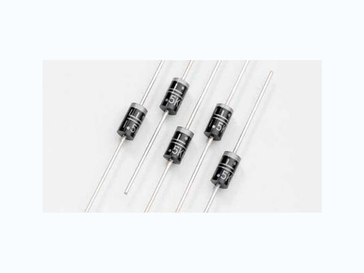
1.5KE_09 LITTELFUSE
Document overview
- Manufacturer or author: Provided By digicamel.com
- PDF pages: 5
Technical content
Features
The 1 .5KE Series is designed specifically to protect sensitive electronic equipment from voltage transients induced by lightning and other transient voltage events.
Description
Parameter Symbol Value Unit Peak Pulse Power Dissipation by 10x1000μs test waveform (Fig.1) (Note 1) PPPM 1500 W Steady State Power Dissipation on inifinite heat sink at TL=75ºC (Fig. 5) PD 6.5 W Peak Forward Surge Current, 8.3ms Single Half Sine Wave Unidirectional only (Note 2) I FSM 200 A Maximum Instantaneous Forward Voltage at 100A for Unidirectional only (Note 3) V F 3.5/5.0 V Operating Junction and Storage Temperature Range TJ, TSTG -55 to 175 °C Typical Thermal Resistance Junction to Lead RuJL 15 °C/W Typical Thermal Resistance Junction to Ambient RuJA 75 °C/W Notes: 1 . Non-repetitive current pulse , per Fig. 3 and derated above TA = 25OC per Fig. 2. 2. Measured on 8.3ms single half sine wave or equivalent square wave, duty cycle=4 per minute maximum. 3. VF<3.5V for devices of VBR _< 200V and VF<5.0V for devices of VBR _> 201V . Maximum Ratings and Thermal Characteristics (TA=25OC unless otherwise noted) Agency Approvals t)BMPHFO'SFF t3P)4DPNQMJBOU t5ZQJDBMNBYJNVN temperature coefficient ΔVBR = 0.1% x VBR@25°C x ΔT t(MBTTQBTTJWBUFEDIJQ junction in DO-201 Package t8QFBLQVMTF capability at 10×1000μs waveform, repetition rate (duty cycles):0.01% t'BTUSFTQPOTFUJNF typically less than 1 .0ps from 0 Volts to BV min t&YDFMMFOUDMBNQJOH capability t-PXJODSFNFOUBMTVSHF resistance t5ZQJDBM* R less than 1μA above 13V t)JHIUFNQFSBUVSF soldering guaranteed: 260°C/40 seconds / 0.375”,(9.5mm) lead length, 5 lbs., (2.3kg) tension t1MBTUJDQBDLBHFIBT Underwriters Laboratory Flammability classification 94V-O t.BUUF5JO-FBEoGSFFQMBUFE RoHS
T ransient Voltage Suppression Diodes Revision: January 09, 2009 ©2009 Littelfuse, Inc. Specifications are subject to change without notice. Axial Leaded – 1500W > 1.5KE series 1.5KE Series
Electrical Characteristics
(Uni) Part Number (Bi) Reverse Stand off Voltage VR (Volts) Breakdown Voltage VBR (Volts) @ IT Test Current IT (mA) Maximum Clamping Voltage VC @ Ipp (Volts) Maximum Peak Pulse Current Ipp (A) Maximum Reverse Leakage IR @ VR (μA) Agency Approval MIN MAX For bidirectional type having VR of 10 volts and less, the IR limit is double. For parts without A, the VBR is +10% and VC is 5% higher than with A parts.
T ransient Voltage Suppression Diodes Revision: January 09, 2009 ©2009 Littelfuse, Inc. Specifications are subject to change without notice. Axial Leaded – 1500W > 1.5KE series 1.5KE Series Physical Specifications Weight 0.045oz., 1 .2g Case JEDEC DO-201 molded plastic body over passivated junction. Polarity Color band denotes the cathode except Bipolar. T erminal Matte Tin axial leads, solderable per JESD22-B102D. Dimensions Dimensions Inches Millimeters Min Max Min Max A 1 .000 - 25.40 - B 0.285 0.375 7 .20 9.50 C 0.038 0.042 0.96 1 .07 D 0.190 0.210 4.80 5.30 D A A C B DO-201 Environmental Specifications T emperature Cycle JESD22-A104 Pressure Cooker JESD 22-A102 High T emp. Storage JESD22-A103 HTRB JESD22-A108 Thermal Shock JESD22-A106 Soldering Parameters Temperature (T Time (t) Ts(min) Ts(max) TL TP ts Preheat tL tp Ramp-up Critical Zone TL to TP Ramp-down t 25˚C to Peak 25˚C Reflow Condition -FBEoGSFFBTTFNCMZ Pre Heat - Temperature Min (Ts(min)) 150°C - Temperature Max (Ts(max)) 200°C - Time (min to max) (ts) oTFDT Average ramp up rate (Liquidus Temp (TL) to peak 3°C/second max TS(max) to TL - Ramp-up Rate 3°C/second max Reflow - Temperature (TL) (Liquidus) 217°C - Time (min to max) (ts) oTFDPOET Peak Temperature (TP) 260+0/-5 °C Time within 5°C of actual peak Temperature (tp) oTFDPOET Ramp-down Rate 6°C/second max Time 25°C to peak Temperature (TP) 8 minutes Max. Do not exceed 280°C Flow/Wave Soldering (Solder Dipping) Peak T emperature : 265OC Dipping Time : 10 seconds Soldering : 1 time
©2009 Littelfuse, Inc. Specifications are subject to change without notice. T ransient Voltage Suppression Diodes Revision: January 09, 2009 Axial Leaded – 1500W > 1.5KE series 1.5KE Series 1.5KE Series Part Numbering System Packaging Part Number Component Package Quantity Packaging Option Packaging Specification 1 .5KExxxXX DO-201 1200 Tape & Reel EIA STD RS-296E 1 .5KExxxXX-B DO-201 500 BULK Littelfuse Concord Packing Spec. DM-0016 VOLTAGE CODE (Refer to the Electrical Characteristics table) TYPE CODE: A Uni-Directional (5% Voltage Tolerance) CA Bi-Directional OPTION CODE: BLANK Reel Tape -B Bulk Packaging SERIES CODE 1.5KE xxxXX X Part Marking System F 1.5KEXXX Product Type Littelfuse Logo Cathode Band