
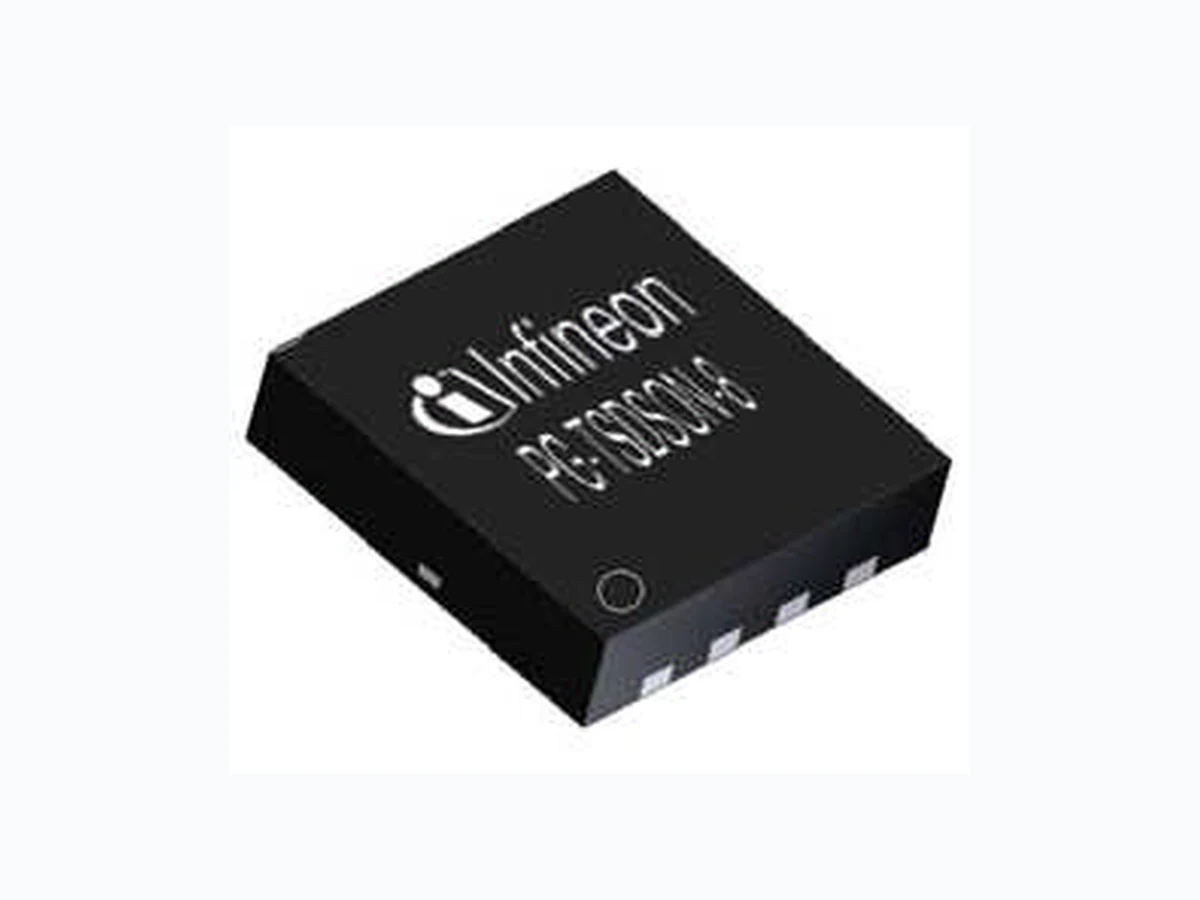
BSZ0909NS INFINEON
Document overview
- Manufacturer or author: Provided By digicamel.com
- PDF pages: 11
Technical content
Industrial & Multimarket Data Sheet 3.1, 2010-11-01 Final OptiMOS™ BSZ0909NS n-Channel Power MOSFET
OptiMOS™ Power-MOSFET BSZ0909NS Final Data Sheet 1 3.1, 2010-11-01 8 D 7 D 6 D 5 D S 1 S 2 S 3 G 4
1 Description
OptiMOS™30V products are class leading power MOSFETs for highest power density and energy efficient solutions. Ultra low gate- and output charges together with lowest on state resistance in small footprint packages make OptiMOS™ 30V the best choice forthe demanding requirements of voltage regulator solutions in Servers, Datacom and Telecom applications. Super fast switching Control FETs together with low EMI Sync FETs provide solutions that are easy to design in. OptiMOS™ products are available in high performancepackages to tackle your most challenging applications giving full flexibility in optimizing space- efficiency and cost. OptiMOS ™ products are designed to meet and exceed the energy efficiency and power density requirements of the sharpened next generation voltage regulation standards in computing applications
Features
- Optimized for high performance Buck converter
- 100% avalanche tested
- Very low on-resistance RDS(on) @ VGS=4.5 V
- Ultra low gate (Qg) and output charge (Qoss) for given RDS(on)
- Qualified according to JEDEC1) for target applications
- Superior thermal resistance
- Pb-free plating; RoHS compliant
- Halogen-free according to IEC61249-2-21
Applications
- On board power for server
- Power managment for high performance computing
- Synchronous rectification
- High power density point of load converters 1) J-STD20 and JESD22 Table 1 Key Performance Parameters Parameter Value Unit Related Links VDS 34 V IFX OptiMOS webpage RDS(on),max 12 m # IFX OptiMOS product brief ID 36 A IFX OptiMOS spice models QOSS 8.9 nC IFX Design tools Qg.typ 6.1 Type Package Marking BSZ0909NS PG-TSDSON-8 0909NS
OptiMOS™ Power-MOSFET BSZ0909NS Final Data Sheet 2 3.1, 2010-11-01
2 Maximum ratings
at Tj = 25 °C, unless otherwise specified.
3 Thermal characteristics
Parameter Symbol Values Unit Note / Test Condition Min. Typ. Max. Continuous drain current ID - - 36 A VGS=10 V, TC=25 °C
23 VGS=10 V, TC=100 °C
32 VGS=4.5 V, TC=25 °C 21 VGS=4.5 V, TC=100 °C 9 VGS=4.5 V, TA=25 °C, RthJA=60 K/W1)) 1) Device on 40 mm x 40 mm x 1.5 mm epoxy PCB FR4 with 6 cm2 (one layer, 70 µm thick) copper area for drain connection. PCB is vertical in still air. Pulsed drain current2) 2) See figure 3 for more detailed information ID,pulse - - 144 TC=25 °C Avalanche current, single pulse3) 3) See figure 13 for more detailed information IAS - - 20 Avalanche energy, single pulse EAS - - 9 mJ ID=20 A,RGS=25 # Gate source voltage VGS -20 - 20 V Power dissipation Ptot - - 25 W TC=25 °C
2.1 TA=25 °C, RthJA=60 K/W1))
Operating and storage temperature Tj,Tstg -55 - 150 °C IEC climatic category; DIN IEC 68-1 55 150 56 Ncm Table 3 Thermal characteristics Parameter Symbol Values Unit Note / Test ConditionMin. Typ. Max. Thermal resistance, junction - case RthJC - - 5.1 °K/W Device on PCB RthJA - - 60 6 cm 2 cooling area1) 1) Device on 40 mm x 40 mm x 1.5 mm epoxy PCB FR4 with 6 cm2 (one layer, 70 µm thick) copper area for drain connection. PCB is vertical in still air
OptiMOS™ Power-MOSFET BSZ0909NS
Electrical characteristics
Final Data Sheet 3 3.1, 2010-11-01
4 Electrical characteristics
Electrical characteristics, at Tj=25 °C, unless otherwise specified. Table 4 Static characteristics Parameter Symbol Values Unit Note / Test Condition Min. Typ. Max. Drain-source breakdown voltage V(BR)DSS 34 - - V VGS=0 V, ID=1.0 mA Gate threshold voltage VGS(th) 1 - 2 VDS=VGS, ID=250 µA Zero gate voltage drain current IDSS - 0.1 1 µA VDS=34 V, VGS=0 V, Tj=25 °C - 10 100 VDS=34 V, VGS=0 V, Tj=125 °C Gate-source leakage current IGSS - 10 100 nA VGS=16 V, VDS=0 V Drain-source on-state resistance RDS(on) - 12 15 m # VGS=4.5 V, ID=12 A - 10 12 VGS=10 V, ID=20 A Gate resistance RG - 3 - # Transconductance gfs 24 47 S | VDS|>2|ID|RDS(on)max, ID=30 A Table 5 Dynamic characteristics Parameter Symbol Values Unit Note / Test ConditionMin. Typ. Max. Input capacitance Ciss - 975 1310 pF VGS=0 V, VDS=15 V, f=1 MHzOutput capacitance Coss - 340 450 Reverse transfer capacitance Crss - 21 - Turn-on delay time td(on) - 4.5 - ns VDD=15 V, VGS=10 V, ID=30 A, RG= 1.6 #Rise time tr - 2.2 - Turn-off delay time td(off) - 16 - Fall time tf - 2 -
OptiMOS™ Power-MOSFET BSZ0909NS Final Data Sheet 4 3.1, 2010-11-01 Table 6 Gate charge characteristics 1) 1) See figure 16 for gate charge parameter definition Parameter Symbol Values Unit Note / Test ConditionMin. Typ. Max. Gate to source charge Qgs - 3.3 - nC VDD=15 V, ID=30 A, VGS=0 to 4.5 V Gate charge at threshold Qg(th) - 1.5 - Gate to drain charge Qgd - 1.6 - Switching charge Qsw - 3.2 - Gate charge total Qg - 6.1 8.1 Gate plateau voltage Vplateau - 3.4 - V Gate charge total Qg - 13 17 nC VDD=15 V, ID=30 A, VGS=0 to 10V Gate charge total, sync. FET Qg(sync) 5.3 VDS=0.1 V, VGS=0 to 4.5 V Output charge Qoss 8.9 VDD=15 V, VGS=0 V Table 7 Reverse diode characteristics Parameter Symbol Values Unit Note / Test ConditionMin. Typ. Max. Diode continuous forward current Is 23 A TC=25 °C Diode pulse current IS,pulse 148 Diode forward voltage VSD - 0.9 - V VGS=0 V, IF=20 A, Tj=25 °C Reverse recovery charge Qrr - - 10 nC VR=15 V, IF=Is, diF/dt=400 A/µs
OptiMOS™ Power-MOSFET BSZ0909NS Electrical characteristics diagrams Final Data Sheet 5 3.1, 2010-11-01
5 Electrical characteristics diagrams
1 Power dissipation 2 Drain current
Ptot = f(TC) ID=f(TC); parameter:VGS Table 9 3 Safe operating area TC=25 °C 4 Max. transient thermal impedance ID=f(VDS); Tj=25 °C; D=0; parameter: Tp Z(thJC)=f(tp); parameter: D=tp/T
OptiMOS™ Power-MOSFET BSZ0909NS Electrical characteristics diagrams Final Data Sheet 6 3.1, 2010-11-01 Table 10 5 Typ. output characteristics TC=25 °C 6 Typ. drain-source on-state resistance ID=f(VDS); Tj=25 °C; parameter: VGS RDS(on)=f(ID); Tj=25 °C; parameter: VGS Table 11 7 Typ. transfer characteristics 8 Typ. forward transconductance ID=f(VGS); |VDS|>2|ID|RDS(on)max gfs=f(ID); Tj=25 °C
OptiMOS™ Power-MOSFET BSZ0909NS Electrical characteristics diagrams Final Data Sheet 7 3.1, 2010-11-01 Table 12 9 Drain-source on-state resistance 10 Typ. gate threshold voltage RDS(on)=f(Tj); ID=20 A; VGS=10 V VGS(th)=f(Tj); VGS=VDS; ID=250 µA Table 13 11 Typ. capacitances 12 Forward characteristics of reverse diode C=f(VDS); VGS=0 V; f=1 MHz IF=f(VSD); parameter: Tj
OptiMOS™ Power-MOSFET BSZ0909NS Electrical characteristics diagrams Final Data Sheet 8 3.1, 2010-11-01 Table 14 13 Avalanche characteristics 14 Typ. gate charge IAS=f(tAV); RGS=25 parameter: Tj(start) VGS=f(Qgate); ID=30 A pulsed; parameter: VDD Table 15
15 Drain-source breakdown voltage 16 Gate charge waveforms
VBR(DSS)=f(Tj); ID=1 mA
OptiMOS™ Power-MOSFET BSZ0909NS Package outlines Final Data Sheet 9 3.1, 2010-11-01
6 Package outlines
Figure 1 Outlines PG-TSDSON-8, dimensions in mm/inches
OptiMOS™ Power-MOSFET BSZ0909NS
Revision History
Final Data Sheet 10 3.1, 2010-11-01
7 Revision History
We Listen to Your Comments Any information within this document that you feel is wrong, unclear or missing at all? Your feedback will help us to continuously improve the quality of this document. Please send your proposal (including a reference to this document) to: erratum@infineon.com Edition 2010-11-01 Published by Infineon Technologies AG
81726 Munich, Germany
© 2010 Infineon Technologies AG All Rights Reserved. Legal Disclaimer The information given in this document shall in no event be regarded as a guarantee of conditions or characteristics. With respect to any examples or hints given herein, any typical values stated herein and/or any information regarding the application of the device, Infineon Technologies hereby disclaims any and all warranties and liabilities of any kind, including without limitation, warranties of non-infringement of intellectual property rights of any third party. Information For further information on technology, delivery terms and conditions and prices, please contact the nearest Infineon Technologies Office (www.infineon.com). Warnings Due to technical requirements, components may contain dangerous substances. For information on the types in question, please contact the nearest Infineon Technologies Office. Infineon Technologies components may be used in life-support devices or systems only with the express written approval of Infineon Technologies, if a failure of such components can reasonably be expected to cause the failure of that life-support device or system or to affect the safety or effectiveness of that device or system. Life support devices or systems are intended to be implanted in the human body or to support and/or maintain and sustain and/or protect human life. If they fail, it is reasonable to assume that the health of the user or other persons may be endangered. Revision History: 2010-11-01, 3.1 Previous Revision: Revision Subjects (major changes since last revision)