

 Download PDF
0805CDMA AVX
Document overview
- Manufacturer or author: Provided By digicamel.com
- PDF pages: 2
Technical content
Multilayer Organic (MLOTM)
0805 CDMA Diplexer
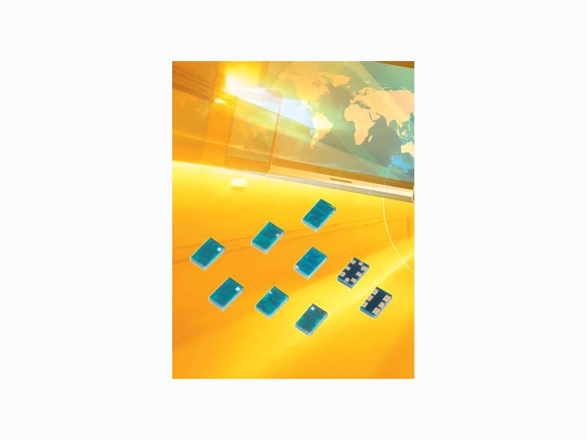
The 0805 diplexer is a best in class low profile multilayer organic passive device that is based on AVX’s patented multilayer organic high density interconnect technology. The MLO TM diplexer uses high dielectric constant and low loss materials to realize high Q passive printed passive elements such as inductors and capacitors in a multilayer stack up. The MLO TM diplexers can support multiple wireless standards such as WCDMA, CDMA, WLAN, and GSM and are less than 0.6mm in thickness. These components are ideally suited for band switching for dual band systems. All diplexers are expansion matched to FR4 thereby resulting in improved reliability over standard Si and ceramic devices.
APPLICATIONS
Multiband applications including WCDMA, WLAN, WiMax, GPS, and cellular bands LAND GRID ARRAY ADVANTAGES
- Low Insertion Loss
- Excellent Solderability
- Low Parasitics
- Low Profile QUALITY INSPECTION Finished parts are 100% tested for electrical parameters and visual characteristics. OPERATING TEMPERATURE -40ºC to +85ºC TERMINATION Finishes available in Ni/Sn, Immersion Sn, Immersion Au and OSP coatings which are compatible with automatic soldering technologies which include reflow, wave soldering, vapor phase and manual. PART NUMBER: DP05A19207TR Specification @ 25ºC Size [mm(inches)] 2.12 x 1.28 (0.083 x 0.050) Height [mm(inches)] 0.55 (0.021) Volume (mm^3) 1.5 Frequency Range (F1) (MHz) 859±35 Frequency Range (F2) (MHz) 1920±70 Insertion Loss (F1, at Fc) (dB) -0.4 Insertion Loss (F2, at Fc) (dB) -0.6 Attenuation (F1) at (F2) (dB) -23 Attenuation (F2) at (F1) (dB) -23 VSWR (Input @ F1) 1.4 VSWR (Input @ F2) 1.3 VSWR (Lowband @ F1) 1.4 VSWR (Highband @ F2) 1.4 A Design 1920 Frequency (MHz) Finish 7 = Au T = NiSn TR Packaging Tape & Reel TR = 3 Kpcs TR/500 = 500 pcs HOW TO ORDER DP Type Size Bottom View Side View 0.20±0.10 (0.008±0.004) 0.20±0.10 (0.008±0.004) 2.12±0.20 (0.083±0.008) 0.44±0.10 (0.017±0.004) 0.55±0.10 (0.022±0.004) 0.64±0.05 (0.025±0.002) 0.04±0.04 (0.002±0.002) 0.25±0.10 (0.010±0.004) 1.28±0.20 (0.050±0.008) 0.95±0.05 (0.037±0.002) Unit: mm (inches) COMPONENT DIMENSIONS AND FUNCTIONS Terminal No. Terminal Name
1 High Frequency Port
3 Low Frequency Port
5 Common Port
4.5W Maximum ORIENTATION IN TAPE Top View
Multilayer Organic (MLOTM) -10 -15 -20 -25 -30 -35 dB(S(1,1) dB(S(3,1) freq, GHz dB(S(2,3)) -10 -15 -20 -25 -30 -35 -40 dB(S(1,1) dB(S(2,1) freq, GHz -12 -14 -16 -18 -20 -22 -24 -26 -28 -30 -32 freq, GHz Low Band Return Loss High Band Return Loss Isolation Note: Measurements were taken using an Anritsu 4 port VNA; Diplexer was mounted on a custom evaluation board. To reduce systematic errors from the VNA, the coaxial measurement cables, and evaluation board, a Short-Open-Load-Thru (SOLT) calibration was performed, using a custom fabricated ca libration substrate. This is the most common coaxial calibration methods. 128