
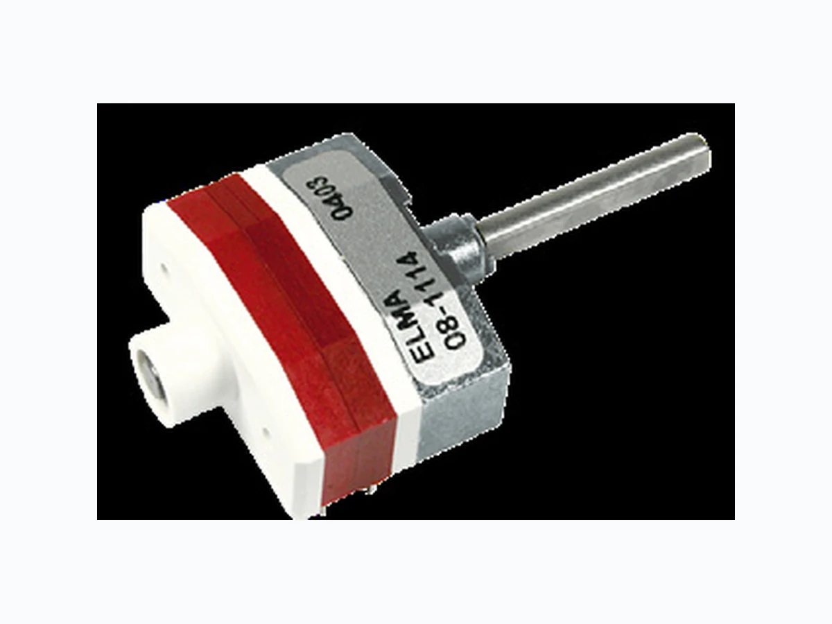
08-1103 ELMA
Document overview
- Manufacturer or author: Provided By digicamel.com
- PDF pages: 8
Technical content
www.elma.com06|20 1|8 11/65/EU) SELECTOR SWITCH DATASHEET Product description MAIN FEATURES HORIZONTAL, MULTI WAFER, PCB MOUNTING, UP TO 12 POSITIONS › For PCB mounting › 25'000 switching cycles with up to 9 Ncm switching torque › Gold plated contacts 3 micron › Robust metal housing with metal shaft › Operating temperature range: -40 to +85 °C › Various options and customizations PRODUCT VARIETY ■ From 1 x 12 to 4 x 3 poles x positions per wafer ■ Up to 8 wafers ■ Shorting or non-shorting ■ Switching torque: 3, 6 or 9 Ncm ■ Configurable end stops POSSIBLE CUSTOMIZATIONS ■ Shaft dimension and shape ■ Switching torque ■ Hollow shaft, inner shaft ■ Others TYPICAL APPLICATIONS ■ Industrial controls ■ Avionics systems ■ Test and measurement devices ■ Medical and audio equipment
www.elma.com06|20 2|8 SELECTOR SWITCH DATASHEET Dimensions and pin assignment SWITCH DESIGN AND DRILLING DIAGRAM SWITCH WITH 2 WAFERS Ax = Common contact water of x Bx = Switching contact wafer of x * L1 1 wafer 28.25 mm ±0.3 mm 2 wafers 38.32 mm ±0.3 mm 3 wafers 48.40 mm ±0.3 mm 4 wafers 58.45 mm ±0.3 mm per additional wafer +10.08 mm ** All further steps are in 5.08 mm pitch Dimensions in mm Tolerances according to DIN ISO 2768-1 (m), unless otherwise specified
www.elma.com06|20 3|8 A = 1 B = 2 C = 4 D = 8 SELECTOR SWITCH DATASHEET For 12 positions the coding will be made according to the layout on the left (on the printed circuit). If the switch is com- posed of component parts, the housings A (3 x 4) and B (1 x 12) have to be ordered. Limiting to 10 positions (BCD) is done with a stop screw M1.2 x 2.5. Bottom view: BCD Coding 8 4 2 1 On Off Dimensions and pin assignment SWITCH DESIGN AND DRILLING DIAGRAM SWITCH WITH BCD CODING
12 Position BCD coding
www.elma.com06|20 4|8 SELECTOR SWITCH DATASHEET
Ordering information
00 Standard
000 30.8 mm xxx1 Customized (shaft length rounded to next 0.5 mm, e.g. 10.3 mm = 10.5 mm or 10 mm)
1 Customized shaft length (AL)
AL measured from mounting face (see picture below) Max. shaft length (AL): 30.8 mm SHAFT LENGTH (AL) See standard types NUMBER OF WAFERS See standard types NUMBER OF POLES See standard types FACTORY SET CHARACTER
3 Shorting
4 Non-shorting
- 6 Ncm (standard) M 3 Ncm N 9 Ncm SWITCHING TORQUE
www.elma.com06|20 5|8 121110 987654321 121110 987654321 121110 987654321 121110 987654321 111cb a ba 121110 987654321 1111dc ba 121110 987654321 121110 987654321 121110 987654321 121110 987654321 111cb a ba 121110 987654321 1111dc ba 121110 987654321 121110 987654321 121110 987654321 121110 987654321 111cb a ba 121110 987654321 1111dc ba 121110 987654321 121110 987654321 121110 987654321 121110 987654321 111cb a ba 121110 987654321 1111dc ba 121110 987654321 121110 987654321 121110 987654321 121110 987654321 111cb a ba 121110 987654321 1111dc ba 121110 987654321 121110 987654321 121110 987654321 121110 987654321 111cb a ba 121110 987654321 1111dc ba 121110 987654321 121110 987654321 121110 987654321 121110 987654321 111cb a ba 121110 987654321 1111dc ba 121110 987654321 121110 987654321 121110 987654321 121110 987654321 111cb a ba 121110 987654321 1111dc ba 121110 987654321 121110 987654321 121110 987654321 121110 987654321 111cb a ba 121110 987654321 1111dc ba 121110 987654321 121110 987654321 121110 987654321 121110 987654321 111cb a ba 121110 987654321 1111dc ba SELECTOR SWITCH DATASHEET CONTACT ARRANGEMENT NUMBER OF WAFERS FUNCTION PART NUMBER COMMON WAFER PART CONTACT SWITCHING WAFER PART CONTACT (POLES X POSITIONS) SHORTING NON-SHORTING 1 1 x 12 | endless rotating 08 -1103 08-1104 2 2 x 12 | endless rotating 08-2103 08-2104 3 3 x 12 | endless rotating 08-3103 08-3104 4 4 x 12 | endless rotating 08-4103 08-4104 1 1 x 12 08 -1113 08 -1114 2 2 x 12 08 -2113 08 -2114 3 3 x 12 08 - 3113 08 - 3114 4 4 x 12 08 - 4113 08 - 4114 1 2 x 6 08-1263 08-1264 2 4 x 6 08-2263 08-2264 3 6 x 6 08-3263 08-3264 4 8 x 6 08-4263 08-4264 1 3 x 4 08-1343 08-1344 2 6 x 4 08-2343 08-2344 3 9 x 4 08-3343 08-3344 4 12 x 4 08-4343 08-4344 1 4 x 3 08-1433 08-1434 2 8 x 3 08-2433 08-2434 3 12 x 3 08-3433 08-3434 4 16 x 3 08-4433 08-4434 PACKAGING Foam polystyrene box: Quantity depends on switch configuration
1 For other types | options see ordering code
*The common connection is to be connected on printed circuit boards ACCESSORIES AND SPARE PARTS Fixing screw M2 x 6: Part number 4224-01 (10 pieces / bag), steel Stop screw M1.2: Part number 4224-1 1 (10 pieces / bag), steel Stop screw M1.2: Part number 4224-10 (100 pieces / bag), steel Stop screw: Configurable stop screws can be attached at any position between two and the maximum. Stop screws must be ordered separately. PREFERENCE TYPES SELECTION CHART 1
www.elma.com06|20 6|8 Mechanism Shaft Housing View of wafer from front side Pin 1Pin 12 14.8 L Shaft Mechanism Shaft Housing View of wafer from front side Pin 1Pin 12 14.8 L Shaft Mechanism Shaft Housing View of wafer from front side Pin 1Pin 12 14.8 L Shaft SELECTOR SWITCH DATASHEET FUNCTION PART NUMBER (POLES X POSITIONS) SHORTING NON-SHORTING 1 x 12 4217-10 4218-10 2 x 6 4217-11 4218 -11 3 x 4 4217-13 4218-13 4 x 3 4217-12 4218-12 Wafer Shaft Mechanism Wafer View from front side Shaft NUMBER OF POLES POSITIONS SWITCHING TORQUE PART NUMBER ≤ 6 12 6 Ncm 4214-10 > 6 12 9 Ncm 4214-12 Switch mechanism Shaft including assembly material LENGTH L NUMBER OF HOUSINGS PART NUMBER 75 mm 3 4211- 05 100 mm 5 4211-10 125 mm 7 4211-15 150 mm 9 4211-20 ACCESSORIES AND SPARE PARTS Available in kit form: Mechanism, wafer and shaft are supplied separately. This offers more possibilities to place the switch onto the PC board.
www.elma.com06|20 7|8 IA ±0.2 SELECTOR SWITCH DATASHEET Customized solutions HOLLOW SHAFT SYSTEM HOLLOW SHAFT Available for switches up to 4 wafers. Inner shaft (Ø 2 mm) must be ordered separately. Must be ordered separately for switches with hollow shaft. Consisting of a hollow outer and inner shaft. The inner shaft driving a max. of 3 wafers with 4 wipers each. Please indicate type of each switch. Top view: INNER SHAFT SWITCH WITH CONCENTRIC SHAFTS
www.elma.com 8|806|20 ©Copyright 2018 by Elma Electronic AG, CH-8620 Wetzikon. Subject to technical modifications, all data supplied without liability. SELECTOR SWITCH DATASHEET Please contact our sales team for more details. China: +86 21 5866 5908 France: +33 388 56 72 50 Germany: +49 7231 97 34 0 Israel: +972 3 930 50 25 Singapore: +65 6479 8552 Switzerland: +41 44 933 41 1 1 United Kingdom: +44 1234 838 822 United States: +1 510 656 3400 MECHANICAL DATA Detent angle | positions: 30° detent angle | 12 positions Rotary limitation | end stop: Configurable Switching torque: 3, 6 or 9 Ncm (±25 % in new condition) Rotational life: > 25'000 cycles (tested at room temperature) ELECTRICAL DATA Electrical connection: Pins 0.4 x 0.75 mm Switching voltage: < 42 VDC (resistive load) Switching current: < 1'500 mA (resistive load) Contact resistance: < 20 mΩ (in new condition) Switching capacity: < 1 pF (between the contacts) Switching function: 1 x 12 to 4 x 3 poles x positions per wafer, max. 8 wafers Switching mode: Shorting or non-shorting Dielectric strength: 500 VDC during 60 s (pin-to-pin, pin-to-housing) Insulation resistance: > 1 GΩ at 500 VDC (pin-to-pin, pin-to-housing, in new condition) MATERIALS Shaft: Stainless steel 1.4305 Bushing | housing: Zinc die casting (zinc plated and passivated) Contact surface: Cu alloy (Au plated) Insulation material: Wafer: PA6/6T Rotor: Polyacetal (POM) Soldering leads: Cu alloy (tin plated) ENVIRONMENTAL DATA Operating temperature: -40 to +85 °C (IEC 60068-2-14) Storage temperature: -40 to +85 °C (IEC 60068-2-14) IP sealing against front panel: IP60 only shaft sealing Vibration: 10 GRMS at 10 to 2'000 Hz Flammability: UL94-HB SOLDERING CONDITIONS Hand soldering: < 340 °C during 2 s Wave soldering: < 280 °C during 5 s Specifications