

 Download PDF
3AG_V01 BEL
Document overview
- PDF pages: 4
Technical content
Page 1

Fast Blow Fuse Series
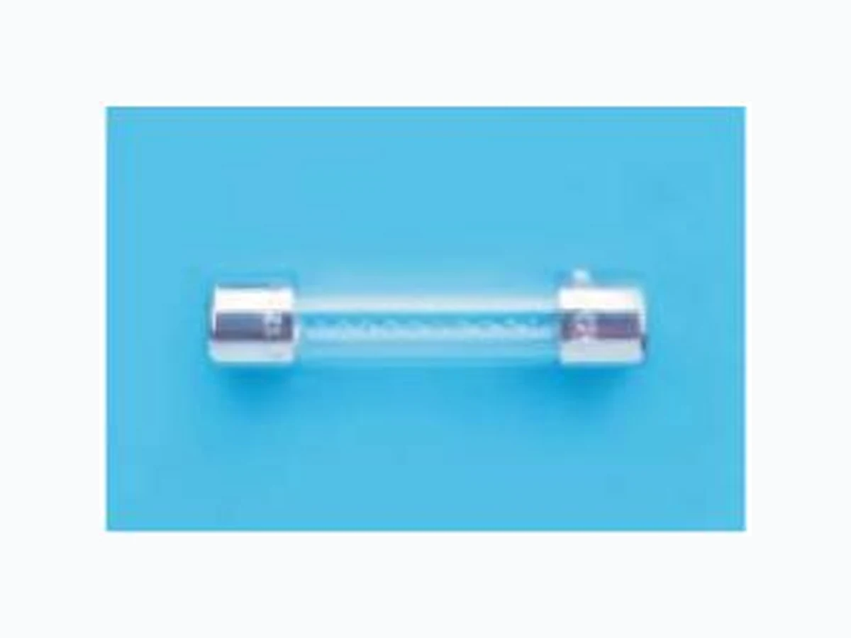
3AG Series, 6x32mm Glass Tube Fast Blow Fuse RoHS Compliant
Description
6x32mm Fast Blow, glass tube body cartridge fuse designed, approved and complied with UL and CSA standard 248-14.
Features
- Meet UL and CSA standard 248-14 - Wide operating temperature range - Bulk packing available - Full compliance with EU Directive 2011/65/EU and amending directive 2015/863 - Halogen Free - Lead Free
Applications
Provide individual protection for components or internal circuits. - Power supplies - Battery charger - Monitor LEAD FREE =
- Adapter HALOGEN FREE =
Physical Specifications
| Materials | Body : Glass |
| Cap : Nickel Plated Brass Caps | |
| Leads : Matte Tin Plated Copper | |
| Marking | On Fuse : |
| “bel”, "3AG”, "Current Rating”, “Voltage Rating”, | |
| ”Appropriate Safety Logos”, ” ”( RoHS compliant) | |
| On Label : | |
| "bel", "3AG”, "Current Rating", "Voltage Rating", "Interrupting Rating", "Appropriate Safety Logos" and " ", " "(China RoHS compliant). |
Electrical Characteristics (UL/CSA STD.248-14) Safety Agency Approvals
| Safety Agency | Safety Agency Certificate | Ampere Rating/ Voltage Rating | Ampere Range / Volt @ I.R. ability* |
| E506667 | 500mA–10A/ 250V AC 12A-15A/ 125V AC | 500mA-10A/250V AC@200A 500mA-15A/125V AC@10,000A | |
| LR39772 | |||
| *I.R.= Interrupting Rating = Short Circuit Rating(Amps) | |||
| Testing Current | Blow Time | |
| Minimum | Maximum | |
| 100% | 4 hrs. | N/A |
| 135% | N/A | 1 hr. |
| 200% | N/A | 5 sec |

Specifications subject to change without notice
Page 2
2 / 4
Environmental Specifications
| Shock Resistance | MIL-STD-202G, Method 213B, Test Condition 1 (100 G's peak for 6 milliseconds; Sawtooth waveform) |
|---|---|
| Vibration Resistance | MIL-STD-202G, Method 201A (10-55 Hz, 0.06 inch, total excursion). |
| Salt Spray Resistance | MIL-STD-202G, Method 101E, Test Condition B (48 hrs). |
| Insulation Resistance | MIL-STD-202G, Method 302, Test Condition A (After Opening) 10,000 ohms minimum. |
| Solderability | MIL-STD-202G, Method 208H |
| Resistance to solder Heat | MIL-STD-202G, Method 210F, Test Condition B (260+/-5℃,10+/-1 sec) |
| Thermal Shock | MIL-STD-202G, Method 107G, Test Condition B (-65℃ to +125℃). |
| Operating Temperature | -55℃ to +125℃ |
| Terminal Strength | IEC-68-2-21 |
Electrical Specifications
| Catalog Number | Ampere Rating | Typical Cold Resistance (ohms) | Volt-drop @100%In (Volt) max. | Voltage and Interrupting Ratings | Melting I²T <10 mSec (A² Sec) | Melting I²T @10 In (A² Sec) | Maximum Power Dissipation (W) | Agency Approvals | |
|---|---|---|---|---|---|---|---|---|---|
| 3AG 500-R | 500mA | 1.19 | 3.17 | See Table of Safety Approvals on Page 1 for Voltage and associated Interrupting Ratings | 0.14 | 0.11 | 1.88 | Y | Y |
| 3AG 750-R | 750mA | 0.66 | 2.54 | 0.19 | 0.17 | 2.15 | Y | Y | |
| 3AG 1-R | 1A | 0.155 | 0.28 | 1.4 | 1.4 | 0.37 | Y | Y | |
| 3AG 1.25-R | 1.25A | 0.114 | 0.27 | 2.4 | 2.5 | 0.44 | Y | Y | |
| 3AG 1.6-R | 1.6A | 0.085 | 0.27 | 4.2 | 4.4 | 0.51 | Y | Y | |
| 3AG 2-R | 2A | 0.057 | 0.22 | 7.2 | 7.6 | 0.59 | Y | Y | |
| 3AG 2.5-R | 2.5A | 0.043 | 0.21 | 12 | 13 | 0.70 | Y | Y | |
| 3AG 3-R | 3A | 0.033 | 0.17 | 21 | 23 | 0.83 | Y | Y | |
| 3AG 3.5-R | 3.5A | 0.027 | 0.18 | 28 | 31 | 0.91 | Y | Y | |
| 3AG 4-R | 4A | 0.024 | 0.17 | 36 | 40 | 1.00 | Y | Y | |
| 3AG 5-R | 5A | 0.018 | 0.16 | 63 | 70 | 1.20 | Y | Y | |
| 3AG 6-R | 6A | 0.014 | 0.15 | 107 | 123 | 1.40 | Y | Y | |
| 3AG 7-R | 7A | 0.012 | 0.16 | 141 | 162 | 1.60 | Y | Y | |
| 3AG 8-R | 8A | 0.010 | 0.15 | 184 | 214 | 1.70 | Y | Y | |
| 3AG 10-R | 10A | 0.008 | 0.13 | 316 | 372 | 2.00 | Y | Y | |
| 3AG 12-R | 12A | 0.006 | 0.13 | 501 | 597 | 2.40 | Y | Y | |
| 3AG 15-R | 15A | 0.005 | 0.13 | 1400 | 1500 | 1.80 | Y | Y | |
Consult manufacturer for other ratings

Specifications subject to change without notice
Page 3
3 / 4
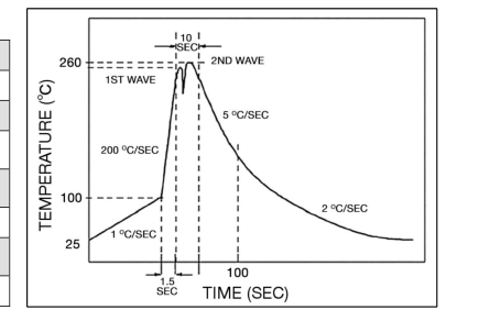
Temperature Derating Curve Average Time Current Curve
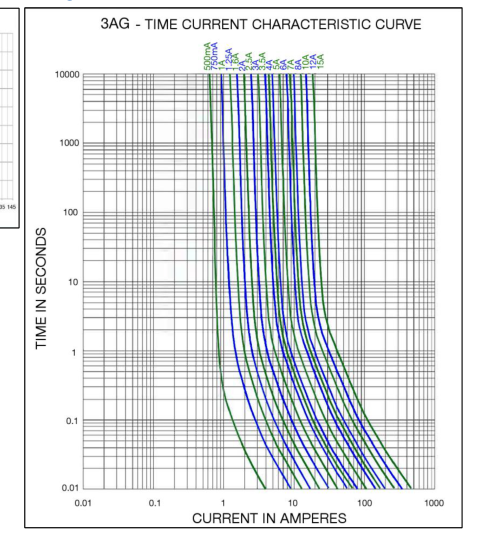
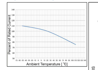
Soldering Parameters
| Lead-free Wave Soldering Profile | |
| Wave Soldering Parameter | |
| Average ramp-up rate | 200℃ / second |
| Heating rate during preheat | typical 1 - 2℃ / second Max 4℃ / second |
| Final preheat temperature | within 125℃ of soldering temperature |
| Peak temperature Tp | 260℃ |
| Time within +0℃ / -5℃ of actual peak temperature | 10 seconds |
| Ramp-down rate | 5℃ / second max. |

Specifications subject to change without notice
Page 4
4 / 4
Fuse FGNO Explanation
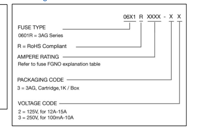
06X1 R [XXXX] -XX
0601R=3AG; [XXXX]=Ampere Rating; XX=See Ordering Information as below
| Fraction | Decimal | Milliamps | Bel FGNO[XXXX] |
| 1/2 | .500 | 500 | 0500 |
| 3/4 | .750 | 750 | 0750 |
| Fraction | Decimal | Amps | Bel FGNO[XXXX] |
| 1.0 | 1 | 1000 | |
| 1-1/4 | 1.25 | 1.25 | 1250 |
| 1.60 | 1.6 | 1600 | |
| 2.0 | 2 | 2000 | |
| 2-1/2 | 2.5 | 2.5 | 2500 |
| 3.0 | 3 | 3000 | |
| 3-1/2 | 3.5 | 3.5 | 3500 |
| 4.0 | 4 | 4000 | |
| 5.0 | 5 | 5000 | |
| 6.0 | 6 | 6000 | |
| 7.0 | 7 | 7000 | |
| 8.0 | 8 | 8000 | |
| 10 | 9100 | ||
| 12 | 9120 | ||
| 15 | 9150 |
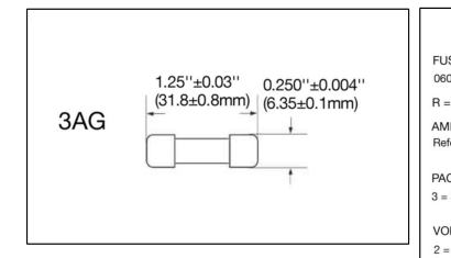
Mechanical Dimensions Ordering Information
Packaging
| Packaging Option | Packaging Specification | Quantity | Packaging Code | Inside Tape Spacing |
| Bulk | N/A | 1000 | 33 / 32 | N/A |

Specifications subject to change without notice