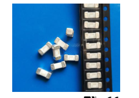
Slow Blow, 2410 SMD - Compatible with 260℃, IR Pb-free solder process - Wide range of current rating from 500mA to 15A - Wide operating temperature range, -55℃ to 125℃ - Tape & Reel for auto-insert SMD process - AEC-Q Compliant - RoHS compliant with exemption 7(a) Full compliance with EU Directive 2011/65/EU and amending directive 2015/863
Halogen Free, (MSL = 1) - Meets Bel automotive qualification\* \* - Largely based on internal AEC-Q test plan
Applications
Notebook -Storage system - LCD monitor -Telecom system - PC computer -Wireless basestation - Office electronic equipment -White goods - Industrial equipment -Game console - Medical equipment -Battery charging circuit protection - POE, POE+ - LCD / LED monitor - Power supply
MIL-STD-202G Method 213,Test condition A (50G’s peak for 11 milliseconds : Half-sine waveform )
Vibration Resistance
MIL-STD-202G, Method 201A (10-55 Hz, 0.06 inch, total excursion).
Salt Spray Resistance
MIL-STD-202G, Method 101E, Test Condition B (48 hrs.).
Insulation Resistance
MIL-STD-202G, Method 302, Test Condition A (After Opening) 10,000 ohms minimum.
Thermal Shock
MIL-STD-202G, Method 107G, Test Condition B (-65℃ to +125℃).
Operating Temperature
-55℃ to +125℃
Moisture Sensitivity Level
1 (According to IPC J-Std-020)
High temperature storage
MIL-STD-202 Method 108
Temperature cycling
JESD22 Method JA-104,Test Condition B
Biased humidity
MIL-STD-202 Method 103, 85C/85% RH with 10% operating power for 1000 hrs.
Operational life
MIL-STD-202 Method 108, Test Condition D
Resistance to solvents
MIL-STD-202 Method 215
Mechanical shock
MIL-STD-202 Method 213,Test Condition C
Vibration
MIL-STD-202G Method 204 Test condition D(10-2k HZ ,20G’s for 20minutes)
Resistance to soldering heat
MIL-STD-202 Method 210,Test condition B
Thermal shock
MIL-STD-202 Method 107
Solderability
J-STD-002 Test B
Board flex(SMD)
AEC-Q200-005
Terminal strength
AEC-Q200-006
Electrical characterization
3 Temperature Electrical
Electrical Specifications
Part Number
Ampere Rating
Typical Cold Resistance (ohms)
Nominal Volt-drop @100% In (Volt)
Voltage and Interrupting Ratings
Nominal melting I²T @10 In (A² Sec)
Nominal melting I²T <10ms (A² Sec)
Nominal Power Dissipation (W)
Agency Approvals
0680H0500-XX
500mA
1.1
1.5
See Table of Safety Approvals on Page 1 for Voltage and associated Interrupting Ratings
0.13
0.10
0.75
Y
0680H0630-XX
630mA
0.83
1.1
0.20
0.13
0.69
Y
0680H0750-XX
750mA
0.53
0.85
0.28
0.29
0.64
Y
0680H1000-XX
1A
0.33
0.65
0.79
0.80
0.65
Y
0680H1500-XX
1.5A
0.175
0.60
1.7
1.8
0.90
Y
0680H2000-XX
2A
0.095
0.40
3.6
3.9
0.80
Y
0680H2500-XX
2.5A
0.065
0.38
5.9
6.1
0.95
Y
0680H3000-XX
3A
0.051
0.34
8.3
8.7
1.0
Y
0680H3500-XX
3.5A
0.042
0.32
12
15
1.1
Y
0680H4000-XX
4A
0.032
0.31
15
18
1.2
Y
0680H5000-XX
5A
0.026
0.30
24
26
1.5
Y
0680H6300-XX
6.3A
0.023
0.28
32
34
1.8
Y
0680H7000-XX
7A
0.015
0.25
48
52
1.8
Y
0680H8000-XX
8A
0.012
0.23
59
65
1.8
Y
0680H9100-XX
10A
0.0096
0.23
98
102
2.3
Y
0680H9120-XX
12A
0.0077
0.22
141
146
2.6
Y
0680H9150-XX
15A
0.0066
0.20
207
213
3.0
Y
Consult manufacturer for other ratings XX - Packaging code (see “ordering information”)
NOTES 1: All tests were conducted with the fuses soldered to a printed circuit boards with a nominal thickness of 1.6 mm. The copper test circuit trace was a printed circuit with an overall length of 100 mm, copper thickness/width as described below. The printed circuit boards were mounted by screws to a test fixture having brass blocks for connection of the test leads. All samples were soldered to the test boards by the manufacturer.
Fuse rating
Test Board Trace Dimensions
500mA-5A
1 oz. copper, 5mm wide.
6A-15A
3 oz. copper, 10mm wide.
NOTES 2: Conventional (Ambient Pressure) Reflow Process is recommended for this device. The sale and use of product is subject to bel terms and condition of sale,unless otherwise agreed .User should independently evaluate the suitability of and test each product selected for their own application. product are not designed for ,and may not be used in,all applications. Caution: - Minimum fusing point: The 0680H Series fuse are NOT intended to be operated at currents between 100% and 200% of ampere rating. Prolonged operation at currents in this range may result in overheating of the fuse and/or desoldering of the fuse caps from the PCB pad.
Specifications subject to change without notice
Page 3
3 / 4
Temperature Derating Curve Average Time Current Curve
0680H - TIME CURRENT CHARACTERISTIC CURVE 500mA 630mA 750mA 1A 1.5A 2A 2.5A 3A 3.5A 4A 5A 6.3A 7A 8A 10A 12A 15A 10000 1000 100 SECONDS 10 IN TIME 1 0.1 0.01 0.01 0.1 1 10 100 1000 CURRENT IN AMPERES
Soldering Parameters
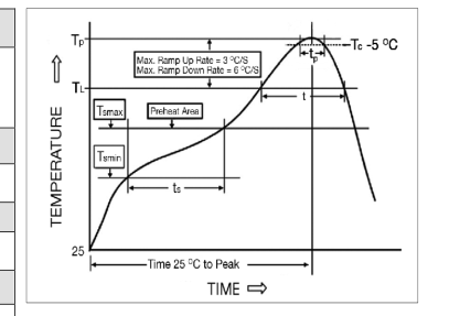
IR Reflow Profile (IPC/JEDEC J-STD-020D)
Preheat & Soak Temperature min (Tsmin) Temperature max (Tsmax) Time (Tsmin to Tsmax) (ts)
1 5 0 ℃ 2 0 0 ℃ 6 0 - 1 2 0 s e c onds
Average ramp-up rate (Tsmax to Tp)
3℃/second max.
Liquidous temperature (TL) Time at liquidous (tL)
2 1 7 ℃ 60-150 seconds
Peak temperature (Tp)
260℃ max
Time (tp) within 5℃ of the specified classification temperature (Tc)
30 seconds
Average ramp-down rate (Tp to Tsmax)
6℃/second max.
Time 25℃ to peak temperature
8 minutes max.
Specifications subject to change without notice
Page 4
4 / 4
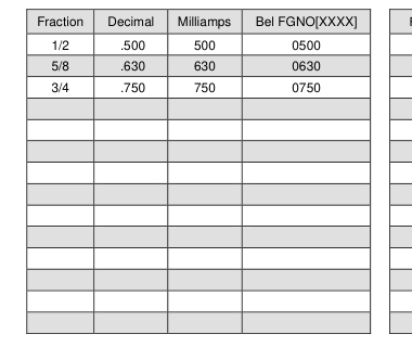
Fuse FGNO Explanation
0680 H [XXXX] -XX
0680H=0680H; [XXXX]=Ampere Rating; XX=See Ordering Information as below
Fraction
Decimal
Amps
Bel FGNO[XXXX]
1.0
1
1000
1-1/2
1.5
1.5
1500
2.0
2
2000
2-1/2
2.5
2.5
2500
3.0
3
3000
3-1/2
3.5
3.5
3500
4.0
4
4000
5.0
5
5000
6.3
6.3
6300
7.0
7
7000
8.0
8
8000
10
9100
12
9120
15
9150
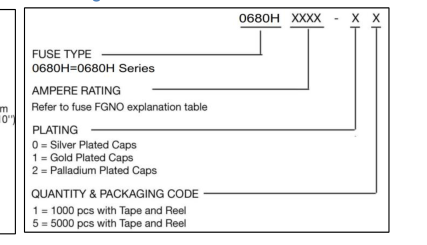
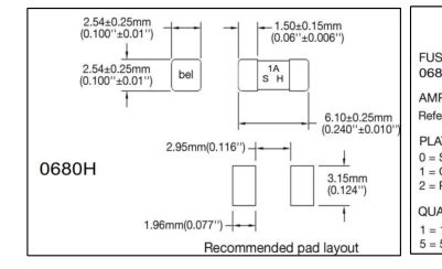
Mechanical Dimensions Ordering Information
Packaging
Packaging Tape & Reel
Packaging Specification
Quantity
Quantity & Packaging Code
12 mm wide tape with 13 inches Diameter reel
EIA Standard 481-E
5000
5
12 mm wide tape with 7 inches Diameter reel
EIA Standard 481-E
1000
1
Specifications subject to change without notice
Selected Specification
Bel Fuse Inc. 0680HFGNO-01 overview.
Overview
0680HFGNO-01 is listed in the IC category. Available datasheets include documents from Bel Fuse Inc.. DigiCamel provides a local PDF and searchable HTML technical text for online reference.


 Download PDF